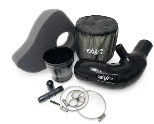
Can-Am X3 High Flow Intake (45mm & 47mm Throttle Body)

X3 High Flow Intake

Category
Intake
SKU
Stock Turbo 45mm (1772010001), Dynomite 47mm (1782010002), Desert Storm 76mm (1782010003)
Legacy SKU
203FC0076, 203FC0037, 203FC0039
Revision
Rev_031822

In the box

Parts and tools

X3 High Flow Intake

Included parts

  • 1EVP Air Filter with Pre-Filter
  • 1EVP Foam Insert
  • 1Silicone Intake Tube
  • 14”-3” Reducer
  • 1Hardware Kit

Required tools

  • 13mm Socket
  • 7mm Socket
  • T-30 Torx
  • Dremel or Cutting Tool
  • Silver Sharpie

Procedure

Installation Steps

  1. Step 1

    Remove the turbo access cover located on the firewall, between the seats.

  2. Step 2

    Remove or slide the drivers side seat forward.

  3. Step 3

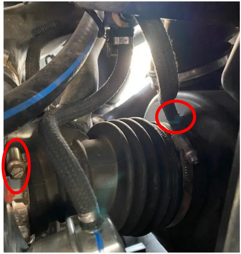
    Through the turbo access cover, loosen the worm drive clamp connecting the intake tube to the turbo and the worm drive clamp connecting the air box to the intake above. Remove the boost reference port hose coming from the boost solenoid and the crank case breather hose.
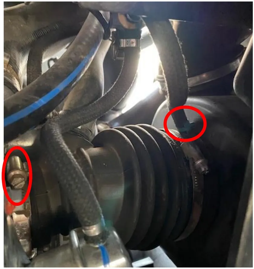
    Through the turbo access cover, loosen the worm drive clamp connecting the intake tube to the turbo and the worm drive clamp connecting the air box to the intake above. Remove the boost reference port hose coming from the boost solenoid and the crank case breather hose.
  4. Step 4

    Remove the (2) 13mm bolts behind the seat that hold the air box to the firewall.
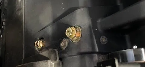
    Remove the (2) 13mm bolts behind the seat that hold the air box to the firewall.
  5. Step 5

    Remove the OEM air box and filter. It is easier to remove the sway bar nut and push the sway bar forward. Below is the air box removed.
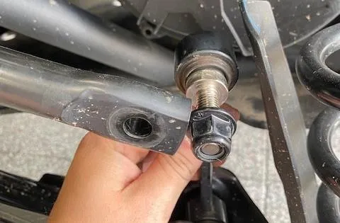
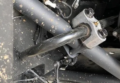
    Remove the OEM air box and filter. It is easier to remove the sway bar nut and push the sway bar forward. Below is the air box removed.
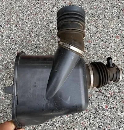
    Remove the OEM air box and filter. It is easier to remove the sway bar nut and push the sway bar forward. Below is the air box removed.
    Remove the OEM air box and filter. It is easier to remove the sway bar nut and push the sway bar forward. Below is the air box removed.
  6. Step 6

    Remove the cover over the coolant bottle and remove the white screen cover over the intake.

  7. Step 7

    If the rubber boot is still fixed in the air box shroud, you can pull it out. You do not need to remove the air box to do this.
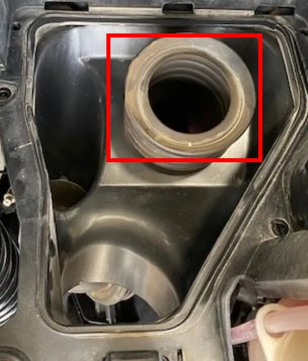
    If the rubber boot is still fixed in the air box shroud, you can pull it out. You do not need to remove the air box to do this.
  8. Step 8

    Build your silicone intake tube like shown below. 3/4-3/4” barb goes into the 3/4" hole with a pinch clamp for the crank case breather or boost recirculating valve. If you have a catch can, you will cap this plug with the 3/4" silicone cap. The 3/16” barb will go into the 3/16” port with a pinch clamp. This is for your boost reference port. Slide the silicone intake tube onto the turbocharger inlet, fasten down with new hardware through the access panel.
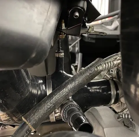
    Build your silicone intake tube like shown below. 3/4-3/4” barb goes into the 3/4" hole with a pinch clamp for the crank case breather or boost recirculating valve. If you have a catch can, you will cap this plug with the 3/4" silicone cap. The 3/16” barb will go into the 3/16” port with a pinch clamp. This is for your boost reference port. Slide the silicone intake tube onto the turbocharger inlet, fasten down with new hardware through the access panel.
  9. Step 9

    The inlet will line up directly with the OEM air intake shroud. Some plastic OEM shrouds are different so you can cut the turbo inlet silicone down to fit exactly to the OEM shroud.
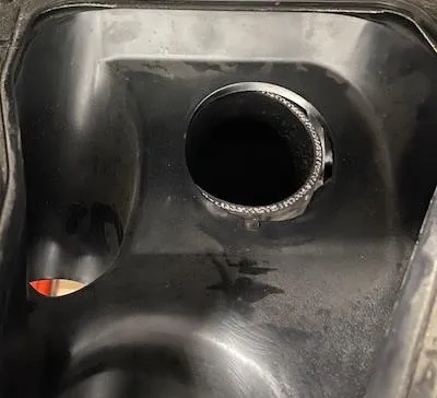
    The inlet will line up directly with the OEM air intake shroud. Some plastic OEM shrouds are different so you can cut the turbo inlet silicone down to fit exactly to the OEM shroud.
  10. Step 10

    Place the foam insert into the OEM plastic shroud. Place the reducer through the foam into the silicone, fasten down with supplied hose clamp.
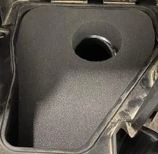
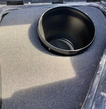
    Place the foam insert into the OEM plastic shroud. Place the reducer through the foam into the silicone, fasten down with supplied hose clamp.
    Place the foam insert into the OEM plastic shroud. Place the reducer through the foam into the silicone, fasten down with supplied hose clamp.
  11. Step 11

    Place filter onto the reducer, fasten down with the air filter clamp.
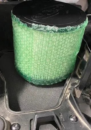
    Place filter onto the reducer, fasten down with the air filter clamp.
  12. Step 12

    Connect the boost solenoid hose and crank case hose to the silicone. Fasten down with a pinch clamp.

  13. Step 13

    Reinstall the turbo access cover and seat if removed. Reinstall the air filter cover and CVT ducts if they were removed.
Emissions notice. This product is exempt from the emission standards and related requirements of 40 C.F.R. § 1051 as provided by 40 C.F.R. § 1051.620, and California law [e.g., vehicle code §§ 27156 and 38391]. This product is sold only for use in connection with EPA certified, purpose-built, nonroad vehicles used solely for closed course, nonroad competition/racing and not used for any recreational purpose or on public highways or right of ways maintained by and open to the public. This product is sold only in connection with machines that do not fall under state and/or federal noise or emission standards/regulations. Purchasers who/that purchase this product represent and warrant that the product is purchased only in connection with EPA-certified, emission-regulations-exempt and noise-regulations-exempt competition/racing vehicles as interpreted under applicable state and/or federal law.

Need technical support?

Submit a ticket with your vehicle and what you're seeing, and our support team will get back to you.

Contact Support
We use cookies to improve your experience on our website. Read about how we use cookies in our Privacy Policy. By browsing this website, you agree to our use of cookies. privacy policy
accept

Your cart

×
×