 BUY NOW, PAY LATER. Starting at 0% APR


Polaris RZR Surge Tank Kit
Polaris RZR Surge Tank Kit
In the box
Parts and tools
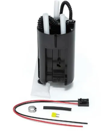
Included parts
- 1EVP Surge Tank Assembly
- 120amp Mini Fuse
- 113.3mm Pinch Clamp
- 12” Heat Shrink
- 112v Connector Pigtail
Required tools
- EVP Fuel Pump Tool
- Knife
- Solder Gun
- Heat Gun
- Pinch Clamp Tool
Procedure
Installation
- Step 1
Remove the OEM fuel pump assembly out of your vehicle. It will be located underneath the passenger seat (back passenger seat if 4-seater). DO NOT break the green/blue safety clips holding the fuel lines on. It is easiest to remove the fuel pump assembly nut with EVP tool (953RU0305).
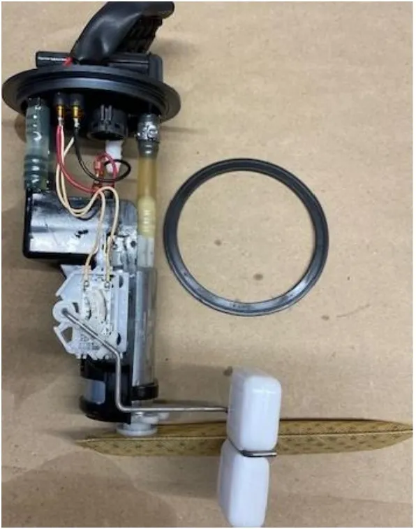
XP Turbo/S OEM Assy 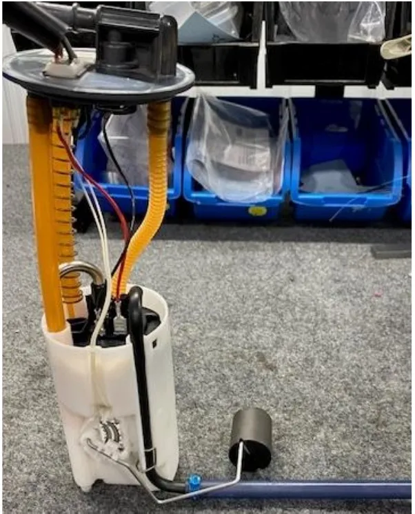
Pro XP/Turbo R OEM Assy - Step 2
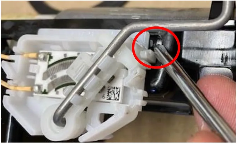
Remove the float sending unit from the OEM fuel pump. On the XP Turbo/S assembly use a small screwdriver to push the black clip inward, push the sending unit upward. On a Pro XP/Turbo R use a small screwdriver and push the sending unit downward. Remove.
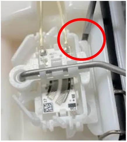
- Step 3
Cut (3) hoses attached to the fuel hat. (2) white hoses are supports and (1) hose is for the fuel pump. If there is a pitch clamp, remove that as well. On the Pro XP/Turbo R assembly you will NOT reuse the spring.
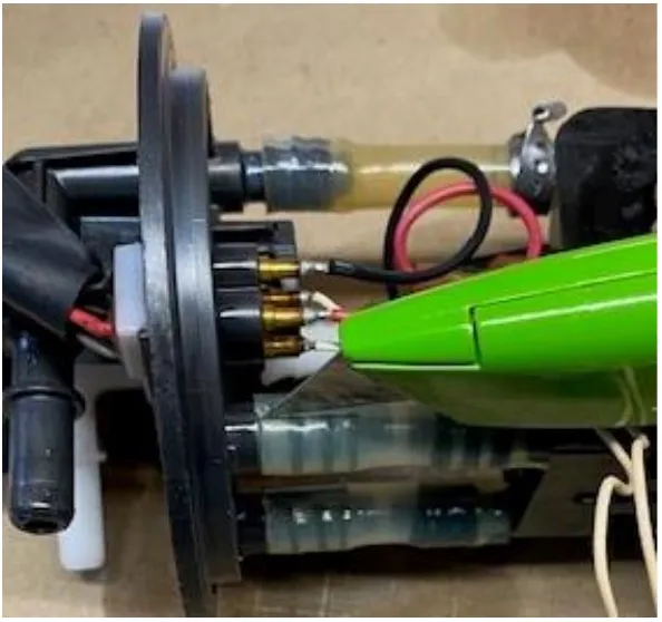
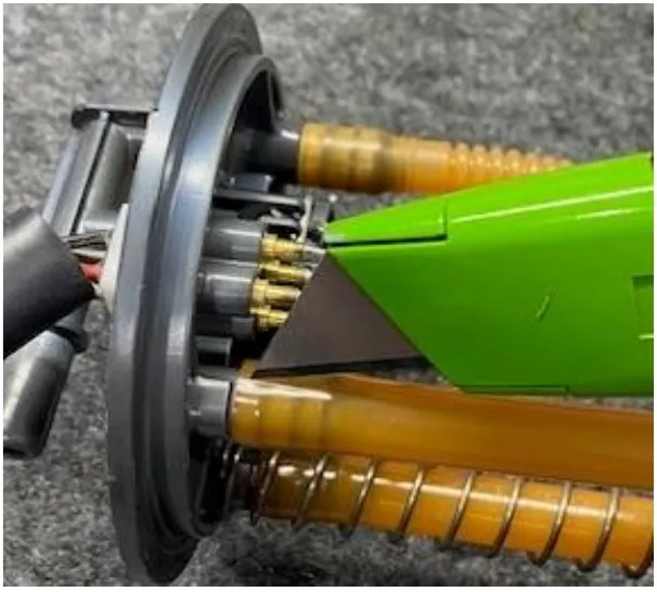
- Step 4
Remove the positive and ground wire from the pump. You can now remove the OEM fuel hat assembly from the fuel pump.
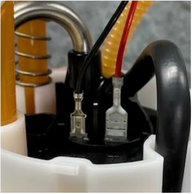
- Step 5
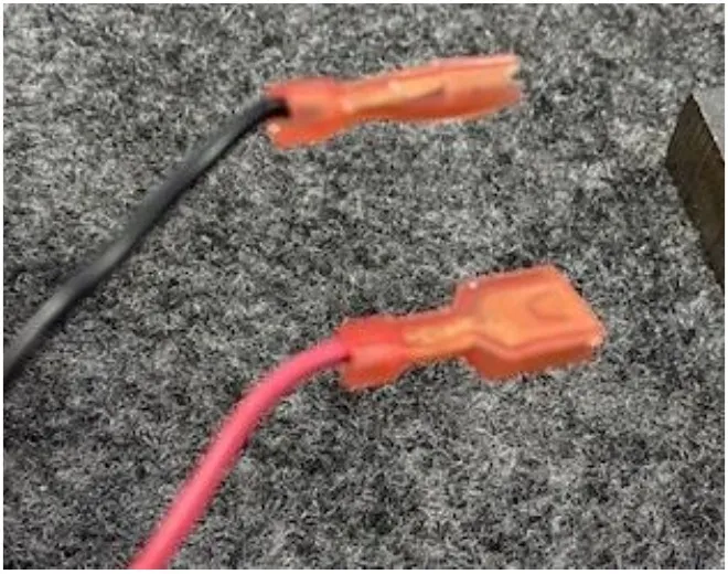
Cut the OEM power and ground terminals off from the fuel hat. Measure how much wire you will need to cut off the supplied pig tail connector.
- Step 6
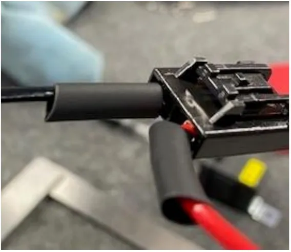
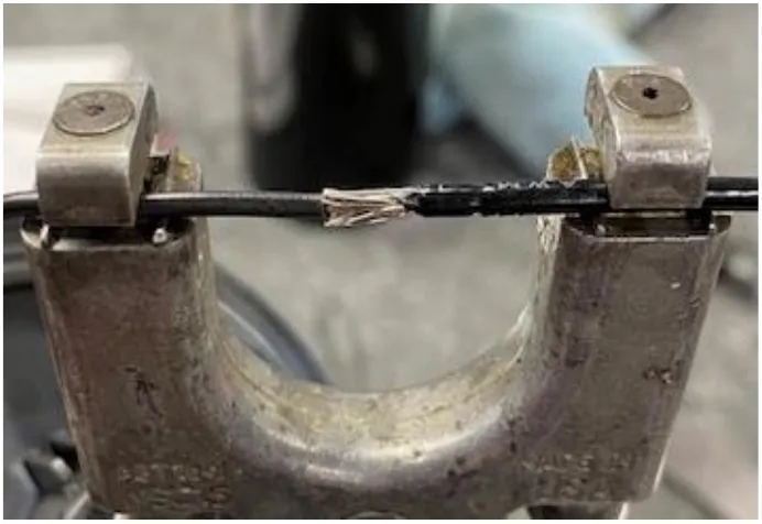
Cut the supplied heat shrink in half, you should only need 1” per wire. Slide heat shrink onto each wire. Solder black to black and red to red.
- Step 7
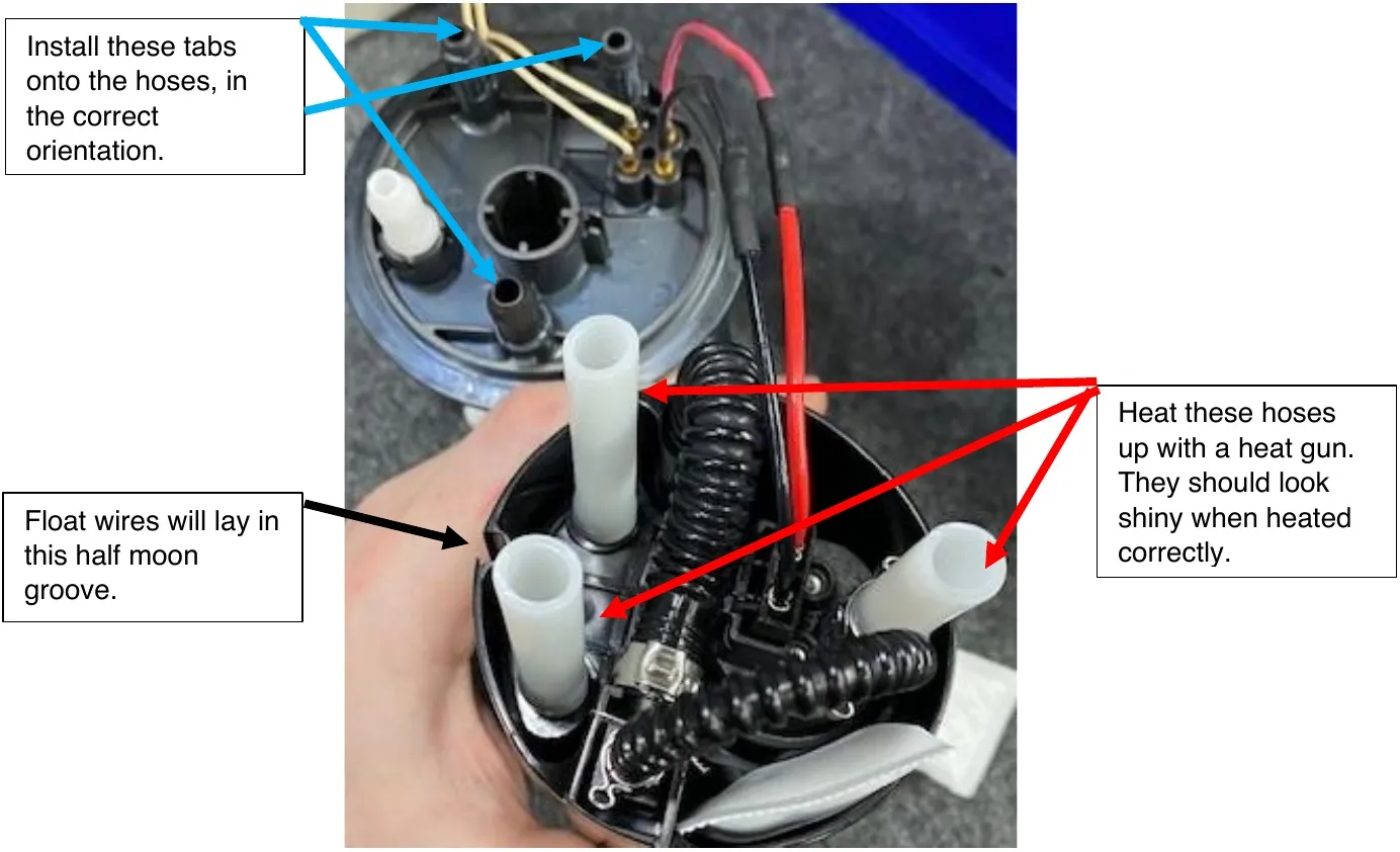
Connect the solder connector to the pump. It will click once installed all the way. Install the supplied 13.3mm pinch clamp onto the fuel pump hose. If XP Turbo/S assembly, you will need to heat up all (3) hoses equally until they look shiny (DO NOT OVER HEAT). (If Pro XP/Turbo R assembly, you can install the black corrugated fuel hose first with a 13.3mm pinch clamp and install the supports together.) Once all (3) hoses are heated install the fuel hat barbs onto the white hoses. Make sure the float wires are in between both support hoses, they will lay in the half moon on the surge tank. MAKE SURE all (3) hoses are pressed on all the way!
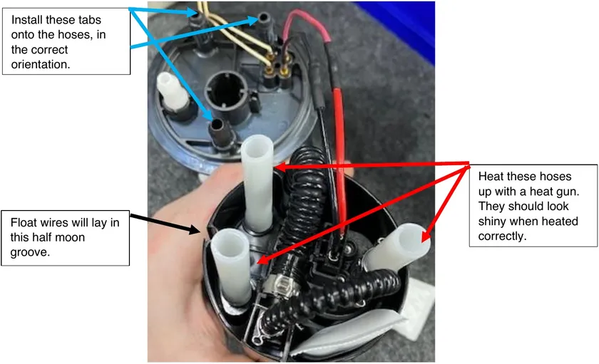
Install these tabs onto the hoses, in the correct orientation. Heat these hoses up with a heat gun. They should look shiny when heated correctly. Float wires will lay in this half moon groove. 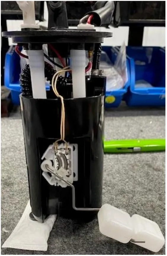
XP Turbo/S Assembly 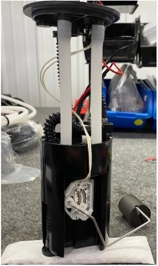
Pro XP/Turbo R Assembly
Procedure
Installing the EVP Surge Tank Assembly
- Step 1
Double check all hoses, clamps, float, and wiring harness before installing. Make sure to reuse the OEM circle gasket between the fuel hat and fuel tank.
- Step 2
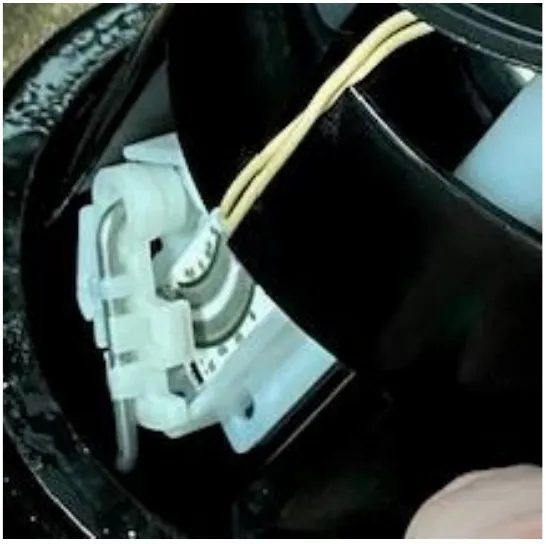
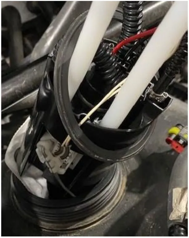
Always install the fuel float first and fuel sock second. You can also remove the float arm from the assembly and install into the tank. Install the surge tank into the fuel tank about 2.0”. Then reinstall the float arm to the float assembly. See below.
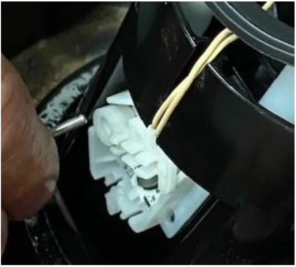
- Step 3
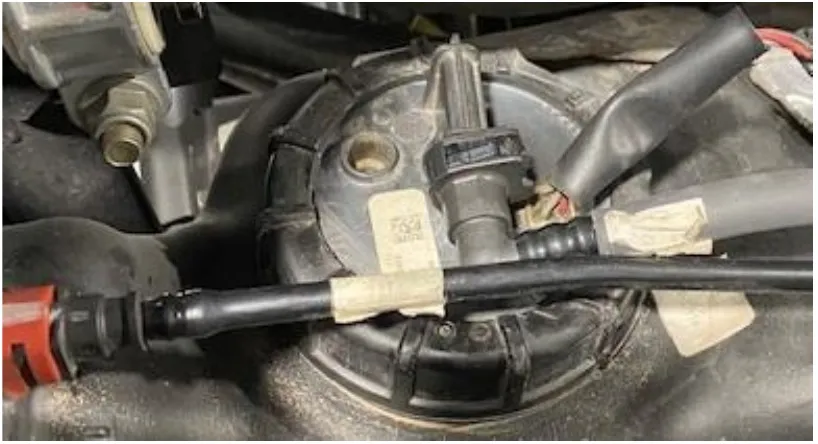
Install the O-ring gasket between the fuel tank and fuel hat. Install the fuel pump nut and keep the same orientation if it is a XP Turbo/S model. If a Pro XP/Turbo R you will flip the fuel hat orientation 180-degrees. This will allow your float to read properly. You may need to clock your fuel line in the OEM holder.
Pro XP/Turbo R Assembly Orientation - Step 4
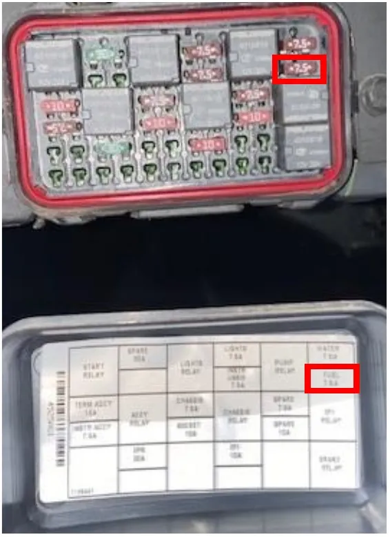
Locate your fuse box (underneath steering wheel). Remove the fuel pump fuse and install supplied 20amp fuse.
Need technical support?
Submit a ticket with your vehicle and what you're seeing, and our support team will get back to you.
