 BUY NOW, PAY LATER. Starting at 0% APR


Parts Included in Paragon 43-270 Turbo Upgrade System
Polaris 2017-2021 XP Turbo/S Paragon-43 270 & 280 Turbo Upgrade System
2017-2021 XP Turbo/S Paragon-43 270 & 280 Turbo Upgrade System
Before you start
Note
Expect 24–48-hour delay from the time you request a tune to when the file is enabled. Please create your Maptuner/CodeShooter account before starting the project.
This is a high-performance upgrade!
Although we have gone through great lengths to build safety into the upgrade turbo system, the fact is installing any upgrade / turbo system requires care in both operation and installation. Poor fuel, improper setup or any number of things that are done incorrectly can damage your engine!
- You have likely voided the sound and exhaust emission standards of your country if applicable.
- This upgrade is intended for OFFROAD and RACING use only.
- This is a performance upgrade which will VOID your engine warranty especially if installed incorrectly or operated without regard to your instruments.
- The fuel requirements must be adhered to. Poor fuel can destroy an engine in seconds.
- Evolution Powersports bears no responsibility for damage caused to your vehicle by the installation of EVP products. The warranty on big turbo kits is 30 days from the date of purchase. Evolution Powersports, at its discretion will determine whether a part meets the warranty requirements. In no case is there any warranty from EVP for your vehicle or vehicles drivetrain. Although we have been careful to supply you with the highest quality parts possible, we assume no liability for damage to the vehicle or personal injury from installing or using any of our products.
- The installation of this kit is technical and mechanical in nature with many opportunities to make mistakes – mistakes that can be very costly. If you are not qualified to install this kit, bring your vehicle to one of our qualified installation centers to do the installation.
- This kit will make your vehicle faster, climb higher and accelerate more quickly and take a longer distance to brake than a stock tuned vehicle. If you are not capable of controlling the vehicle with the added performance, do not install the kit.
- High boost is hard on spark plugs – they must be changed frequently. If you experience misfire issues – Gap and replace the spark plugs.
- A full exhaust and clutching are required for this kit and can be purchased separately.
- Do not ever allow a child or an unqualified driver to operate this vehicle.
In the box
Parts and tools
| 100FP0020 | XP Turbo/S & Pro XP & Turbo R Silicone Charge Tube Kit, Black |
| 100FP0117 | XP Turbo/S & Pro XP & Turbo R Blow Off Valve 2.0 (BOV) Kit |
| 203FP0093 | XP Turbo/S P43 V-Flow Boot Kit, Black |
| 500FP0005 | 2017-2021 XP Turbo/S High Pressure Fuel Pump Kit |
| 502FP0003 | XP Turbo/S / Pro XP 1300CC Injector Set of 2 |
| 604FU0053 | 2016-2021 XP Turbo/S NON EVAP Paragon 43/42 Blue Turbocharger Assembly |
| 604FP0024 | XP Turbo/S Paragon Install Kit |
| 707FP0003 | Maptuner X for Polaris |
| 800FP0001 | XP Turbo/S XR Series EVP Head Stud Kit |
| 804FP0169 | XP Turbo/S Spark Plug Set Of 2, Brisk |
| 804FP0190 | Pro XP and Turbo R TPR Oil Breather Kit, Raw |
Parts Included XP Turbo/S Paragon Install Kit
| 953RU0078 | Hps 3/8" Silicone Water Hose | 26 |
| 953RU0078 | Hps 3/8" Silicone Water Hose | 26 |
| 953RU0127 | 22mm Pinch Clamp | 4 |
| 953RU0197 | Reduction T 1/2" Barb x 3/8” Barb | 2 |
| 953RU0157 | 19.2mm Pinch Clamp | 4 |
| 953RU0121 | M6 x 1.0 x 14mm socket head screw SS | 2 |
| 953RU0141 | M6 SS Washer | 2 |
| 001FU0133 | Paragon Maptuner Power Flash | 1 |
| Level | Tunes | Max Boost (psi) | Spark Plug Gap | Spring | Waste Gate (psi) | Engine HP |
|---|---|---|---|---|---|---|
| P43-270 | 91, 110, E85 | 18, 28, 28 | .016 - .018 | Brown/Grey | 6 | 270 (E85) |
Required Parts (Sold Separately)
Required accessories
- EVP or other Full Turbo Back Exhaust System
- AFR Module
- Boost Module
Parts Included in Paragon 43-280 Turbo Upgrade System
| 100FP0020 | XP Turbo/S & Pro XP & Turbo R Silicone Charge Tube Kit, Black |
| 100FP0117 | XP Turbo/S & Pro XP & Turbo R Blow Off Valve 2.0 (BOV) Kit |
| 203FP0093 | XP Turbo/S P43 V-Flow Boot Kit, Black |
| 500FP0031 | 2019-2021 XP Turbo/S EVAP 340LPH High Pressure Fuel Pump Kit |
| 502FP0016 | XP Turbo/S / Pro XP 1700CC Injector Set of 2 |
| 604FU0054 | 2019-2021 XP Turbo/S & Pro XP EVAP Paragon 43/42 Blue Turbocharger Assembly |
| 604FP0024 | XP Turbo/S Paragon Install Kit |
| 707FP0003 | Maptuner X for Polaris |
| 800FP0001 | XP Turbo/S XR Series EVP Head Stud Kit |
| 705FP0030 | RZR 4 Bar MAP Sensor Kit |
| 804FP0169 | XP Turbo/S Spark Plug Set Of 2, Brisk |
| 804FP0190 | Pro XP and Turbo R TPR Oil Breather Kit, Raw |
Parts Included XP Turbo/S Paragon Install Kit
| 953RU0078 | Hps 3/8" Silicone Water Hose | 26 |
| 953RU0078 | Hps 3/8" Silicone Water Hose | 26 |
| 953RU0127 | 22mm Pinch Clamp | 4 |
| 953RU0197 | Reduction T 1/2" Barb x 3/8” Barb | 2 |
| 953RU0157 | 19.2mm Pinch Clamp | 4 |
| 953RU0121 | M6 x 1.0 x 14mm socket head screw SS | 2 |
| 953RU0141 | M6 SS Washer | 2 |
| 001FU0133 | Paragon Maptuner Power Flash | 1 |
| Level | Tunes | Max Boost (psi) | Spark Plug Gap | Spring | Waste Gate (psi) | Engine HP |
|---|---|---|---|---|---|---|
| P43-280 | 91, 100, 110, E85 | 19, 25, 29, 29 | .016 - .018 | Brown/Purple | 8 | 280 (E85) |
Required Parts (Sold Separately)
Required accessories
- EVP or other Full Turbo Back Exhaust System
- AFR Module
- Boost Module
Procedure
Installation
Note
Although the kit can be installed without removing the bed, it is highly recommended to remove it for better access.
- Step 1
With a 10mm socket remove the heat shields over the top of the engine and heat shields attached to the header/turbocharger.
- Step 2
With an 11mm socket remove OEM charge tube, intake pipe and airbox.
- Step 3
Soak the bolts holding the down pipe (turbo exhaust pipe) to the turbocharger with PB Blaster or other penetrating lubricant and let sit for 30 minutes, then remove and clean with a shop rag. Save gasket.
- Step 4
Remove oil drain hose from turbocharger, but leave it connected to the engine.
- Step 5
Label the vacuum lines going to the wastegate actuator and compressor cover turbo port and disconnect from turbocharger.
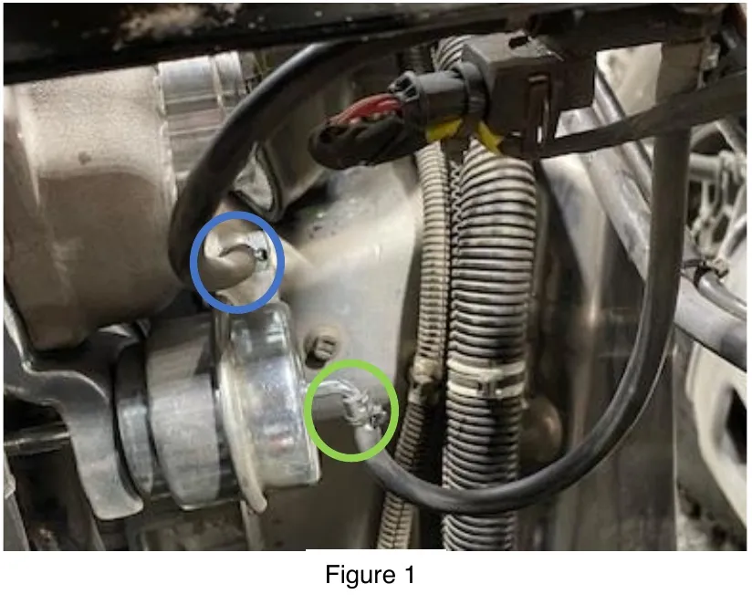
- Step 6
Remove the 13mm oil supply banjo bolt from the top of the OEM turbo. Make sure to save both copper washers as well as the banjo bolt.
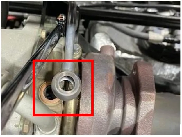
- Step 7
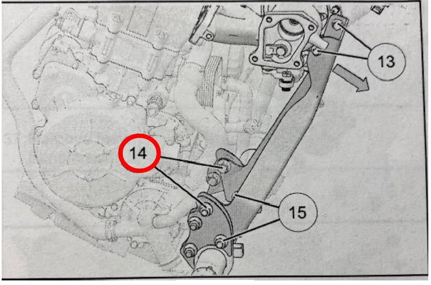
Remove the (2) fasteners connecting the turbo support bracket to the top of the turbocharger. Loosen the bottom (6) fasteners but only remove #14 shown below. Remove the oil feed line from the turbo support bracket. Remove the turbo support bracket from the vehicle.
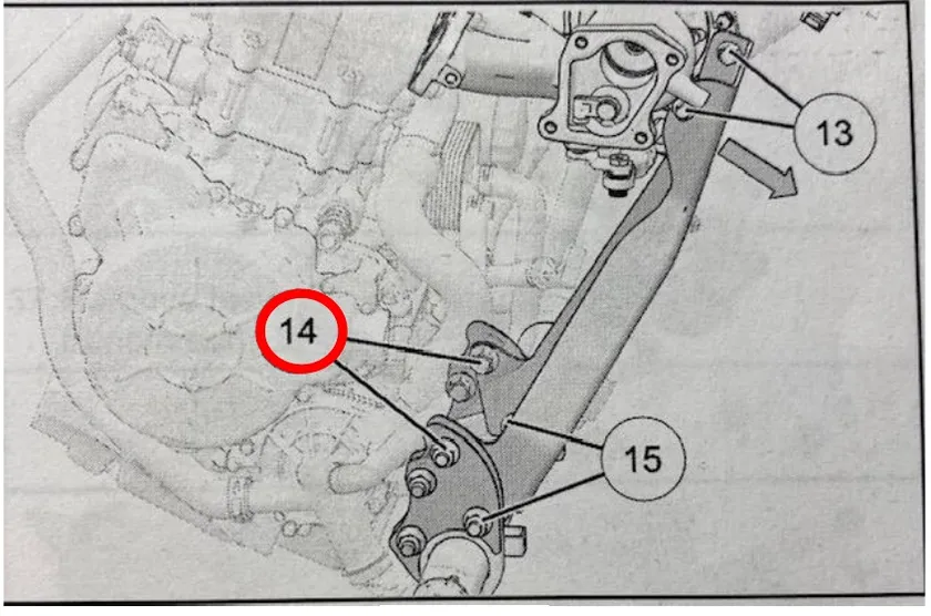
- Step 8
Remove (4) 13mm nuts holding the turbocharger to the block. Remove (2) M6 Allen screws holding the turbocharger to the block. Remove turbocharger from the vehicle.
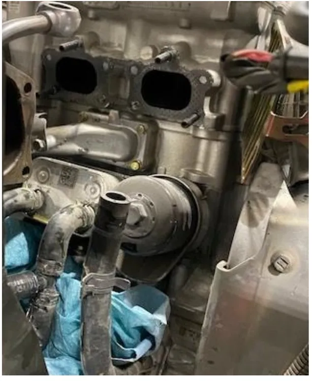
Figure 4 - Step 9
Remove the OEM oil drain tube from the OEM turbocharger and install onto EVP turbocharger. Use supplied gasket. Torque to 11 ft/lb.
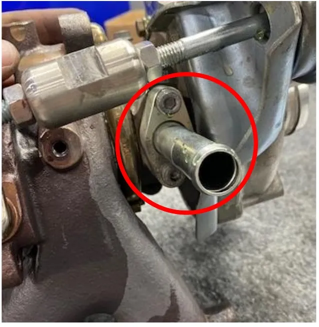
Figure 5 - Step 10
On the turbo support bracket, you will need to grind a larger radius around the top support hole. See photo below where the mark is located.
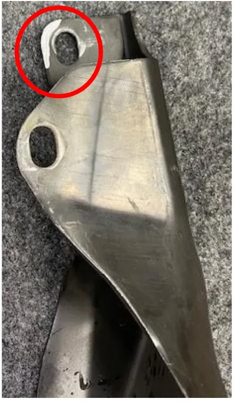
Figure 6 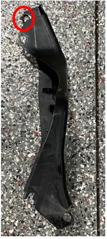
Figure 7 - Step 11
You will also need to grind a radius around the wastegate location on the turbo support bracket. See photo below.
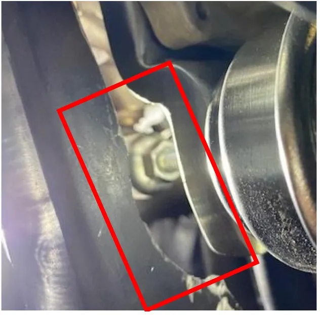
- Step 12
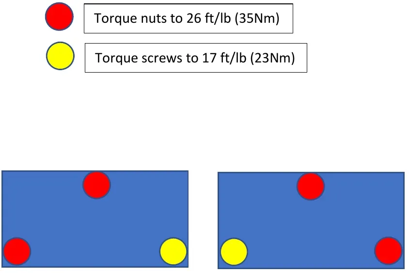
Install the new turbocharger, if the head pipe gasket is damaged you must replace it. Torque specifications are below for turbo.
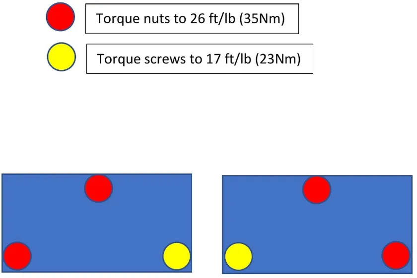
Torque nuts to 26 ft/lb (35Nm). Torque screws to 17 ft/lb (23Nm) 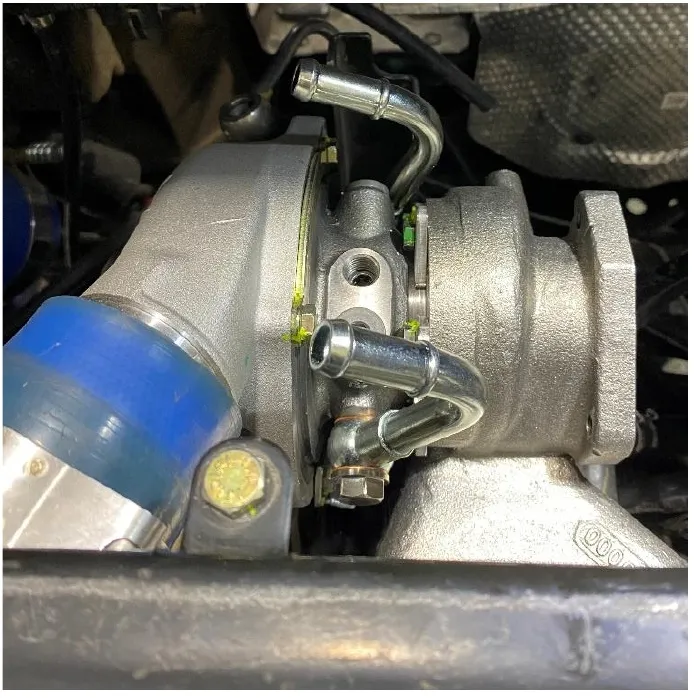
- Step 13
Install the turbocharger support bracket back into the car and check fitment before you bolt it back into place. Once fitment is correct, re use all OEM hardware. Torque lower turbocharger support bracket bolts to 42 ft/lb.
- Step 14
Install the oil line into the turbocharger. Reuse both copper washers and banjo bolt. Torque to 33 ft/lb. Install both 26” turbo coolant lines onto the turbo “J” coolant fittings. Clamp them both with 19mm pinch clamps.
NoteIt is easier to slide the pinch clamp onto the fitting first, then the coolant hose.
- Step 15
Install the (2) supplied “T” fittings into the coolant hoses leading to the oil cooler. The 3/8” fittings will slide into the OEM coolant hoses, clamp with (2) 22mm pinch clamps per hose. (Figure 10).
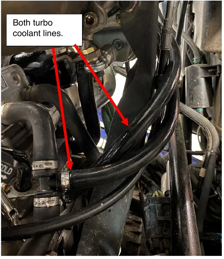
Figure 10 - Step 16
Route the (2) turbo coolant lines around the turbo and down to the “T” fittings. Slide both hoses onto the 3/8" fitting. Clamp with supplied 19mm clamps. (Figure 11).
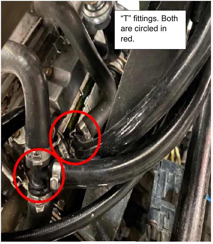
Figure 11 - Step 17
Reinstall the OEM rubber oil drain hose to the oil drain pipe.
Procedure
Injector Removal
- Step 1
With the engine cold, spray the injector valleys and fuel rail with parts cleaner. Use compressed air to finish. If you don’t do this step and you remove the injectors, debris will fall into the engine and plenum.
- Step 2
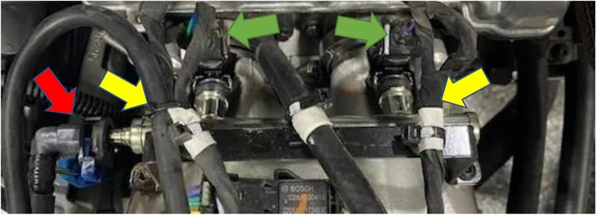
Remove the plastic safety retainer on the fuel rail. Remove the fuel line from the fuel rail (red arrow). Fuel may seep out of the fuel rail, and have rags close by.
- Step 3
Remove the injector electrical adaptors (green arrow) and loosen the (2) fuel rail screws (yellow arrow). Remove the fuel rail with injectors attached.
- Step 4
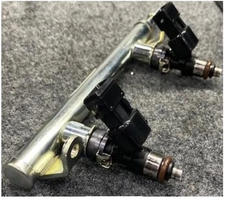
Remove the old injectors and place in a plastic bag. Use dielectric grease on the O- rings on the new injectors and slide into the fuel rail.
- Step 5
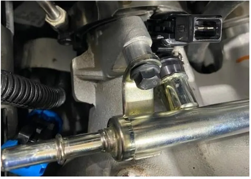
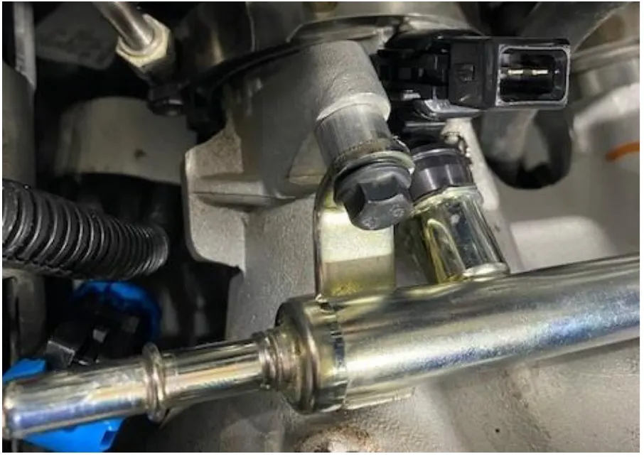
Reinstall the fuel rail with supplied hardware. Place the spacers between the fuel rail and plenum. Torque down to 7 ft/lb.
 Note
the injectors will still move when torqued down, this is correct. They are sealed.
- Step 6
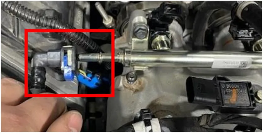
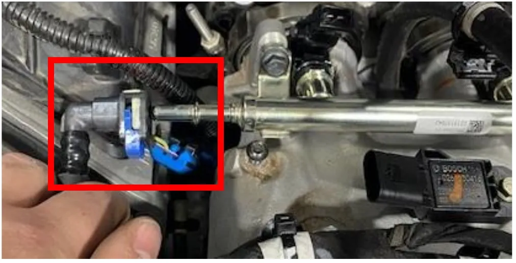
Reinstall the fuel hose to the fuel rail. Make sure the fuel line is all the way on.

Procedure
Head Stud Installation
- Step 1
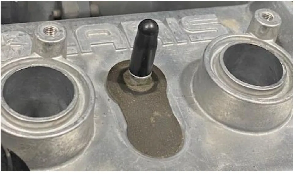
Pinch off all coolant lines going to the engine and valve cover. Remove the coolant reservoir cap if you haven’t done that already. Once all coolant lines are pinched off remove the valve cover coolant line.
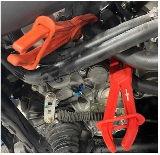
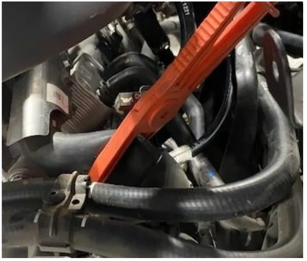
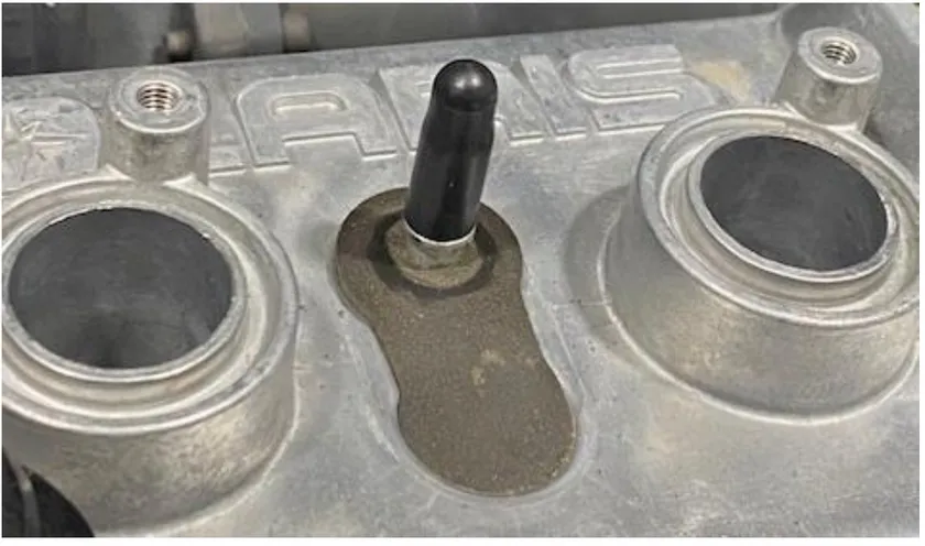 Caution
there may be pressure behind this hose, cap the barb off with a silicone cap.
- Step 2
Disconnect the spark plug coil packs and loosen the coil packs with a 8mm socket. Pull the coil packs out of the valve cover.
- Step 3
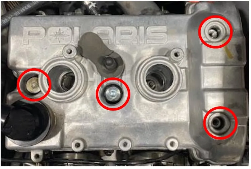
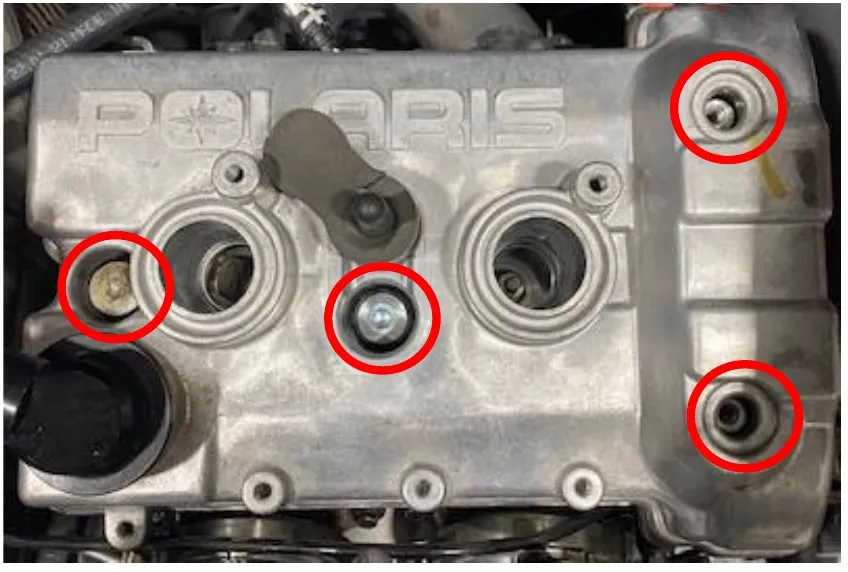
Remove the (4) valve cover screws using a T-40 torxs. Keep the rubber gromets. Remove the valve cover and gasket.
- Step 4
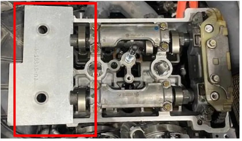
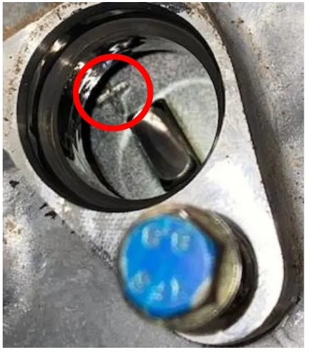
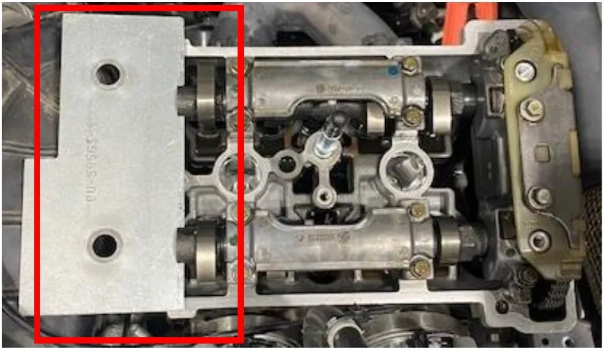
Remove the crankcase position sensor using an 8mm socket. Find TDC and slide the cam locking tool into place. Tool Number: PU-50563-1. To double check TDC you can find a (+) sign looking through the crankcase position sensor port.
- Step 5
Remove the cam chain tensioner using a M6 Allen. Check gasket for any tears.
- Step 6
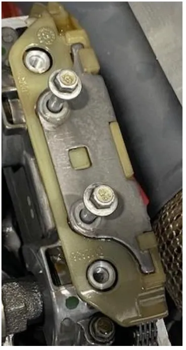
Remove the (2) retaining bolts holding the top guide in place, using a 8mm socket.
- Step 7
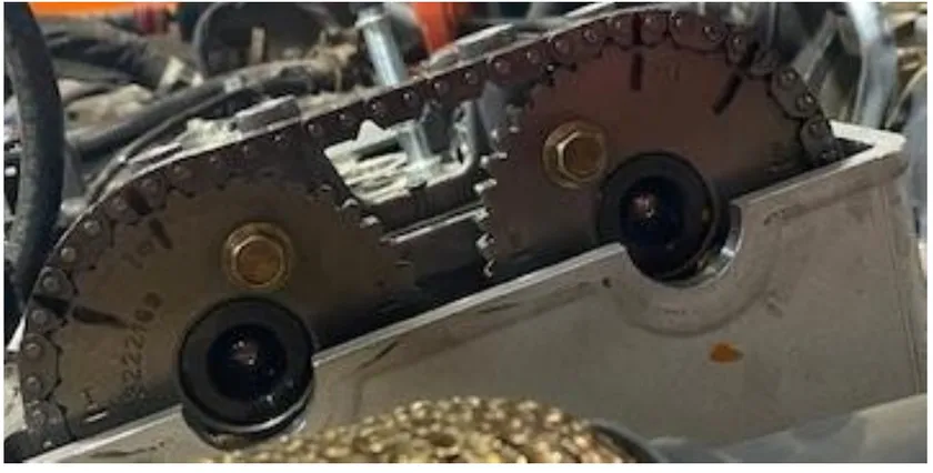
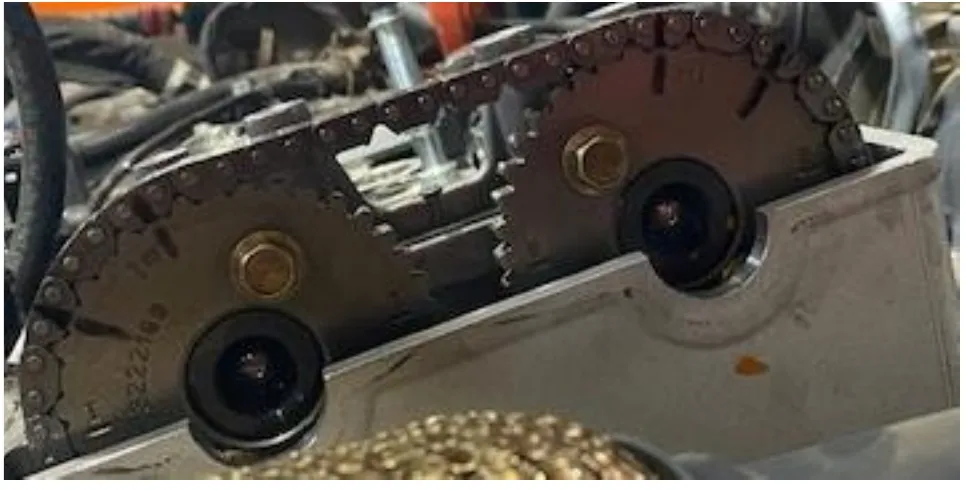
Clean the cam sprockets and chain. With a sharpie make (2) marks on each gear and chain for installation purposes.
- Step 8
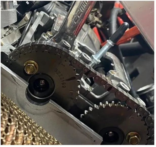
Place a 22mm wrench on the intake cam, spin the clutch to release pressure off the valves while loosening the intake cam sprocket. Remove the sprocket once hardware is removed.
- Step 9
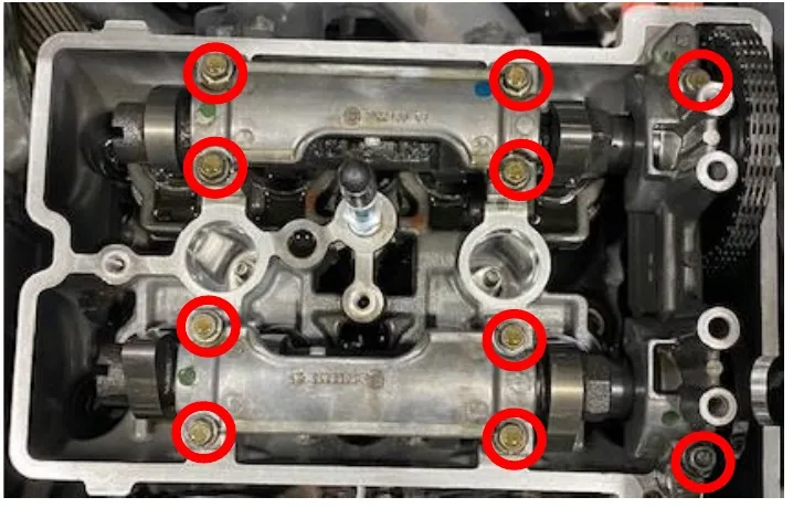
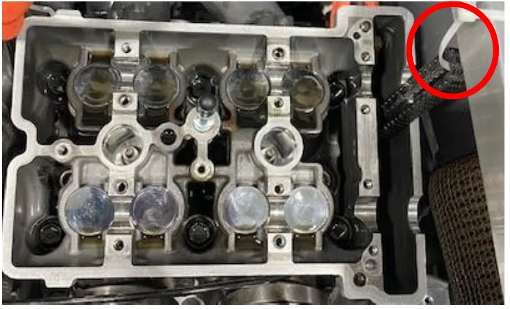
Loosen both camshaft carriers using a 8mm socket. Remove carriers and cam shafts from the engine. Zip tie the cam chain up to the bed mount so the chain doesn’t come off the crank.
- Step 10
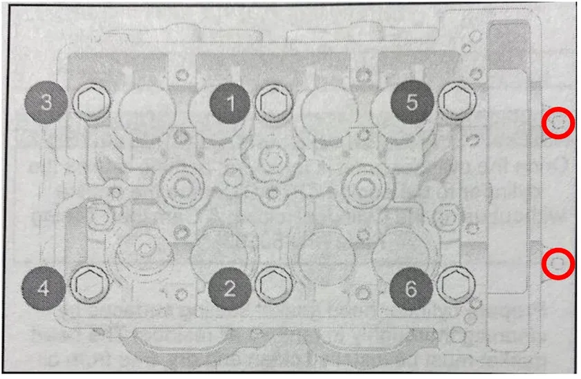
Remove one head bolt and replace it with a stud at a time so the cylinder head never has more than one bolt/stud loose at a time. Lather both ends of the stud with supplied ARP assembly lube. Hand tighten the stud until it bottoms out. Place assembly lube on both sides of the washer, place the washer on the stud. Finger tighten the nut onto the stud and torque to 50 ft/lbs. See torque sequence and specifications below.
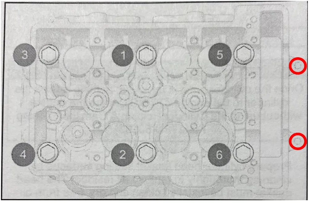
| Torque Specification: Head Stud | 11mm ARP 2000 | 11mm ARP 625 |
|---|---|---|
| Step 1 | 50 ft/lb | 50 ft/lb |
| Step 2 | 68 ft/lb | 72 ft/lb |
| Step 3 | 85 ft/lb | 95 ft/lb |
| Torque Specification: M6 Outer Bolts | 11mm ARP 2000 | 11mm ARP 625 |
|---|---|---|
| Step 1 | 10 ft/lb | 10 ft/lb |
Note
On final torque go over the pattern a total of (3) times.
- Step 11
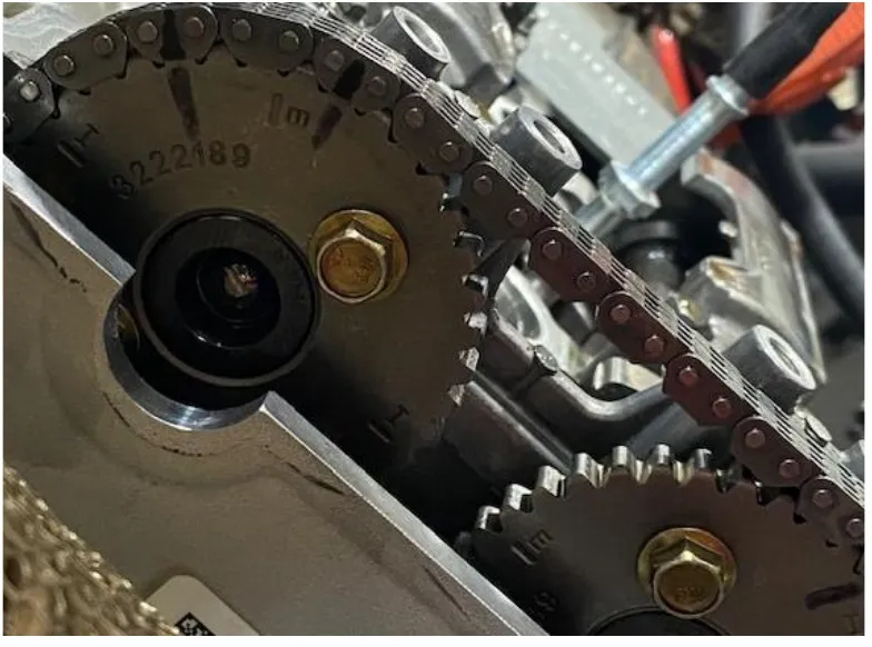
Reinstall the camshafts and camshaft carriers. Snug up the camshaft carriers. Install cam shaft timing plate back into the camshafts. Verify TDC mark on the flywheel making sure the engine is still timed. Install the intake sprocket back onto the intake camshaft. Make sure your sharpie marks align properly. Apply red Loctite to the sprocket hardware and torque camshaft sprocket to 14 ft/lb. Reinstall the outer camshaft carrier and chain guide. Torque all camshaft carrier bolts to 7 ft/lb.
- Step 12
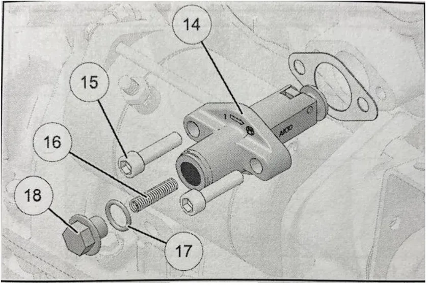
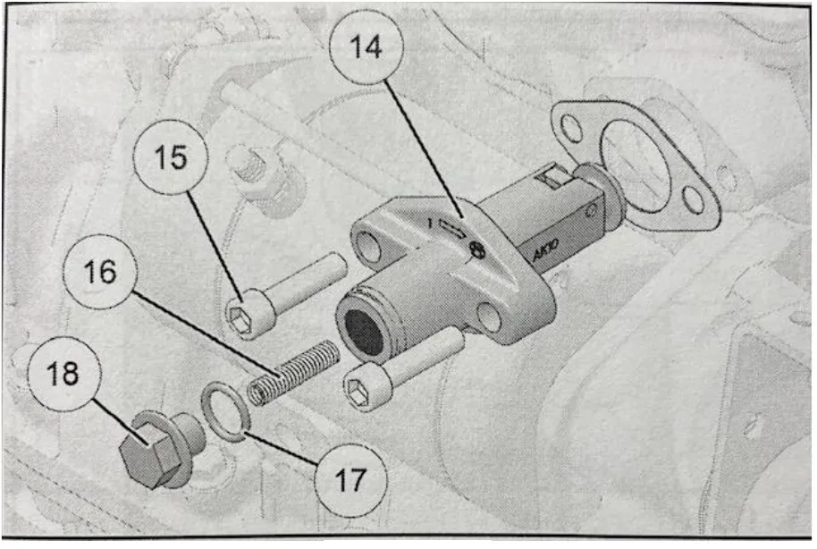
Remove the spring retainer bolt out of the spring tensioner and push the adjuster all the way in. Install the cam chain tensioner into the block and torque the mounting bolts to 7 ft/lb. Install the tensioner spring, washer and retainer bolt. Torque spring tensioner bolt to 12 ft/lb.
- Step 13
Rotate the crankshaft two full revolutions to verify camshaft timing.
- Step 14
Reinstall the valve cover gasket, place a silicone based liquid gasket around the two lobes before installing. Place the valve cover over the camshafts and torque (4) valve cover screws to 7 ft/lb.
- Step 15
Remove the spark plugs and install supplied EVP spark plugs. EVP gapped plugs are .016-.018”. Torque plugs to 9 ft/lb.
Procedure
Charge Tube & V-Flow Installation
- Step 1
Install the supplied 4 bar MAP sensor into the charge tube. Apply dielectric grease to the O-ring for installation. Use suppled M5 screw to fasten down MAP sensor. Install the charge tube onto the turbocharger and throttle body. Reuse OEM hardware, use an 11mm deep well socket. Install EVP blow off valve or boost recirculation valve. Run supplied vacuum hose back to the plenum barb and “T” into the OEM hose.
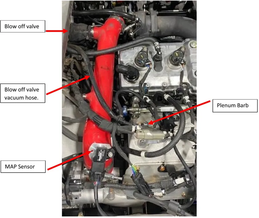
- Step 2
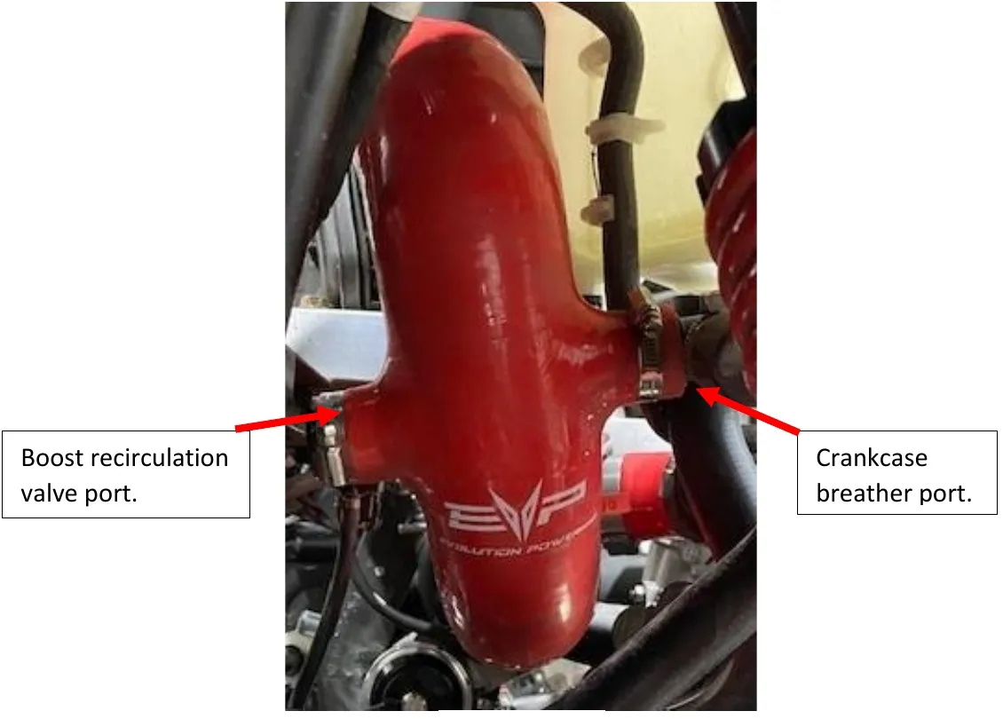
Before installing the EVP V-Flow its easier to block off the crankcase vent and boost recirculating valve ports before installation. If you aren’t running a catch can or blow off valve you can keep the ports open. Install the V-Flow onto the turbocharger and air box. Tighten down with a 11mm socket. Reinstall the OEM MAF sensor in the stock location.
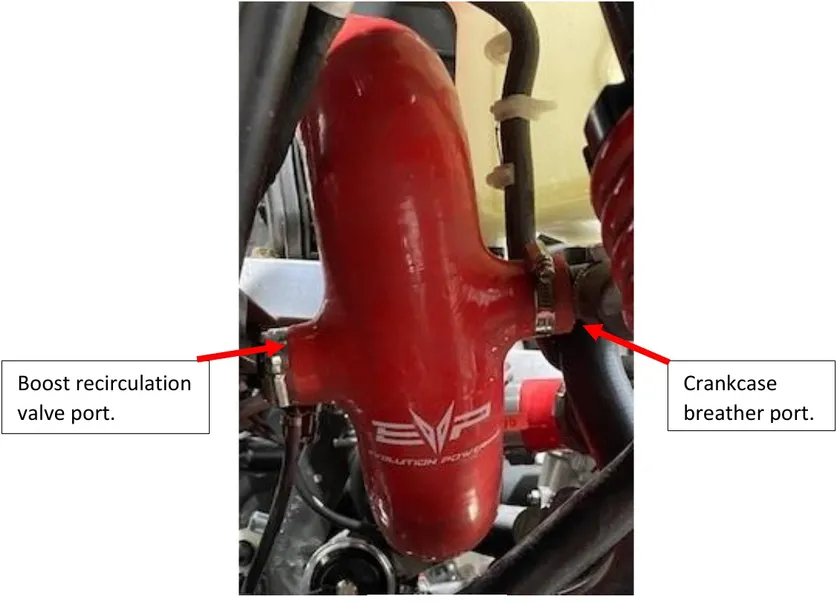
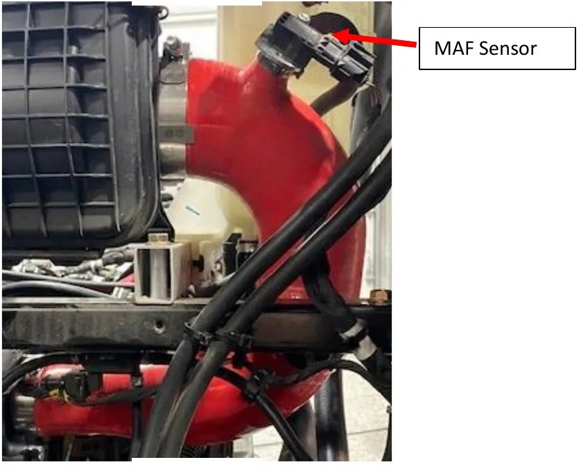
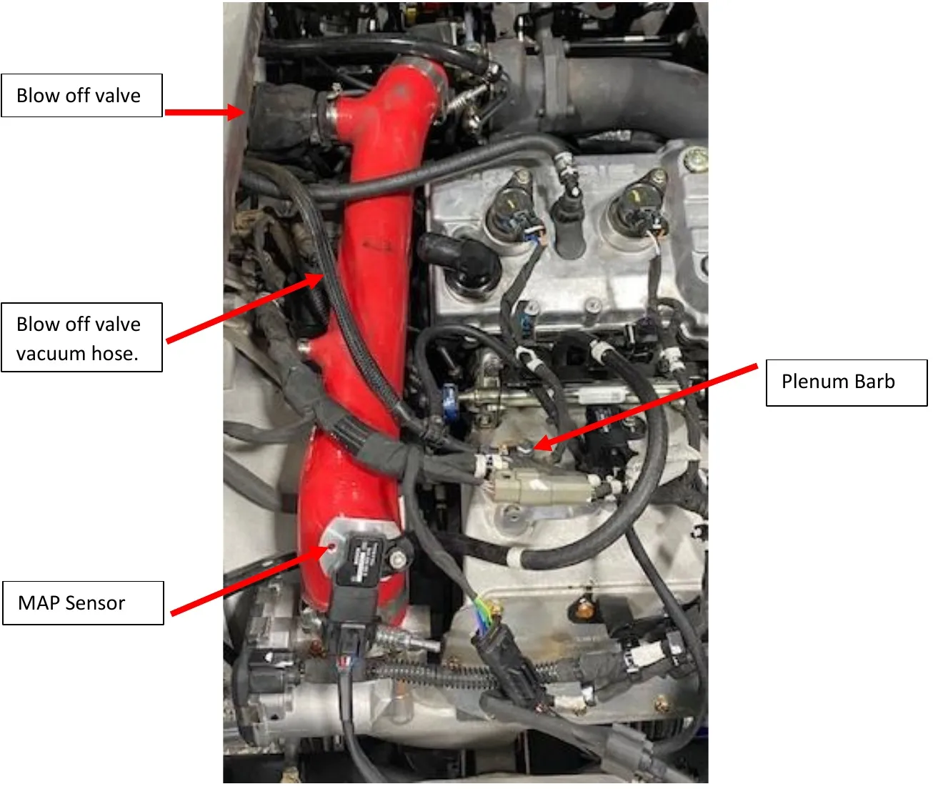
Procedure
Heat Shield Installation
- Step 1
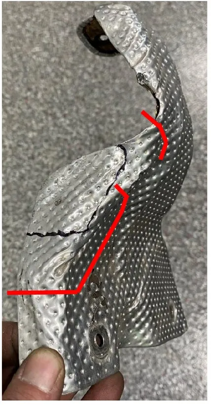
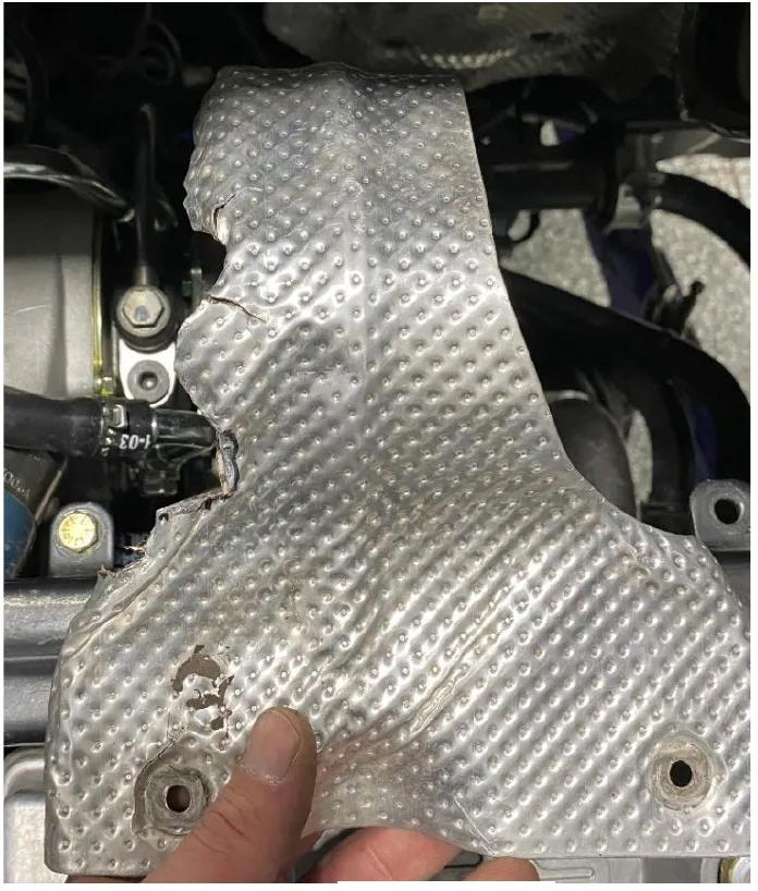
Grab the turbo heat shield, you will have to grind (2) areas away now that the turbo has coolant lines. See figure 4-5.
- Step 2
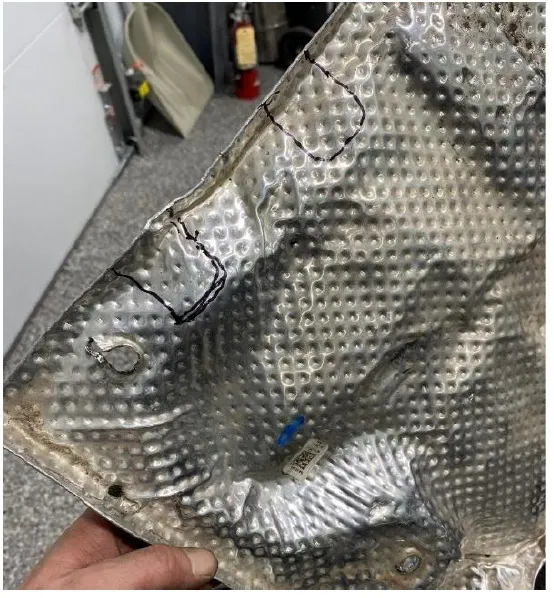
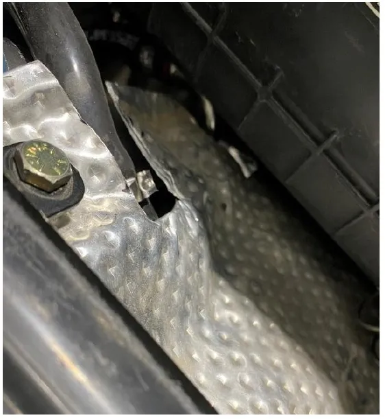
Grab the exhaust to bed heat shield, you will need to make square cut outs on it for the new turbo coolant hoses to pass. See figure 6-7.
Procedure
Fuel Pump Installation
- Step 1
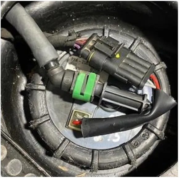
Find the fuel pump assembly underneath the passenger seat (rear passenger seat on a 4 seater). Remove the 4 pin connector and fuel hose retaining clip (sometimes blue or green). It is best to use EVP fuel pump tool 953RU0305 so you don’t mar up the nut.

- Step 2
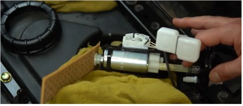
Genteelly remove the entire fuel pump assembly. Turning the pump at a 90-degree angle will help not damage the float and pre pump filter while removing.
- Step 3
Once the OEM fuel pump assembly is removed, place it on a clean dry surface. With a flathead screwdriver, remove the OEM pre filter. Also remove both positive (+) and negative (-) terminals off the OEM fuel pump.
- Step 4
With a razor blade, cut the hose down the ribs of the OEM fuel pump fitting. Do the same on the assembly side. Remove the hose completely and discharge.
- Step 5
Pull the top of the fuel pump away from the fuel pump assembly and push up on the bottom of the fuel pump, and the pump will release. Now the fuel pump assembly stands alone.
- Step 6
Install the 3 1/8” fuel hose onto the AEM fuel pump. Fasten down with a 14.5 pinch clamp.
- Step 7
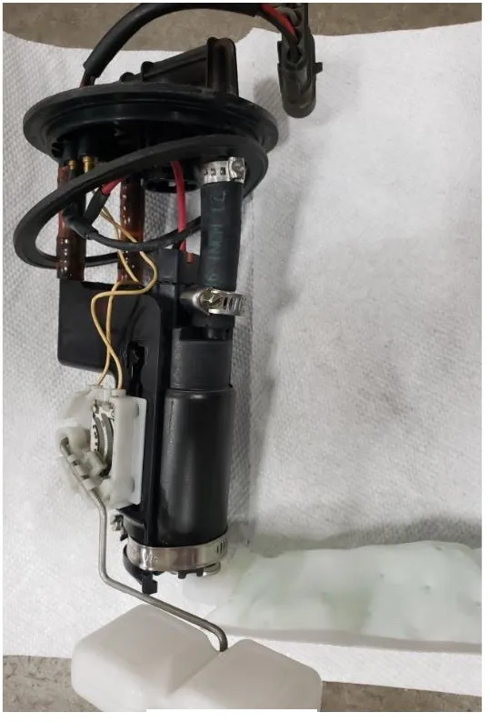
Install the AEM fuel pump back into the OEM assembly. This is a direct replacement for the OEM fuel pump. Push the pump down until it seats into the fuel pump assembly. Slide the second 14.5 pinch clamp onto the fuel hose and connect it to the fuel pump assembly. Clamp it down.
- Step 8
Reconnect the positive (+) and negative (-) terminals onto the AEM fuel pump. The positive (+) terminal is larger than the negative (-) so they can only go on one way.
- Step 9
Install the new pre filter onto the bottom of the AEM fuel pump.
- Step 10
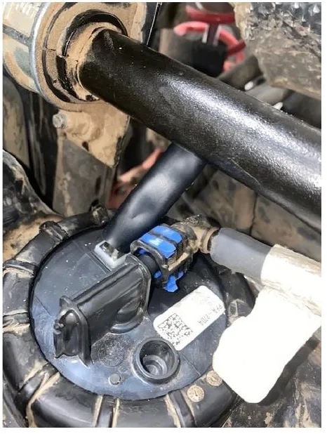
Start by holding the fuel pump assembly at a 90- degree angle. Place the float and filter in the tank first. Slide the rest of the assembly into the tank. Make sure the O-ring is sitting flush on top of the fuel tank. Place fuel pump nut ring on the fuel tank threads and torque to 70 ft/lbs. Verify that the fuel line connections are free of debris. Connect the fuel lines onto the pump module. Slide the green clip towards the driver’s side of the vehicle to lock it into place. Re-connect the 4-pin sending unit.
- Step 11
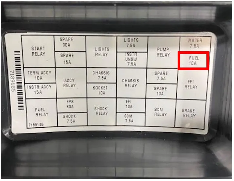
Underneath the dash, remove the fuse box cover. On the back of the fuse box, you will see a diagram showing a 10AMP fuse in the fuel spot. Switch this fuse out with a 20amp fuse.
- Step 12
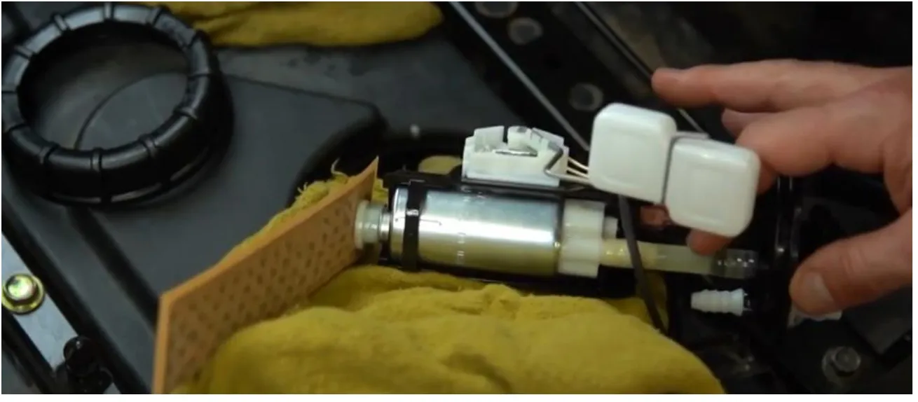
Test the fuel pump by turning on the key and listen for the pump to activate. Do this several times to prime the fuel system. Check for leaks. If there are no leaks, re-install the access cover and passenger seat.
Procedure
Clutching P43 270-280 Kits
- Clutching for 270-280 kits must be adjusted for an 8600-8800 RPM shift out.
- Running a 91-octane tune clutching must be adjusted for 8500 RPM shift out.
Procedure
MaptunerX / CodeShooter
Now that your Paragon turbocharger kit is install, you need to flash your ECU before starting the vehicle. Make sure the proper fuel is in your vehicle before starting it. If you have already contacted your sales representative and have a big turbo file, please follow the step-by-step MaptunerX or CodeShooter instructions found on our website.
Procedure
Launch Control (optional)
If Launch Control has been purchased as part of this kit, your clutching engagement RPMs MUST be raised to at least your chosen engagement. This kit has launch files for 2400, 2600, 2800, 3000, and 3200 RPMs.
Caution
Before initial startup, unplug the injector connectors and remove the oil drain tube from the turbocharger. Turn the car over 10seconds until you see oil coming from the drainpipe on the turbocharger. This will ensure the turbocharger is oiled before start up. All EVP turbochargers come pre-oiled this is another precaution step.
Need technical support?
Submit a ticket with your vehicle and what you're seeing, and our support team will get back to you.
