 BUY NOW, PAY LATER. Starting at 0% APR


READ THROUGH ALL INSTRUCTIONS PRIOR TO BEGINNING THIS INSTALLATION
Can-Am X3 Shift-Tek Essential Clutch Kit
Installation instructions for the X3 Shift-Tek Essential Clutch Kit on the Can-Am Maverick X3 (SKU 402FC0020-402FC0024). Parts, tools, and full procedure.
Before you start
| Shift-Tek Clutch Kit Part Numbers | EVP Tune | Engine Power Level | Use | Primary Spring | Weights | Secondary Spring | Helix |
|---|---|---|---|---|---|---|---|
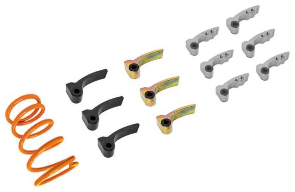
| B-180-W | 17-21 Stock | 160-190HP | Sand/Trail | Stock | 4 Gold | Stock | Stock |
| B-205-W | 17-21 Stages 1-3R, 2020 RR Stage 1 | 190-205HP | Sand/Trail | EVP Orange | 2 Black 4 Gold | Stock | Stock |
| B-225-W | 17-21 Stages 3RWI-5RWI, 2020 RR stages 2-3 | 205-225HP | Sand/Trail | EVP Orange | 3 Black 3 Gold | Stock | Stock |
| B-235-W | 2020 RR Stages 3R-3RWI | 215-235HP | Sand/Trail | EVP Orange | 4 Black 2 Gold | Stock | Stock |
| B-250-W | 2020 RR Stages 4RWI-X85 | 235-250HP | Sand/Trail | EVP Orange | 6 Black | Stock | Stock |
| B-ADJ-W | Any | 250-300HP | Sand/Trail | EVP Orange | 6 Adjustable | Stock | Stock |
Note
- FOR BASE 120hp MODELS, If you re-use stock secondary spring, keep it in HOLE 2.
- Cam arms must be installed in the correct location to maintain the balance of the clutch. Please note the instructions for the various stages below.
In the box
Parts and tools
Note
Clutch weights will change depending on what stage you purchase.
Required tools
- Clutch Service Tool Kit
- Screwdriver(s)
- T-25 Torx
- 8 mm socket
- Magnet
Procedure
Cam Arm Removal and Installation Without Removing Primary Clutch
- Step 1
Remove clutch cover and belt.
- Step 2
OEM cam arm removal, use a T25 Torx bit on one end of the pin and an 8mm socket on the other and remove the nut.
- Step 3
Remove the pin
- Step 4
Use a magnet to retrieve the cam arm – be careful to save the washers that are installed on both sides of the arm – these will be needed if you ever use the stock weights again. They are NOT needed for the installation of the EVP weights.
- Step 5
For removing the stock cam arms and installing the adjustable arms the clutch will have to be compressed slightly to slide the cam arms into place. See picture below on where to do this.
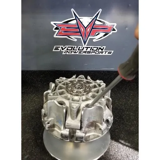
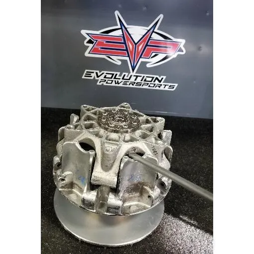
- Step 6
To install the new cam arms, slide an arm into the location where the previous arm was installed. Use a magnet to position the arm so the pin can be reinstalled. Reinstall nut onto pin.
Procedure
Removing the Primary Clutch & Using the Service Tool
- Step 1
Remove clutch cover and CVT drive belt.
- Step 2
Remove primary bolt using a 22mm socket. Remove primary clutch bolt.
- Step 3
Use a primary clutch removal bolt and remove the clutch, move to a clean workspace.
- Step 4
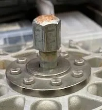
Place clutch puller bolt into the primary clutch, hand tighten until its 1 1/2" from the clutch housing.
 Note
Put anti-seize on the top of the bolt. This will help NOT damaging the head.
- Step 5
Place the service tool onto the primary, hand tighten (6) M6 Allen screws into the clutch basket. Hand tighten the service tool bolt into the clutch until it hits the head of the clutch puller bolt, which has anti-seize on the head. (Figure 1)
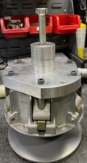
Fig. 1 - Step 6
With an impact and 24mm socket, tighten down the service tool bolt until you hear it pop. This is removing the basket of the clutch from the stationary sheave.
- Step 7
Remove the spider from the basket, keep all (6) rubber caps. (Figure 2)
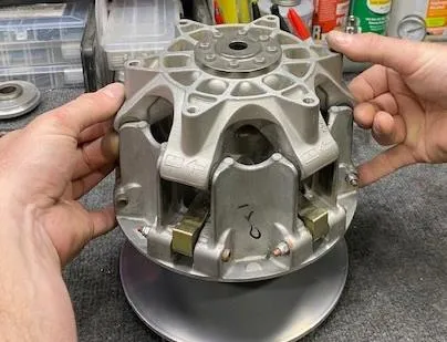
Fig. 2 - Step 8
Remove the basket from the stationary sheave, and place into a clutch compression tool.
- Step 9
With a sharpie, draw an alignment mark from the spring cap to the spider. This will ensure proper alignment when reassembling. (Figure 3)
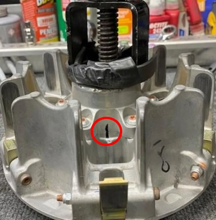
Fig. 3 - Step 10
With a T-30 Torx, loosen all (6) bolts securing the spring cap.
- Step 11
Loosen the clutch compression tool. Remove spring cap and primary spring.
- Step 12
Blow out the primary basket with compressed air. With green scotch brite pads, clean the inner surfaces of both sheaves. Wipe down with a clean rag and brake cleaner. (Figure 4)
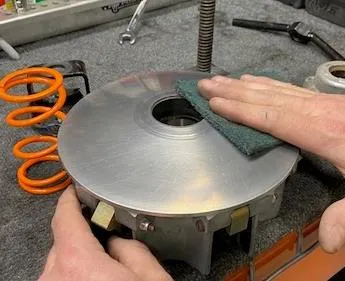
Fig. 4
Procedure
Removing and Installing Weights
- Step 1
With an 8mm socket and T-25 Torx, loosen one weight pin at a time.
- Step 2
Remove the weight pin, remove the weight. (Figure 5)
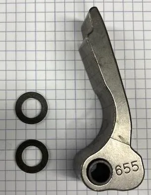
Fig. 5 NoteOEM weights have (2) bushings, keep these if you ever want to reuse the OEM weights. They are NOT needed for EVP weights.
- Step 3
Install the new EVP weight and reuse the OEM pin and Nylock nut. Tighten down till the pin is snug, we want the weights to move effortlessly.
- Step 4
Do step 1-3 for the rest of the weights.
Note
Primary clutches need to be perfectly aligned. If you place a gold weight in the clutch, across from it needs to be a gold weight. Same for black weights.
FOR EXAMPLE:
ST-2021RR 3R-91
- 3 Black, 3 Gold
- The EVP cam arms need to be staged as 1 black, 1 gold, 1 black, 1 gold, 1 black, 1 gold.
ST-2021RR 3R-93:
- 4 Black, 2 Gold
- The EVP cam arms need to be staged as 2 black, 1 gold, 2 black, 1 gold.
Procedure
Reassembling the Primary Clutch
- Step 1
Place the basket back into the clutch compression tool. Place the EVP Orange primary spring into the clutch and spring cap. Compress the spring cap and make sure the alignment marks line up. (Figure 6)
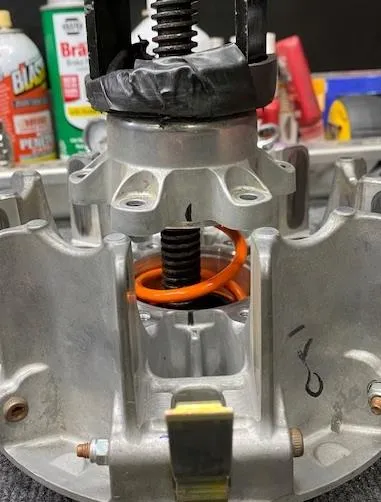
Fig. 6 - Step 2
Use Blue Loctite on (6) T-30 Torx securing the spring cover. Torque to 9Nm or 80 in-lb.
- Step 3
Remove the basket from the clutch compression tool, place basket onto stationary sheave.
- Step 4
Place the spider into the basket, make sure all rubber caps are installed before seating. (See figure 7).
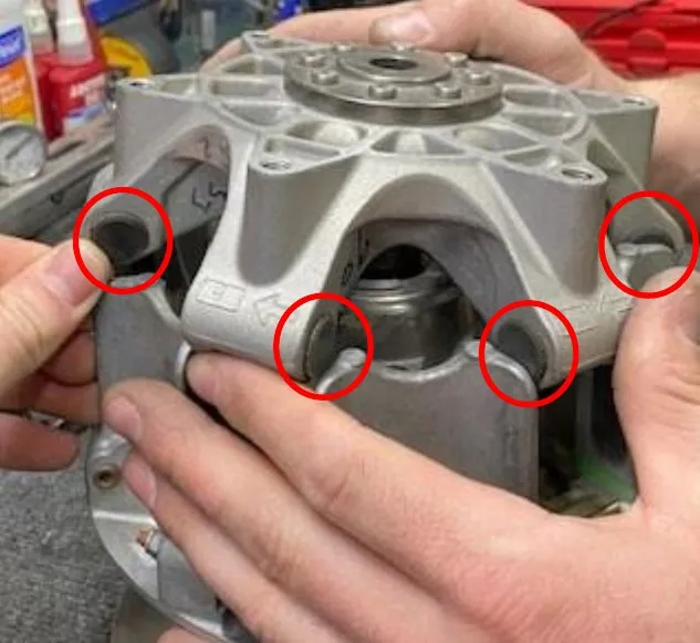
Fig. 7 - Step 5
Place the clutch puller bolt back into the primary clutch and tighten down with a 19mm wrench. This will press the basket back onto the stationary sheave. Remove bolt and install the primary clutch back onto the machine.
- Step 6
Torque the primary bolt (22mm) down 89 ft-lb. If you are reusing the OEM bolt, torque the primary down to 89 ft-lb and drive the car 100-200 yards and hit 5,000rpms. Retorque the primary bolt to 89 ft lb. Do this three times.
 Note
Can Am OEM primary bolts are made for one time use, we recommend our EVP XR Series primary clutch bolt. P/N 404FC0018
Setup
setup
B-180-W
- 4 gold weights
- The EVP cam arms need to be staged as 1 stock, 2 gold, 1 stock, 2 gold.
B-205-W
- 2 black, 4 gold
- The EVP cam arms need to be staged as 1 black, 2 gold, 1 black, 2 gold.
B-225-W:
- 3 black, 3 gold
- The EVP cam arms need to be staged as 1 black, 1 gold, 1 black, 1 gold 1 black, 1 gold.
B-235-W
- 4 black, 2 gold
- The EVP cam arms need to be staged as 1 gold, 2 black, 1 gold 2 black.
B-250-W
- 6 black
- The EVP cam arms will replace all the arms.
B-ADJ-W
- 6 Adjustable weights
- The EVP cam arms will replace all the arms.
Stock Turbo Tunes: Shift RPMS 7900-8100
Big Turbo Tunes: Shift RPMS 8000-8300
Emissions notice. This product is exempt from the emission standards and related requirements of 40 C.F.R. § 1051 as provided by 40 C.F.R. § 1051.620, and California law [e.g., vehicle code §§ 27156 and 38391]. This product is sold only for use in connection with EPA certified, purpose-built, nonroad vehicles used solely for closed course, nonroad competition/racing and not used for any recreational purpose or on public highways or right of ways maintained by and open to the public. This product is sold only in connection with machines that do not fall under state and/or federal noise or emission standards/regulations. Purchasers who/that purchase this product represent and warrant that the product is purchased only in connection with EPA-certified, emission-regulations-exempt and noise-regulations-exempt competition/racing vehicles as interpreted under applicable state and/or federal law.
Need technical support?
Submit a ticket with your vehicle and what you're seeing, and our support team will get back to you.
