 BUY NOW, PAY LATER. Starting at 0% APR


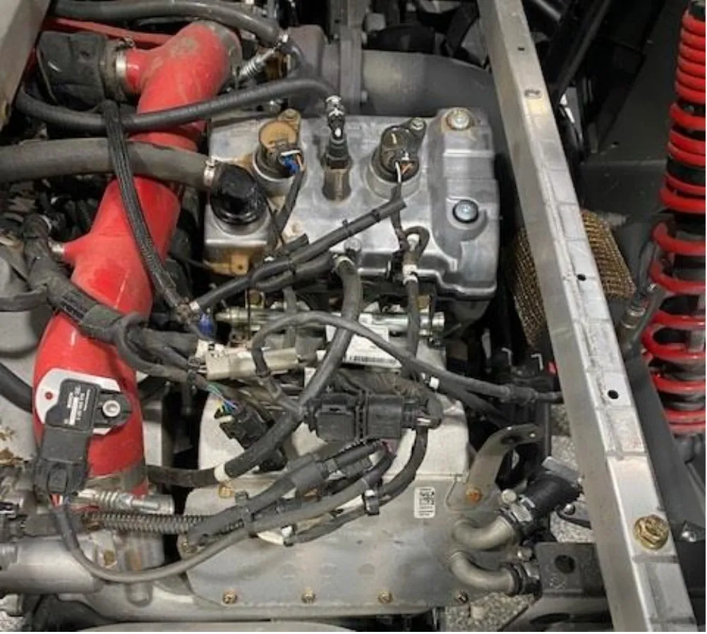
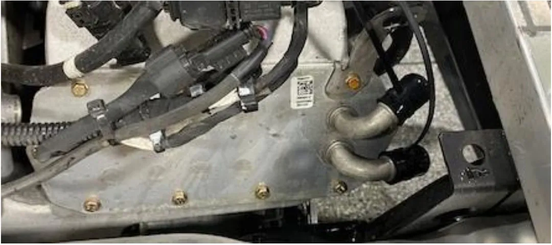
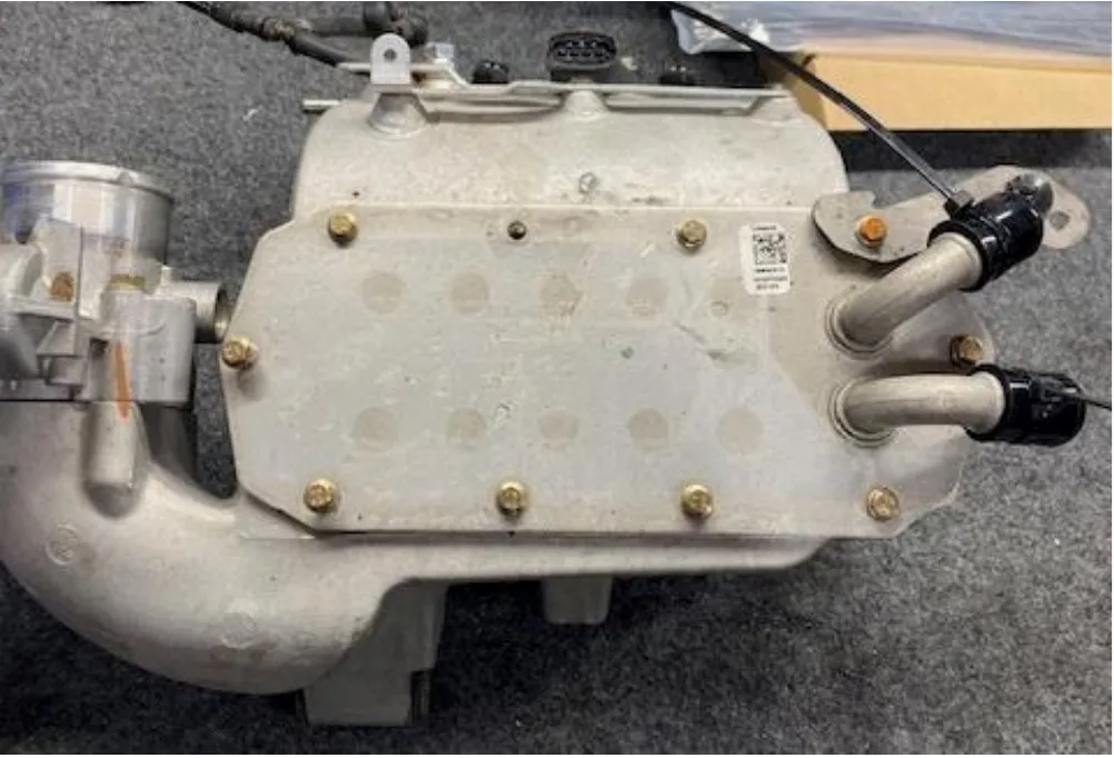
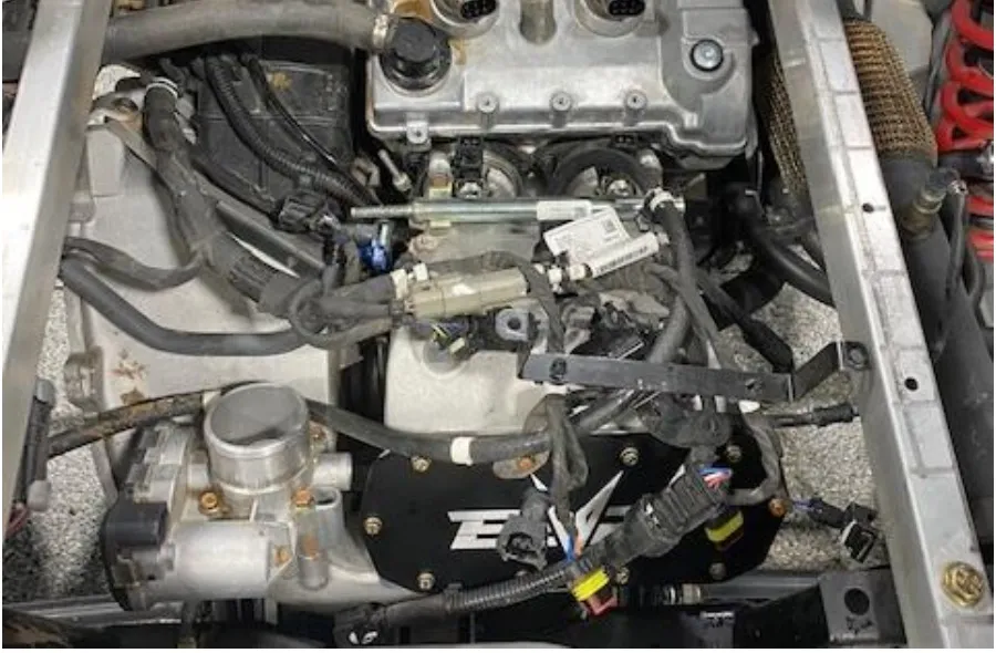
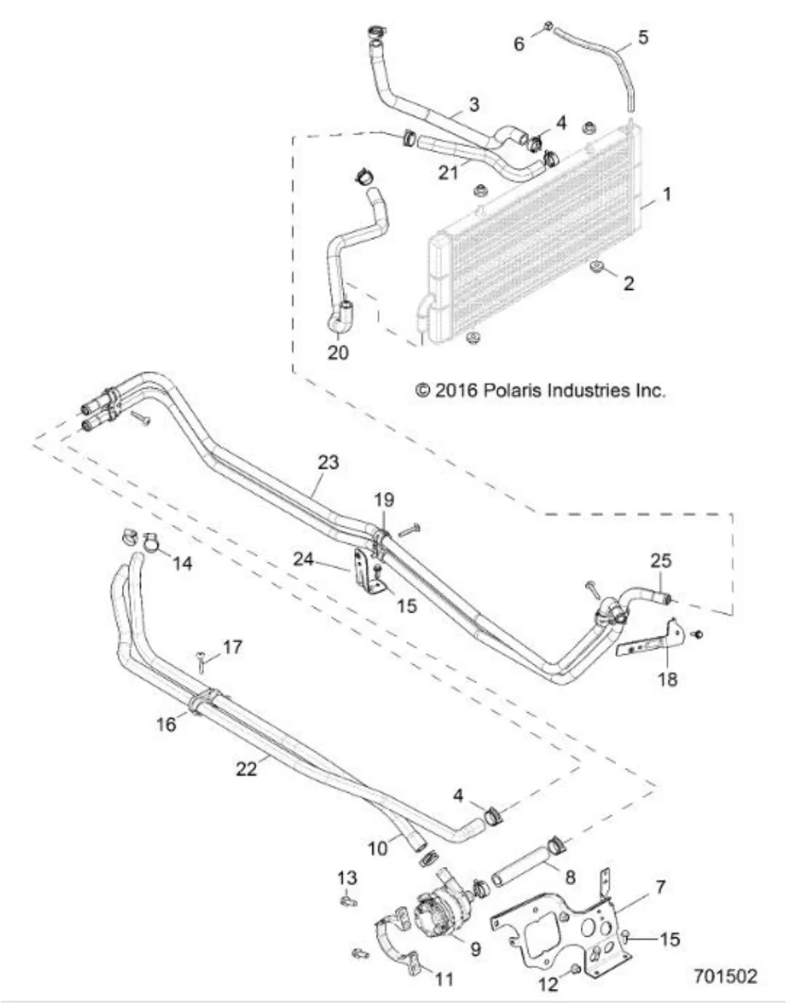
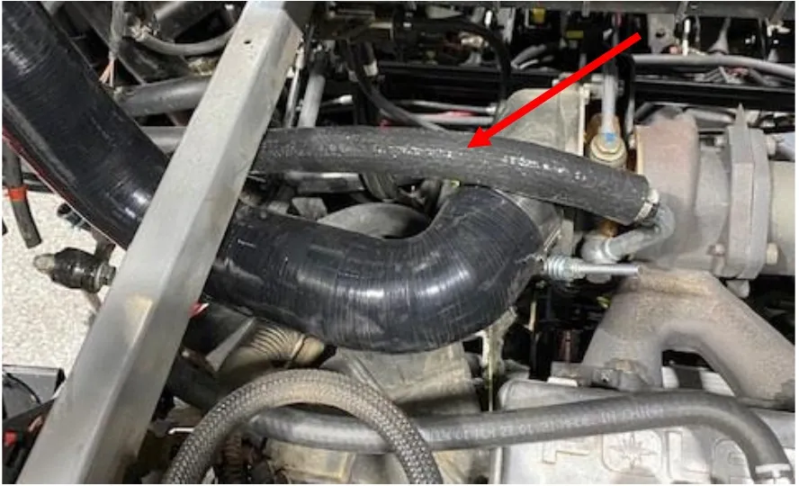
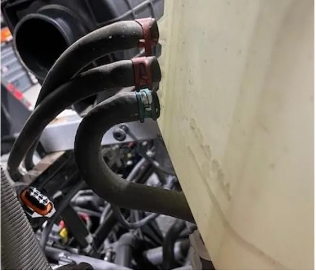
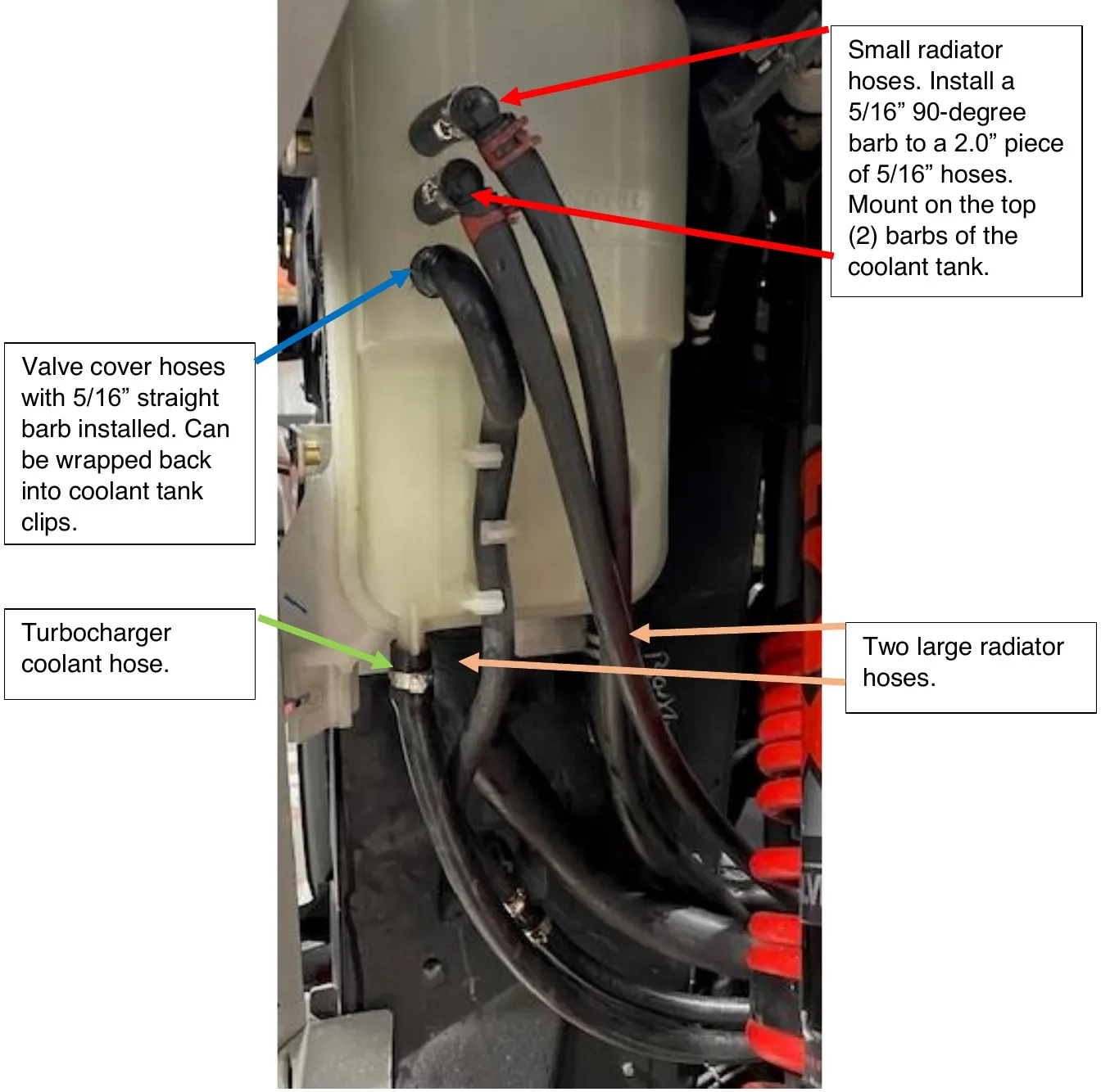
Below is the diagram for all hoses mounted on the coolant tank.
Polaris Pro XP & Turbo R Air to Air Intercooler Kit
Installation instructions for the Pro XP & Turbo R Air to Air Intercooler Kit on the Polaris Pro XP (RZR) (SKU 100FP0189). Parts, tools, and full procedure.
In the box
Parts and tools
Included parts
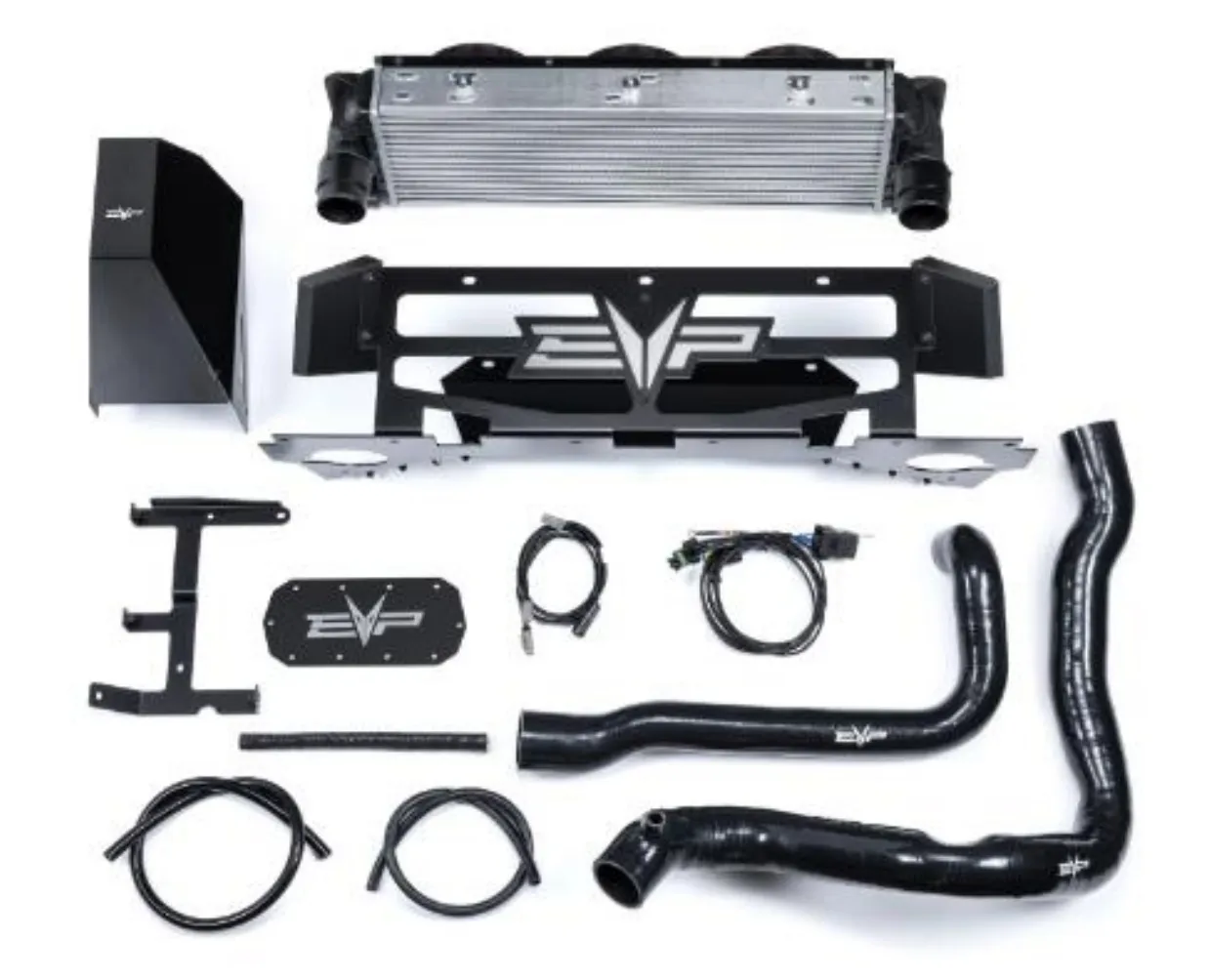
- 1Pro XP & Turbo R Air to Air Intercooler Assembly
- 1P43/P50 Charge Tube Kit, Black
- 1Triple Fan Intercooler Install Kit
- 1Coolant Tank Relocation Kit
- 1Triple Fan Install Kit
Required tools
- Screw Driver
- Metric Sockets
- Clamps
- Torx Sockets
- 3” Whole saw or air Dremel
Procedure
Installation
- Step 1
Make sure the vehicle is cold. You can remove the bed by removing (4) T-40 screws.
- Step 2
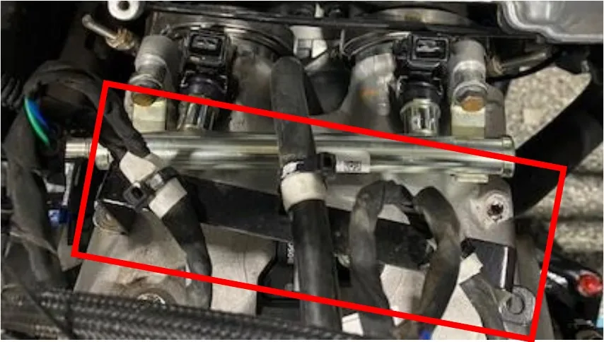
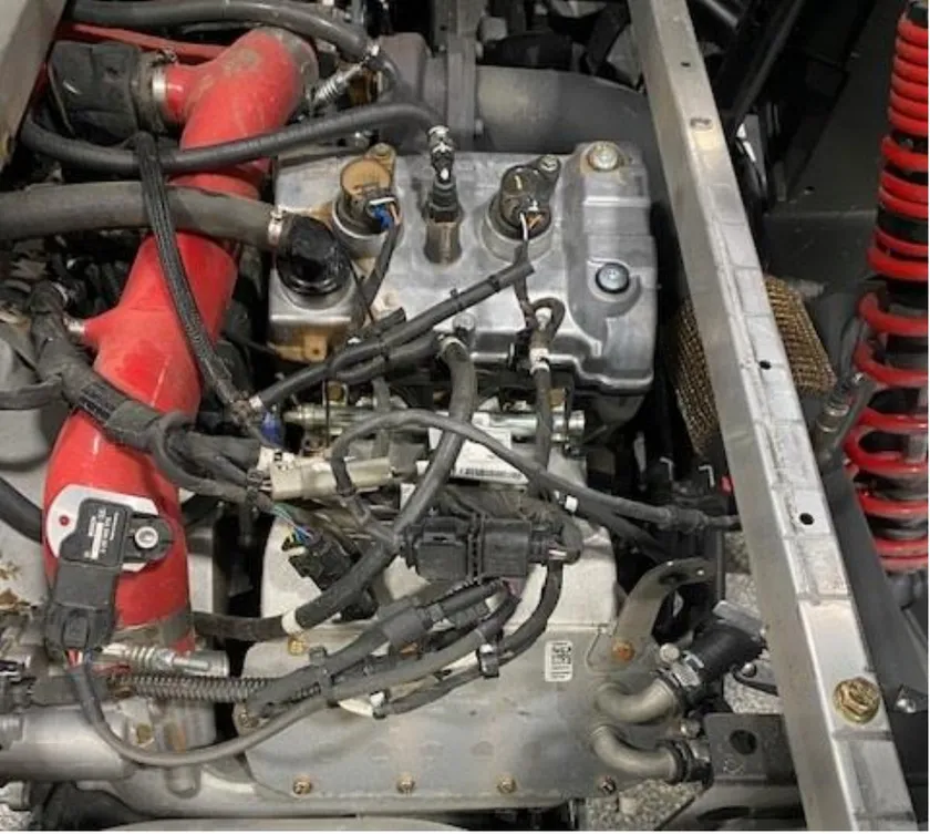
Locate the plenum. Spray the plenum boots with brake cleaner. Remove the charge tube, unplug both map sensors, unplug the coils, remove the fuel line.
- Step 3
You may need to remove the plenum from the vehicle to remove the intercooler. Sometimes you can sneak the intercooler around the frame, but you may ruin the intercooler fins in the process. For these instructions we removed the plenum.
- Step 4
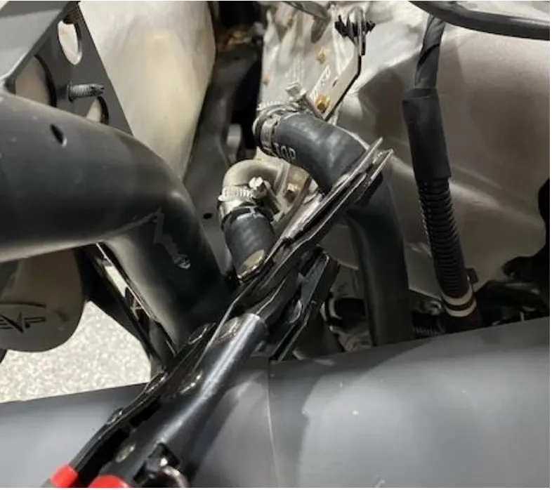
Pinch both coolant lines off, going to the intercooler. Remove the hoses from the intercooler. Plug the intercooler for less mess.
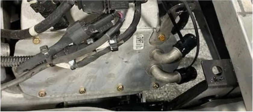
- Step 5
Remove the 13mm bolt on bottom of the plenum/transmission mount.
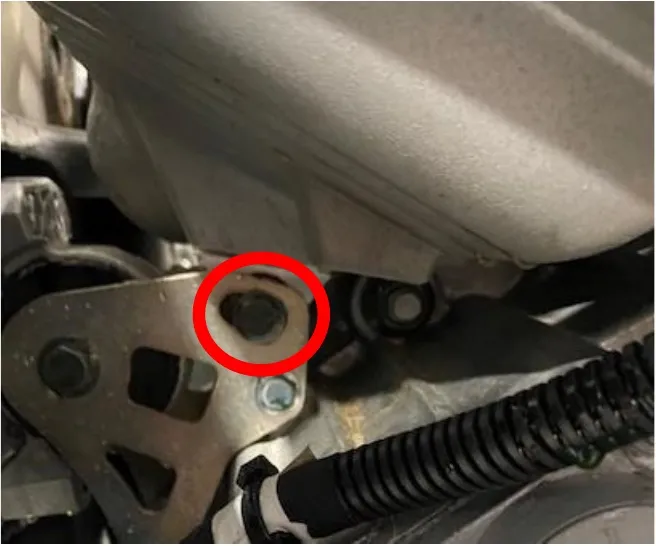
- Step 6
Remove the intake plenum V-band clamps on the runners, remove the plenum from vehicle.
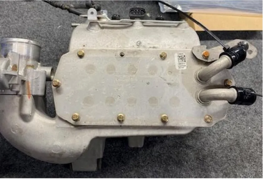
- Step 7
With a 8mm socket, remove (10) screws holding the intercooler into the plenum. Remove the plenum and look for oil/coolant in the bottom of your plenum. Clean any debris that is found in the plenum, the OEM intercoolers are prone to leaking.
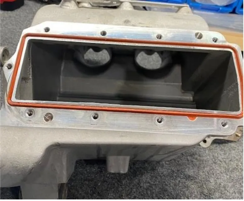
- Step 8
Install the supplied intercooler block off plate, re-use OEM hardware and bracket.
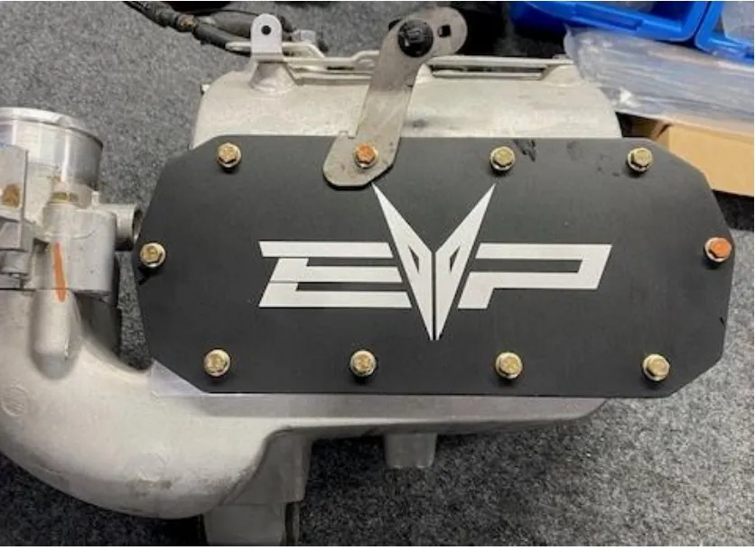
- Step 9
Reinstall the plenum into the vehicle. Reconnect everything except the charge tube.
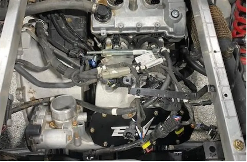
- Step 10
This step is totally up to the customer. You can install the supplied 5/8” 90-degree hose barb and tie the coolant hoses together, if you think you may go back to the OEM intercooler at some point. Or you can remove all the soft/hard lines going up to the radiator and remove the radiator.
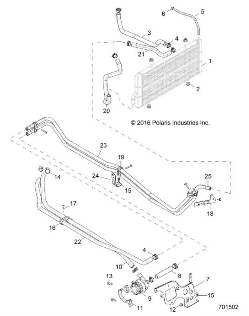
Procedure
Intercooler Installation
- Step 1
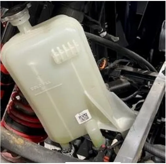
Remove the coolant tank reservoir cap. Place a catch pan underneath the coolant tank and remove both hoses to drain.
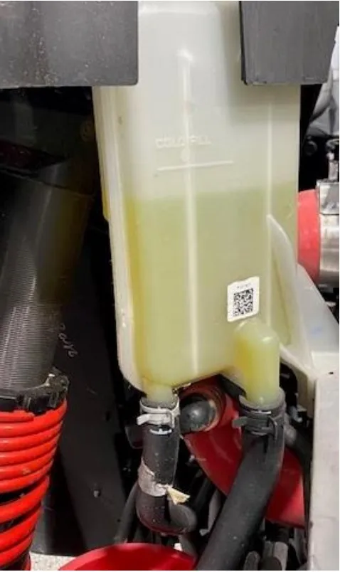
- Step 2
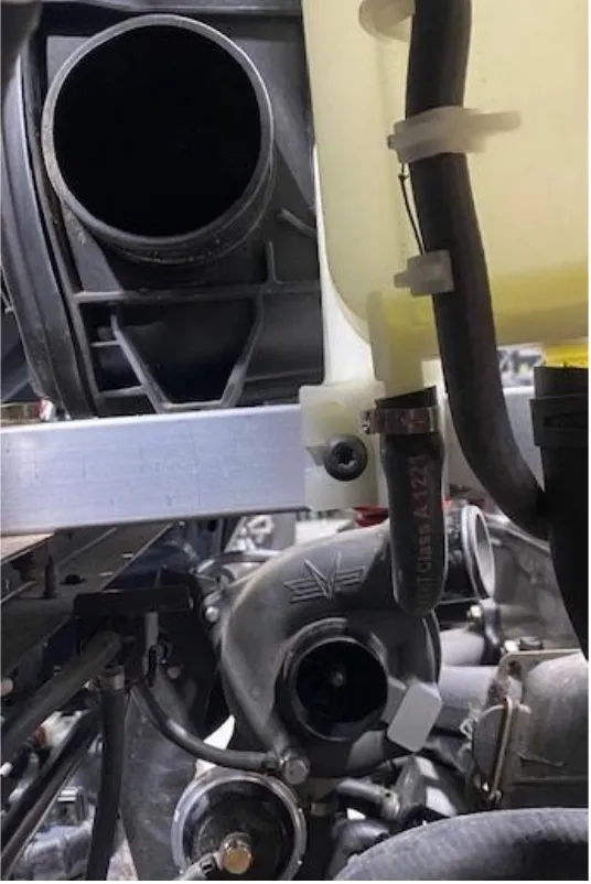
Remove the V-flow form the airbox to turbocharger.
- Step 3
Remove the coolant tank reservoir from the upper plastic clip and bed frame rail. One T-30 screw.
- Step 4
Remove the (3) hoses from the rear of the coolant reservoir.
- Step 5
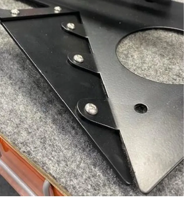
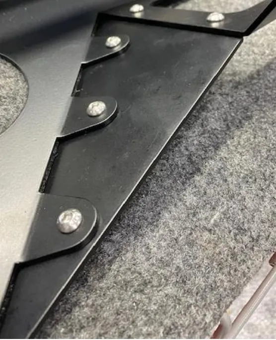
Locate the intercooler bracket. Unwrap the EVP backer plate (which can be powder coated) and the (2) supports. Install the supports using supplied (10) M6-16mm screws.
- Step 6
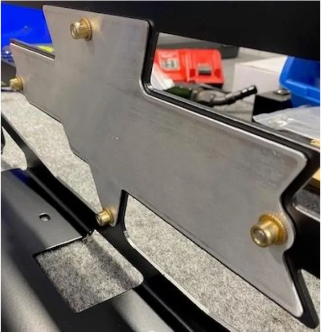
Install the EVP backer plate using (4) M6-16mm screws.
- Step 7
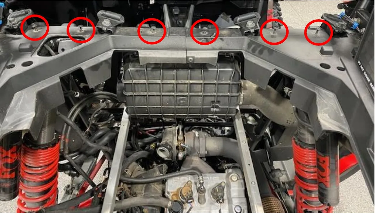
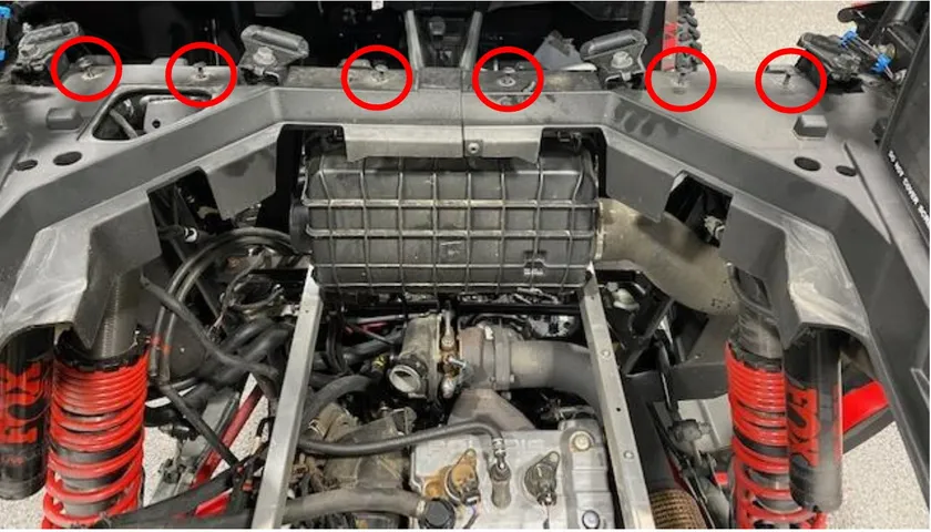
On the back of the vehicle, remove the (6) T40 screws holding the plastic on around the seat belts.
- Step 8
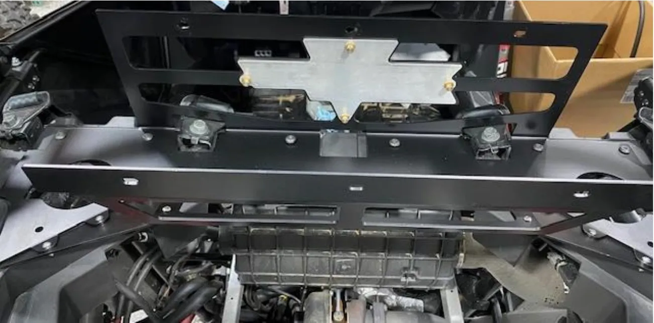
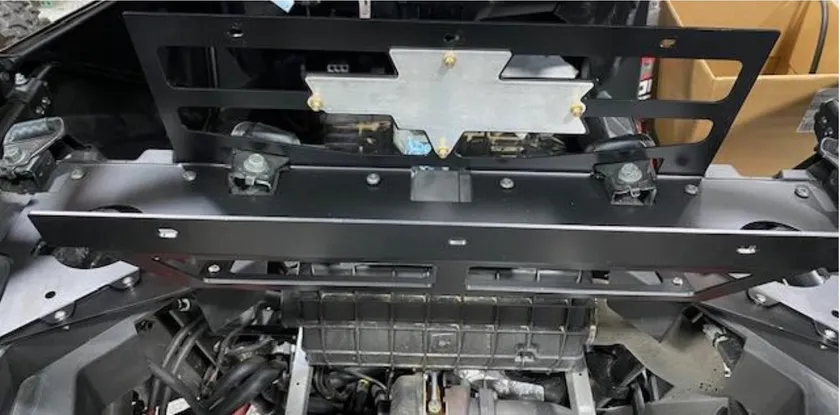
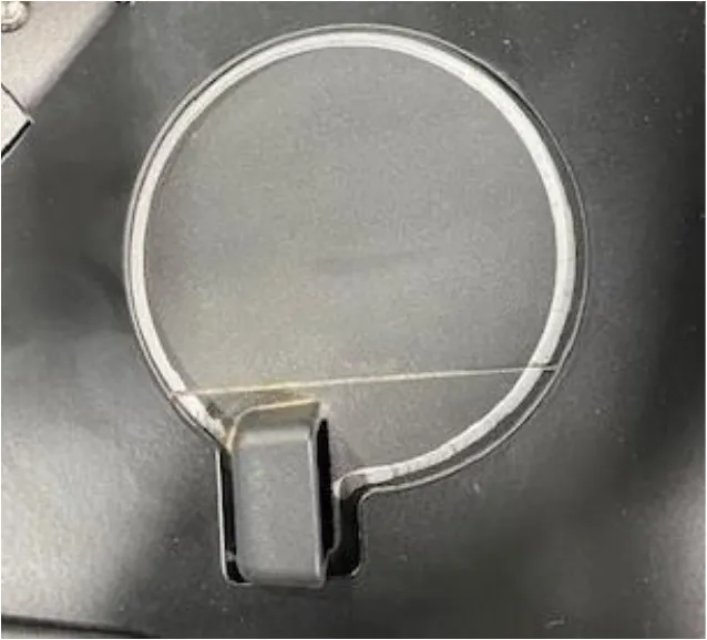
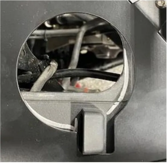
Install the intercooler mount onto the car. With the mount centered on the car, outline the (2) charge tube holes with a silver sharpie.
- Step 9
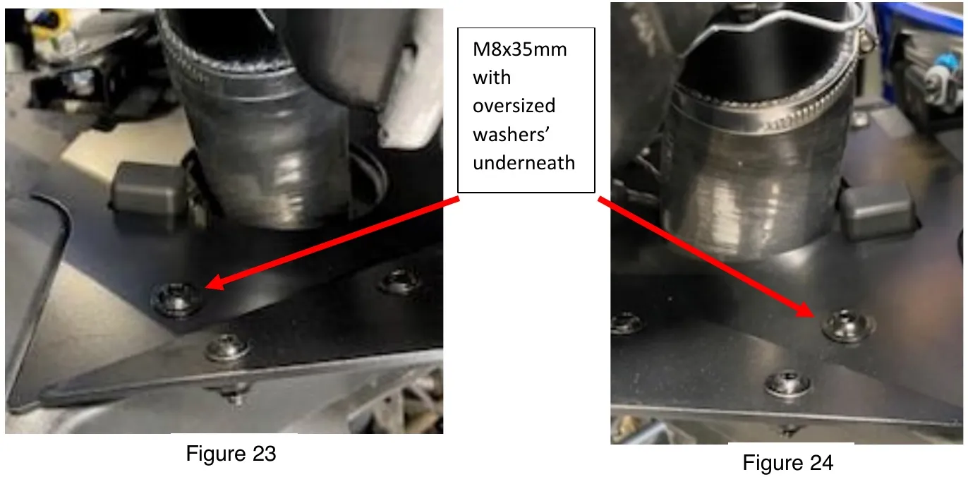
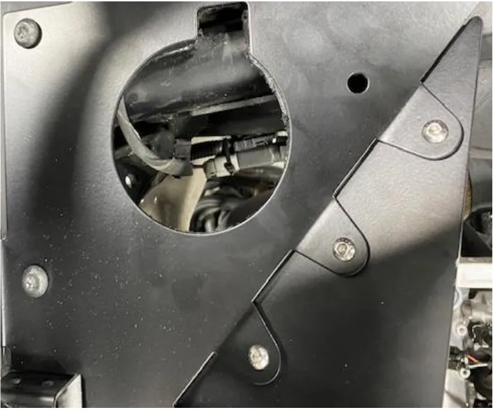
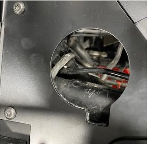
Remove the bracket and cut the holes out with air Dremel or 3.50” hole saw and drill. Once cut, sand the edges down and use a small heat source flame to smooth the edges. Reinstall the intercooler bracket onto the car, reuse the OEM hardware. One the back of the mount you will need to use supplied M8-35mm screws with oversized washers for each side.
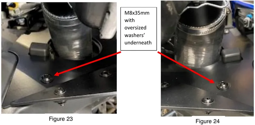
M8x35mm with oversized washers’ underneath - Step 10
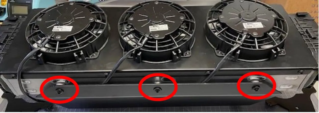
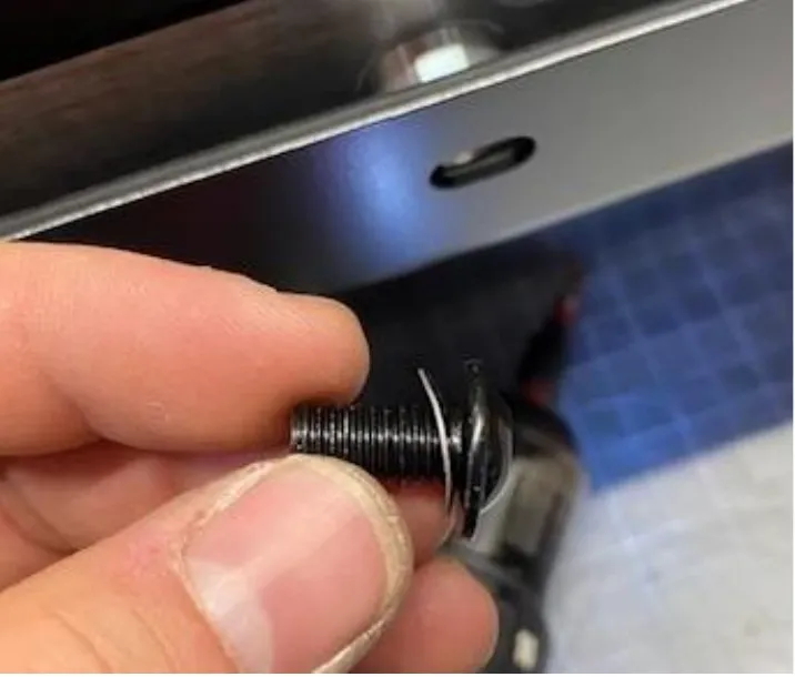
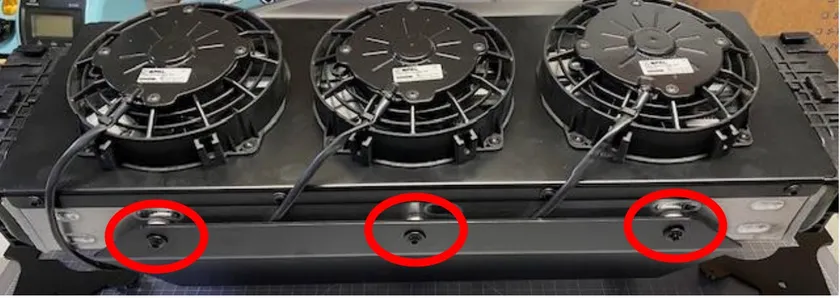
Install the intercooler onto the mount. Use supplied M8-16mm flanged screws with spring washers. A total of (6). Make sure the fan harnesses go inside the mount. (photo taken on work bench).
- Step 11
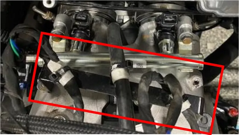
located on the plenum is a Black “C” bracket. Remove the (2) 8mm screws and engine harness zip ties. This will not be used.
- Step 12
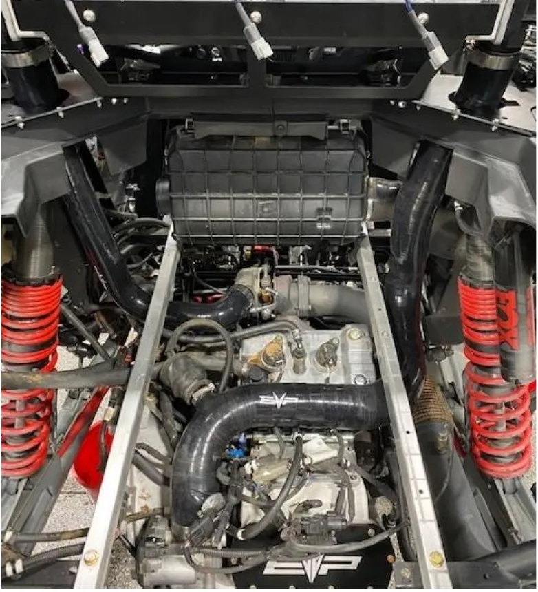
Install the charge tube going from the throttle body to intercooler. The tube will go underneath the bed frame rail.
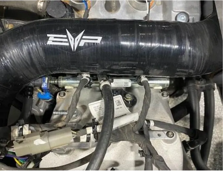
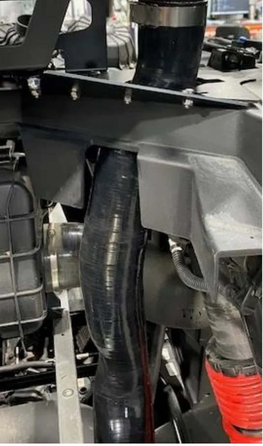
- Step 13
Install the other “L” shaped charge tube between the turbocharger and intercooler.
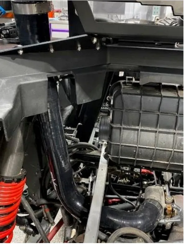
- Step 14
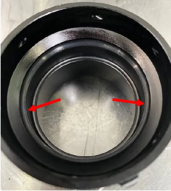
Install the O-rings into the billet charge tube connectors. Apply dielectric grease to the O-rings. The O-rings are directional, install as shown below.
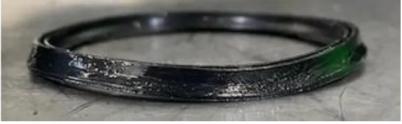
- Step 15
Install the billet connectors to the charge tubes going into the intercooler. You may need to apply dielectric grease to the outside of the billet adaptor. Use supplied T-bolt clamps to secure the charge tubes to adaptors.
- Step 16
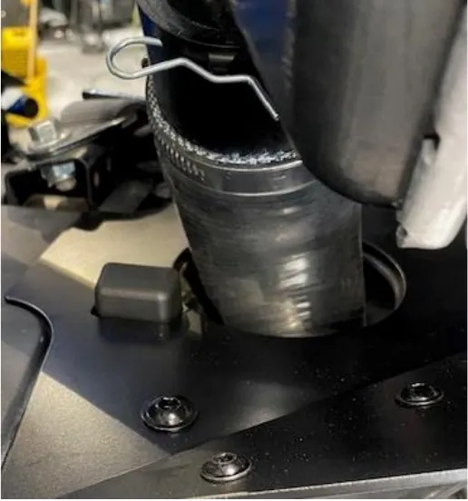
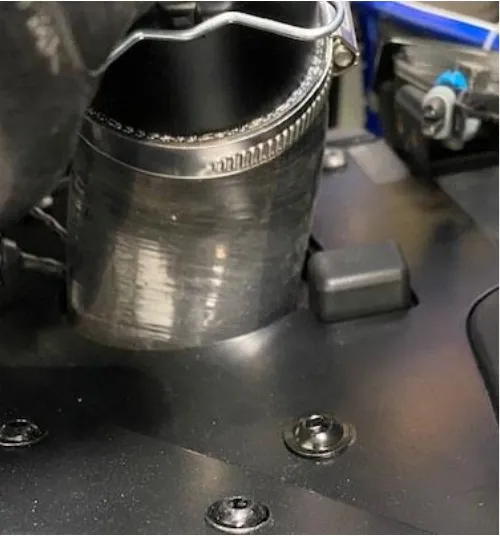
Install the billet connectors to the intercooler. Use (3) cotter pins per each side.
- Step 17
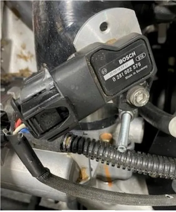
Install map sensor adaptor plate to the charge tube connected to the throttle body. Use supplied pinch clamp to fasten down. Install the map sensor and secure with M6x12mm screw.
- Step 18
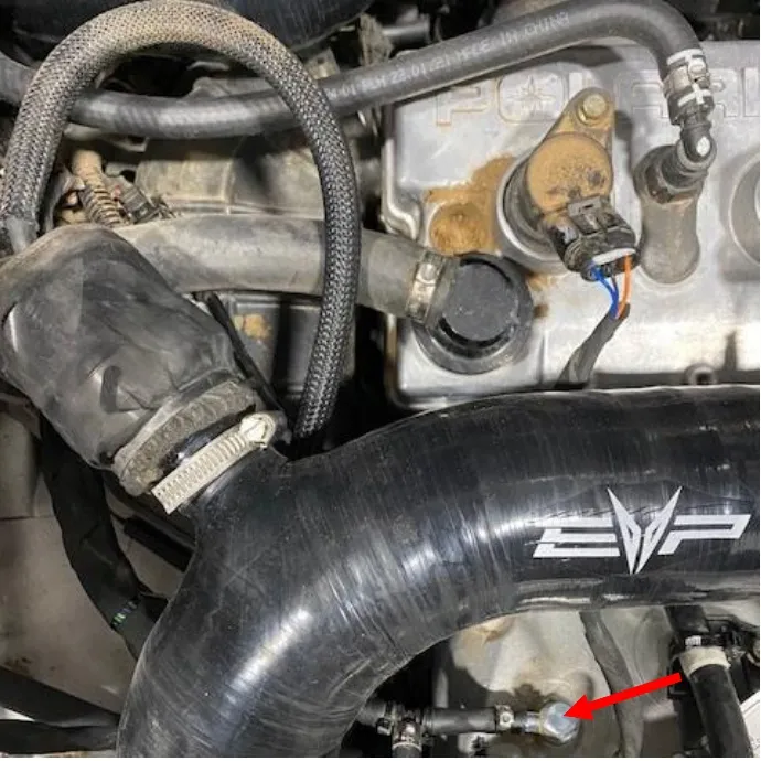
Install the BOV or BOV plug into the charge tube. If installing a BOV install the pre filter onto the BOV. Secure it with a supplied zip tie. Install the BOV into the charge tube and secure it with a 25-40mm worm drive. Route the vacuum line back to the plenum barb.
- Step 19
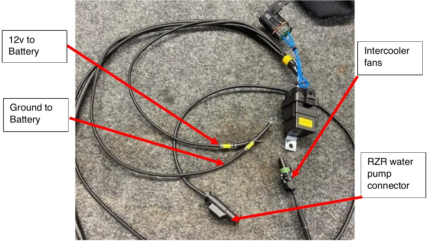
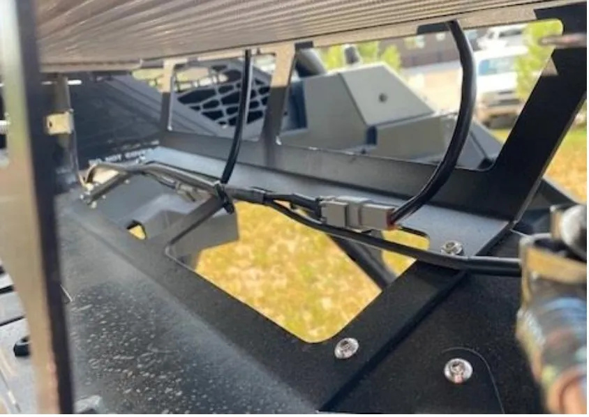
Intercooler wire harness below.
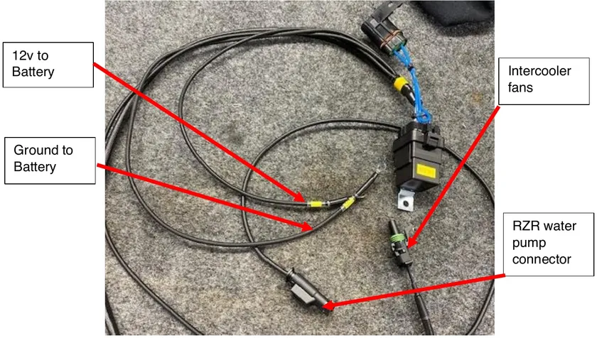
12v to Battery. Ground to Battery. Intercooler fans. RZR water pump connector. - Step 20
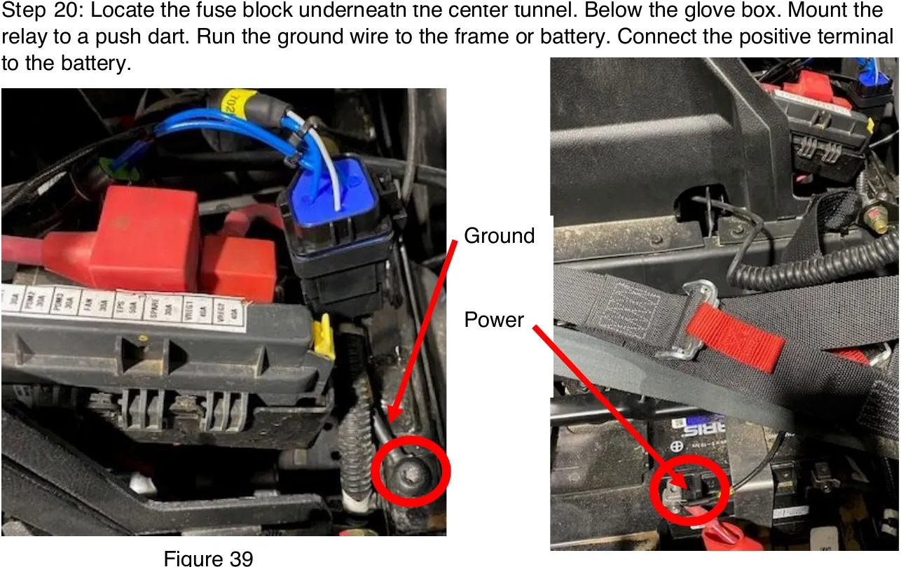
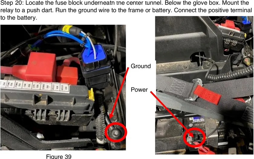
Locate the fuse block underneath the center tunnel. Below the glove box. Mount the relay to a push dart. Run the ground wire to the frame or battery. Connect the positive terminal to the battery.
Ground. Power. - Step 21
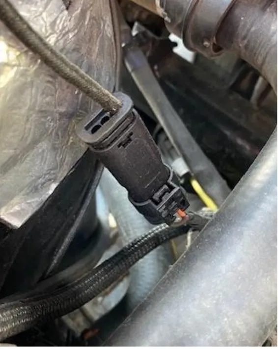
Run the other two pigtails through the firewall and into the engine. Remove the water pump connector from the water pump and connect the OEM harness into the intercooler harness. This is located directly underneath the turbocharger.
- Step 22
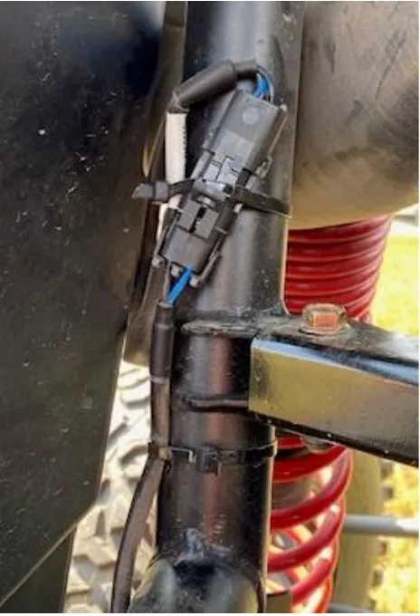
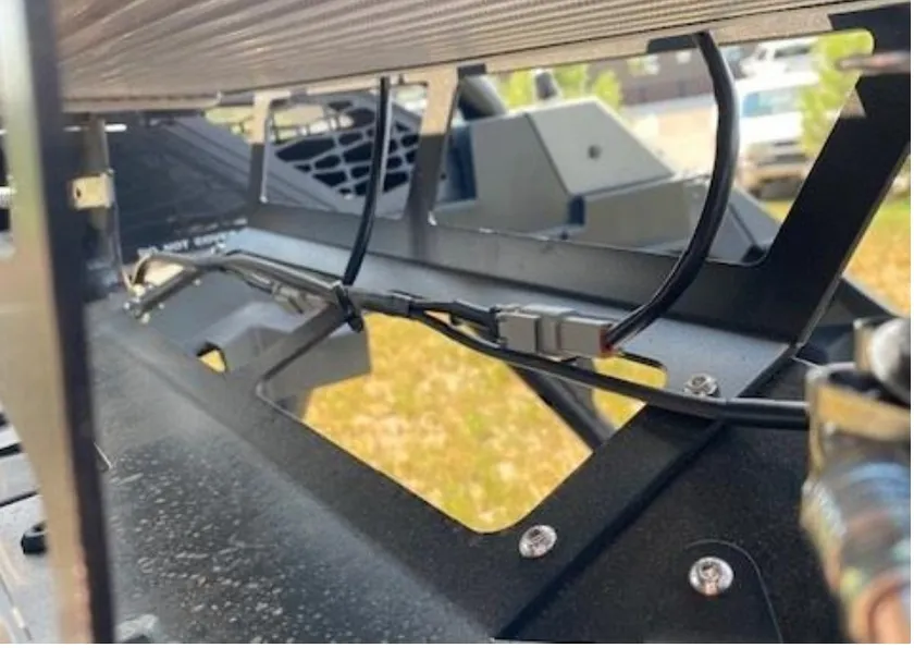
Run the fan harness pigtail behind the passenger seat, zip tie it to the frame rail. Plug in the triple fan harness and route it up to the intercooler. Plug in the fans.
- Step 23
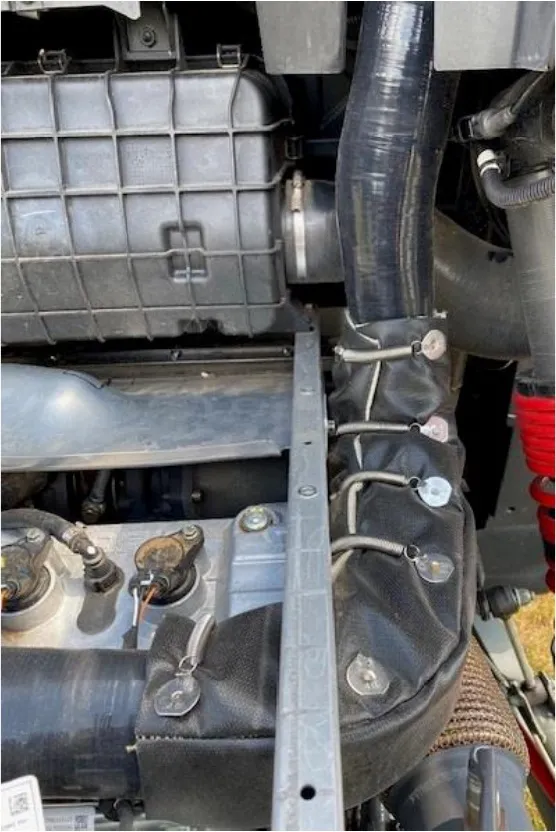
Install the heat blanket onto the charge tube above the exhaust downpipe.
- Step 24
Zip tie any excess wires underneath the center tunnel, keep wires away from any heat source.
Procedure
Coolant Reservoir Relocation
- Step 1
Behind the driver’s seat (left rear passenger if 4 seater) will be the ECU. Remove the (4) T-15 screws and let the ECU rest.
- Step 2
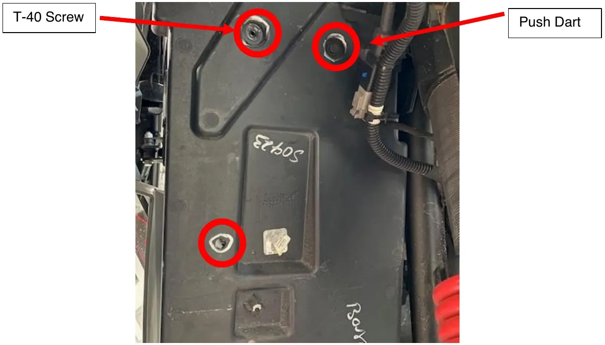
On the backside of the firewall, you will use these (3) OEM holes. Remove the upper left T-40 screw and the upper right push dart.
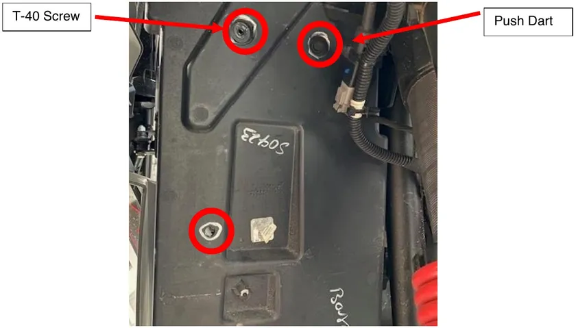
T-40 Screw. Push Dart. 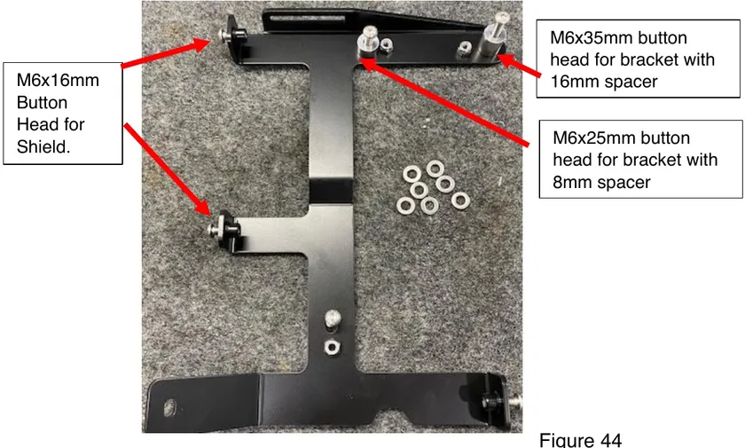
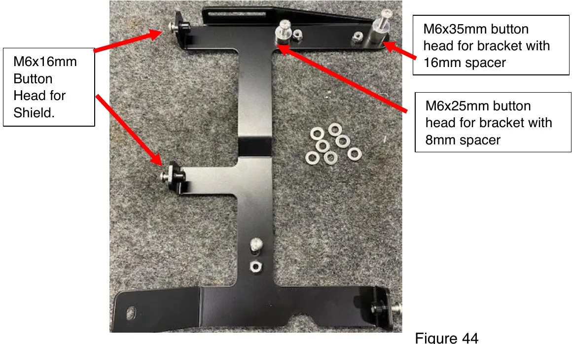
M6x16mm Button Head for Shield. M6x35mm button head for bracket with 16mm spacer. M6x25mm button head for bracket with 8mm spacer. - Step 3
Mount the bracket to the firewall using the correct hardware, spacers between the bracket and firewall, washers and nylock nuts. You can reuse the T-40 screw if you don’t want to remove the Nutzert.
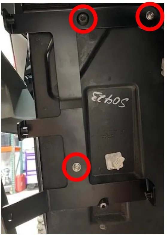
- Step 4
Install the 12” piece of fire sleeve onto the 36” of 3/8” water line. Connect the line from the turbocharger “J” fitting to the coolant tank (diagram below). Install (2) 22mm pinch clamps.

- Step 5
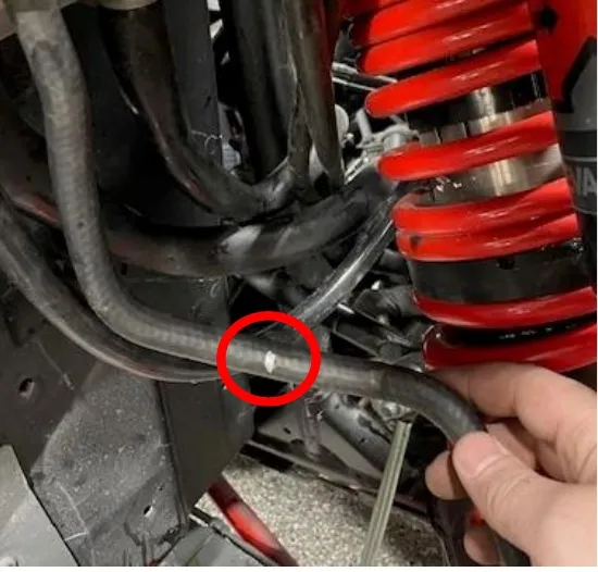
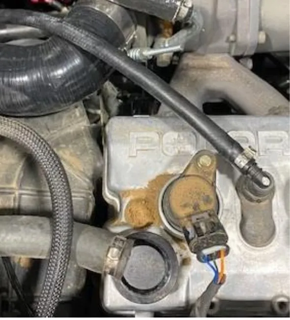
Remove the pinch clamp and hose from the valve cover. Keep the fitting attached to the valve cover. In the middle of that hose you fill find a straight 6” piece. Cut in the middle and disregard. You will reuse the pre-bent part.
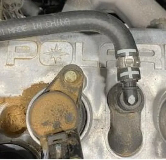
- Step 6
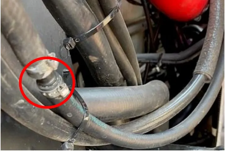
Install 32” of 5/16” hose to the valve cover fitting. Install a 5/16” straight barb to join the pre bent hose. Use (3) 15.7mm pinch clamps to fasten down.
- Step 7
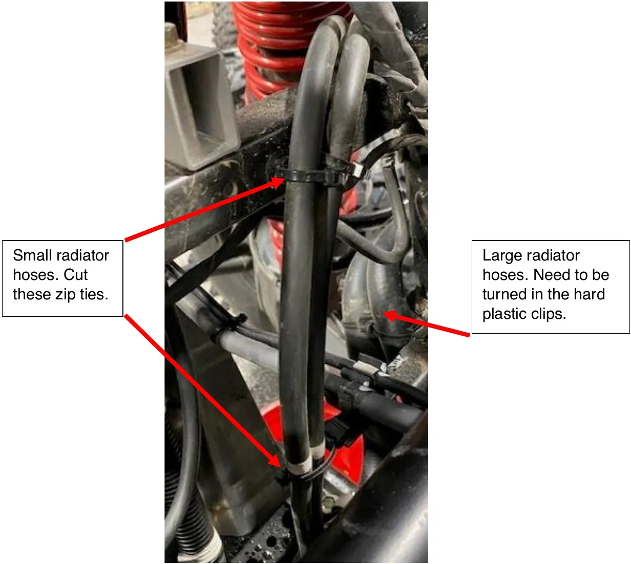
On the firewall frame you will locate (2) small radiator hoses. Cut the zip ties and feed them behind the drivers side firewall. You will also need to rotate the larger hoses in the hard plastic clamps located below.
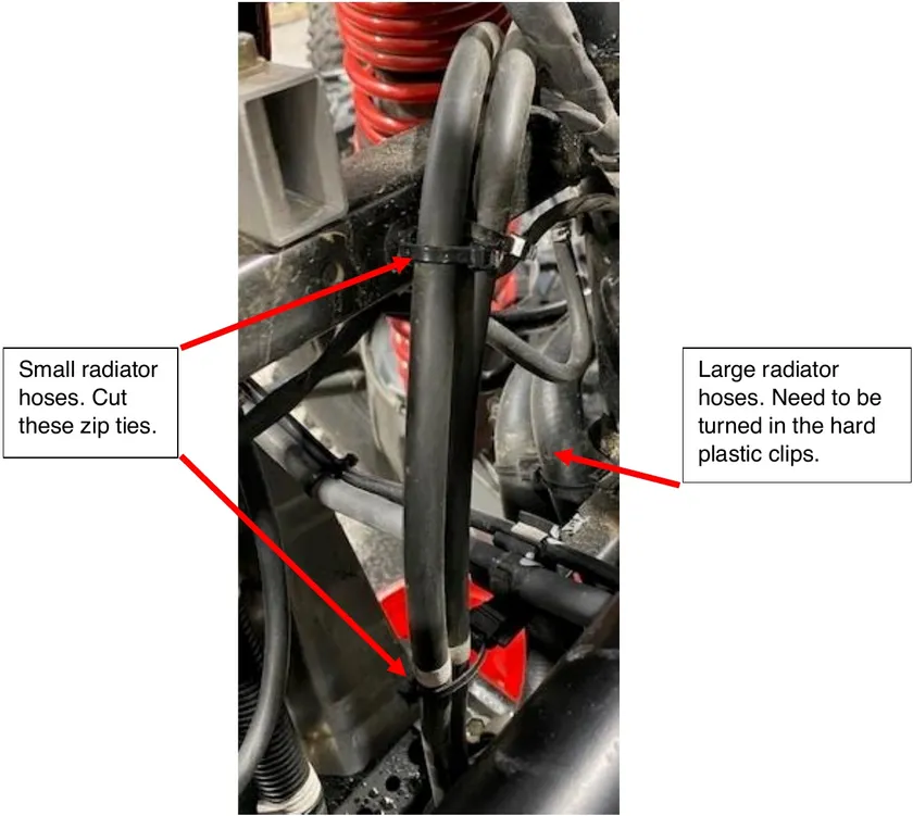
Small radiator hoses. Cut these zip ties. Large radiator hoses. Need to be turned in the hard plastic clips.
- Step 8
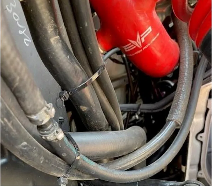
Zip tie the coolant hoses together.
- Step 9
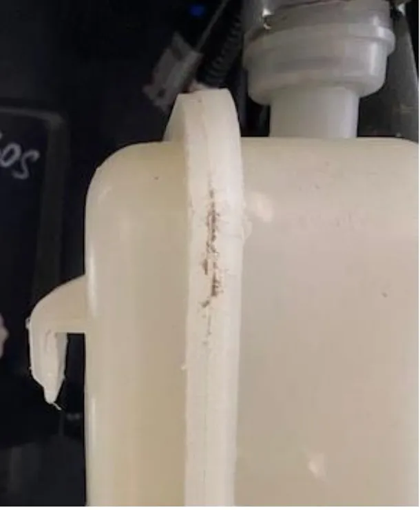
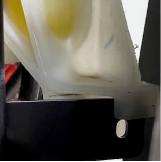
Install the coolant tank onto the bracket. The top “L” bracket will slide on top and the bottom will go around the lower leg of the bracket.
- Step 10
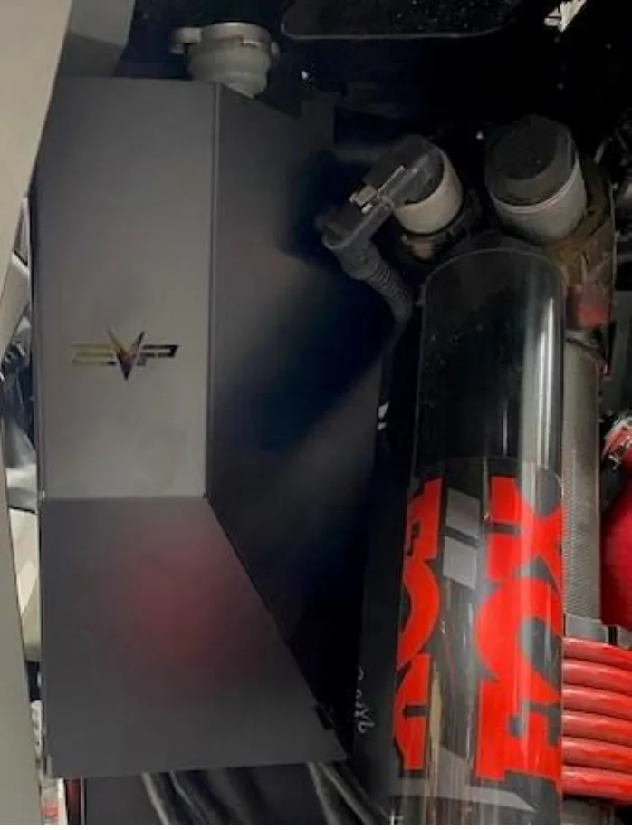
Fill your coolant tank up. Install the coolant tank sheild using suppllied M6x16mm button head screws with washers. You may need to unplug your shock for installation, reconnect when done.
- Step 11
Reinstall the V-flow and start the vehicle. Look for any coolant leaks. Make sure your fans are pulling air and NOT pushing air. Reinstall the rest of your vehicle.
Emissions notice. This product is exempt from the emission standards and related requirements of 40 C.F.R. § 1051 as provided by 40 C.F.R. § 1051.620, and California law [e.g., vehicle code §§ 27156 and 38391]. This product is sold only for use in connection with EPA certified, purpose-built, nonroad vehicles used solely for closed course, nonroad competition/racing and not used for any recreational purpose or on public highways or right of ways maintained by and open to the public. This product is sold only in connection with machines that do not fall under state and/or federal noise or emission standards/regulations. Purchasers who/that purchase this product represent and warrant that the product is purchased only in connection with EPA-certified, emission-regulations-exempt and noise-regulations-exempt competition/racing vehicles as interpreted under applicable state and/or federal law.
Need technical support?
Submit a ticket with your vehicle and what you're seeing, and our support team will get back to you.
