 BUY NOW, PAY LATER. Starting at 0% APR


A benefit to Code Shooter is the device reads right off your vehicles ECU. No additional hardware or modules are needed for reading boost with Code Shooter. Since the vehicle already reads boost off the Map sensor(s) in the plenum, with code shooter and your mobile device you can read live data coming from your vehicles ECU. Make sure your Code Shooter is plugged into the diagnostic port and paired with your mobile device.
Polaris Code Shooter with AFR, Belt Temp, & Boost for RZR Pro XP
Tuning & programming for the Code Shooter with AFR, Belt Temp, & Boost for RZR Pro XP on the Polaris Pro XP (RZR). Parts, tools, and full procedure.
In the box
Parts and tools
Included parts
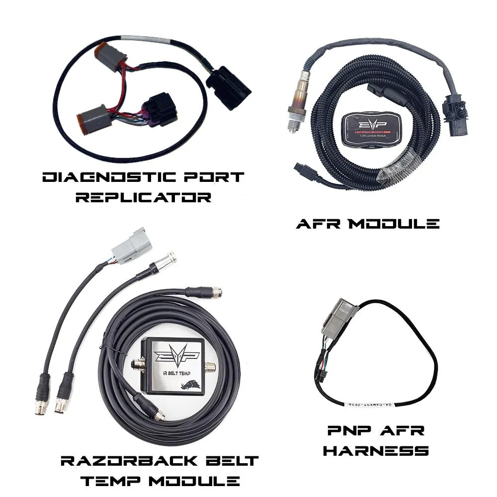
- 1AFR Module with Hardware
- 1Belt Temp Module with Hardware
- 1Polaris Diagnostic Port Replicator
- 1Can Am to Belt Temp Cable
- 1Code Shooter to RJ45 Cable
- 1Can Am to CAN Lambda Cable
Required tools
- Unibit (Step Bit) 1 1/4"
- 1/2" Drill Bit
- Push Dart Tool
- T-40 Torx Socket
- Sider Cutters
- Welder (02 Bung)
- Loctite/ Anti-Seize/ Silicone
- Velcro
- Rubber Gromet(s) (1-1/4”)
- Zip Ties
Note
The EVP Code Shooter App allows you to display live data of Air/Fuel Ratio, Belt Temperature and Boost on your mobile device. Optionally, you can pick and choose to purchase these modules for Air/Fuel Ratio and Belt Temperature. Boost is measured of the Map sensor and your plenum will always have a Map sensor(s). These instructions will show you how to locate your OBD port, install Code Shooter, AFR module, and Belt Temperature module. If you have not purchased all the modules you can skip through the instructions to the correct module you purchased.
Caution
We recommend mounting these modules in a clean, water resistant area. We installed these modules in a 2 seat RZR Pro XP and mounted the modules in the glove box. The customer can decide where they want to mount the modules whether its in the glove box or an accessory bag. These modules are NOT waterproof.
Procedure
Instructions for Boost:
Procedure
Instructions for AFR Module
- Step 1
Remove both passenger and driver captain’s chairs.
- Step 2
Remove the rear firewall access panel to the turbo.
- Step 3
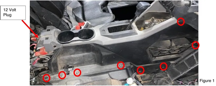
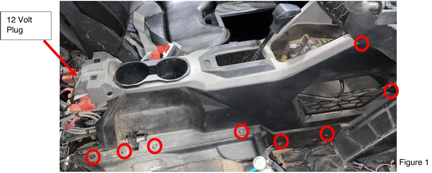
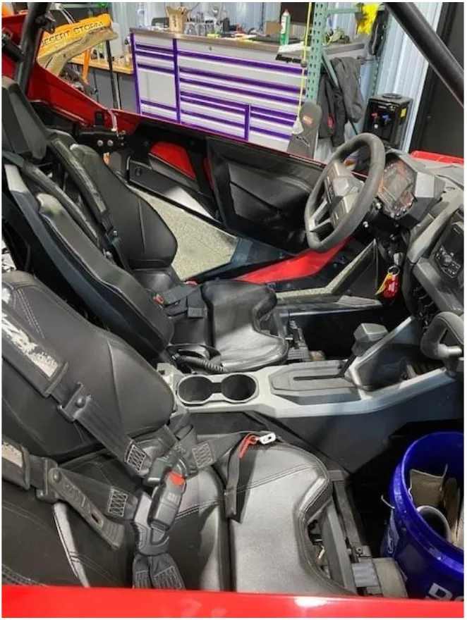
Remove the center console passenger side panel by removing (2) push darts and (8) T-40 Torx. Push the shifter rubber boot down into the center console. On the rear of the center console there is a 12 Volt plug, disconnect the Positive and Ground wire off. These wires are very short, and we need to lift the silver part of the center console away from the side panel. (Figure 1)
- Step 4
Remove the passenger side panel from the center console. Pull up on the silver trim, and with a small flat blade screwdriver disconnect the clips from the side panel, start in the rear and work your way towards the front of the vehicle. Let the side panel lay on the passenger floorboard.
- Step 5
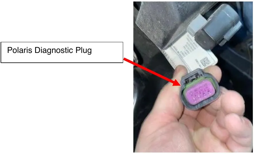
Underneath the steering column, you will locate the Diagnostic port. The Diagnostic port will be an 8-pin port with a purple internal clip. (Figure 2)
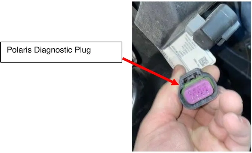
Figure 2 - Step 6
Locate the glove box, we will need to drill a 1 1/4" hole. To keep the wires and harness’s hidden, we drilled our hole in the already existing hole in glove box. Remove the OEM rubber gromet and drill from the bottom up. (See figures 3-4)
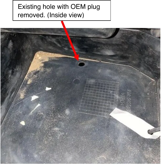
Figure 3 Existing hole with OEM plug removed. (Inside view) 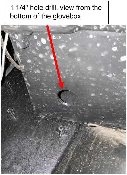
Figure 4 1 1/4" hole drill, view from the bottom of the glovebox. - Step 7
Grab the supplied diagnostic triple Indy wiring harness, feed the Polaris male (2 ft end) from the glove box, against the firewall on the inside of the cab, over to the Diagnostic plug underneath the steering column. Plug it into the vehicle diagnostic port. The triple Indy part of the plug will stay in the glove box.
- Step 8
Grab the supplied 02 sensor and put anti seize on the threads.
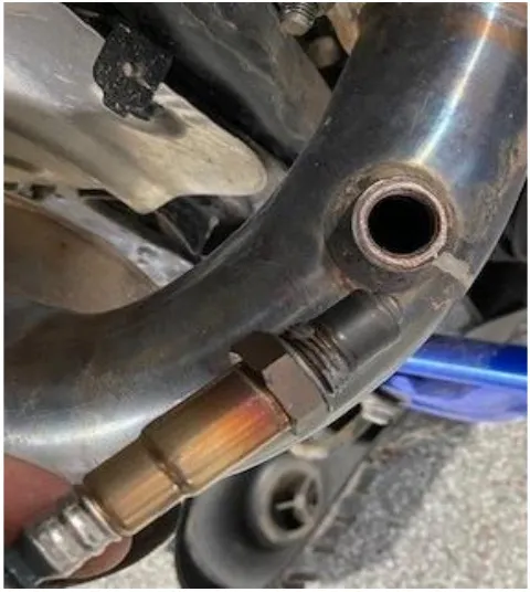
Figure 5 CautionDo not put anything on the tip of the sensor. (Figure 5)
- Step 9
With a 19mm wrench, remove the auxiliary 02 sensor bung plug. Install the 02 sensor into the bung, tighten down with a 22mm wrench.
NoteIF you do NOT have an auxiliary 02 bung located on your exhaust, please read our “Auxilary 02 Bung Instructions”
- Step 10
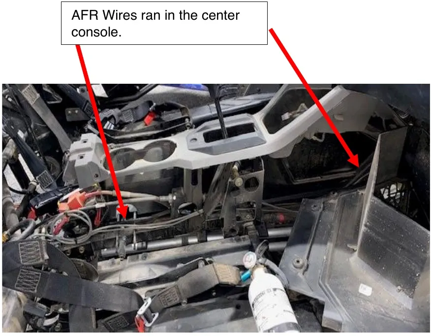
Grab the supplied AFR wiring harness and plug it into the tail of the 02 sensor. Route the wiring harness away from any heat source, rotating parts, and so it won’t snag onto anything while riding. Run it through the rear firewall, underneath the center console supports, next to the shifter, and up to the firewall. If you do not already have an existing hole in your passenger side panel off your center console, drill a hole towards the front of the panel. Feed the AFR wiring harness Through the hole and into the glove box. Once complete, start strapping it with zip ties from the rear to the front. You can keep the access length up front, under the center console. (Figure 6-7)
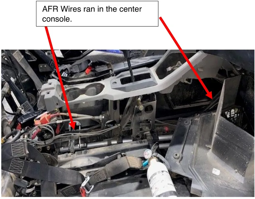
Figure 6 AFR Wires ran in the center console. 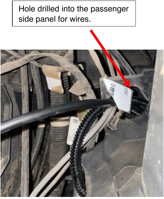
Figure 7 Hole drilled into the passenger side panel for wires. - Step 11
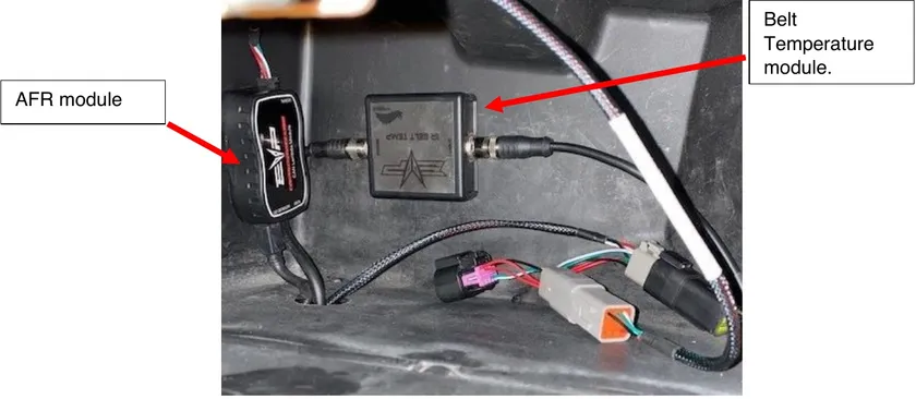
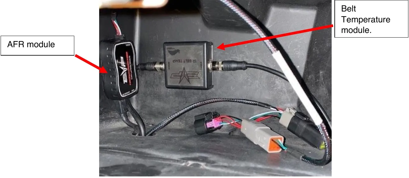
Plug the AFR wiring harness into the AFR module in the glovebox. From the AFR module plug in the grey adaptor to the triple Indy harness (the first or second grey plug). Cut the proper length Velcro and mount the module on the side of the glovebox.
Procedure
Instructions for Belt Temp Module:
- Step 1
If you have not already installed the AFR module, please see step 1-7 above underneath AFR Module. This is the same seven steps it takes to disassemble the car.
- Step 2
Now that the center console is out, glove box is drilled out, and the Polaris diagnostic harness is plugged in, we can continue.
- Step 3
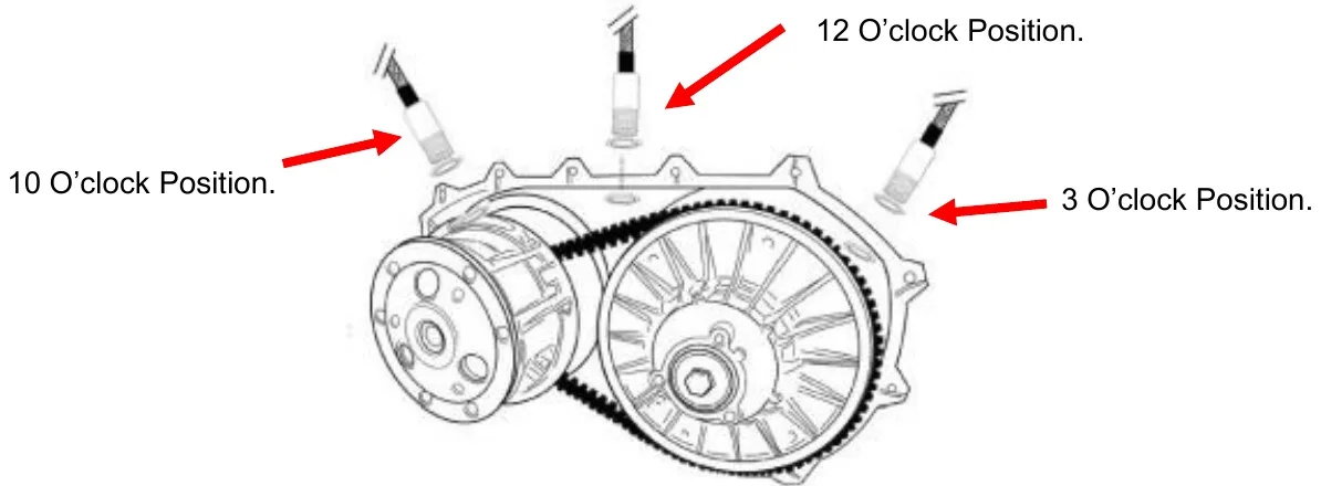
First thing we need to mount the Belt Temperature sensor. Don’t mount the sensor on the clutch cover, otherwise you need to remove it every time you need to maintenance your clutches. The RZR Turbo has a shelf in the middle of the clutch box, which makes the 12 o’clock position not very suitable for mounting. We mounted our Belt Temperature sensor in the 10 o’clock position. (See Figure 7)
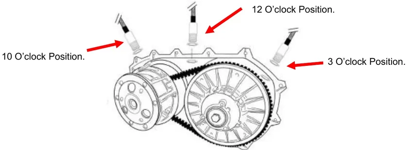
Figure 8 - Step 4
With a hole punch or small diameter drill bit, start an indent on the clutch casing. Once your indent is in the correct location, grab a 1/2” drill bit and drill the hole out. (Figure 8-9)
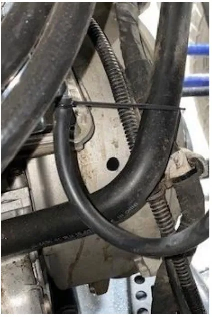
Figure 9, 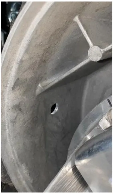 Caution
Make sure the belt sensor is directly in the middle of the belt.
- Step 5
Blow the debris away with compressed air and make sure inside the belt box is clean.
- Step 6
Grab the belt temperature sensor take both nuts off, apply a small amount of Teflon tape (since we are mount the sensor directly to the casting of the clutch box) place one nut on the backside and slide it through the hole. Apply a small amount of Loctite to the threads inside the clutch box. Tighten the second nut on, keep the nut and sensor flush with each other. You do not want the sensor protruding into the clutch box. Take (2) 14mm wrenches and tighten. (Figure 11)
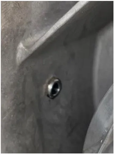
Figure 11 - Step 7
Connect the Belt Temperature wiring harness to the pig tail on the sensor, route the harness through the rear firewall, down center console by the shifter, through the hole in the passenger side panel. Run it up the firewall and through hole in the glovebox where the diagnostic plug and AFR wiring harness did. (Figure 12-13)
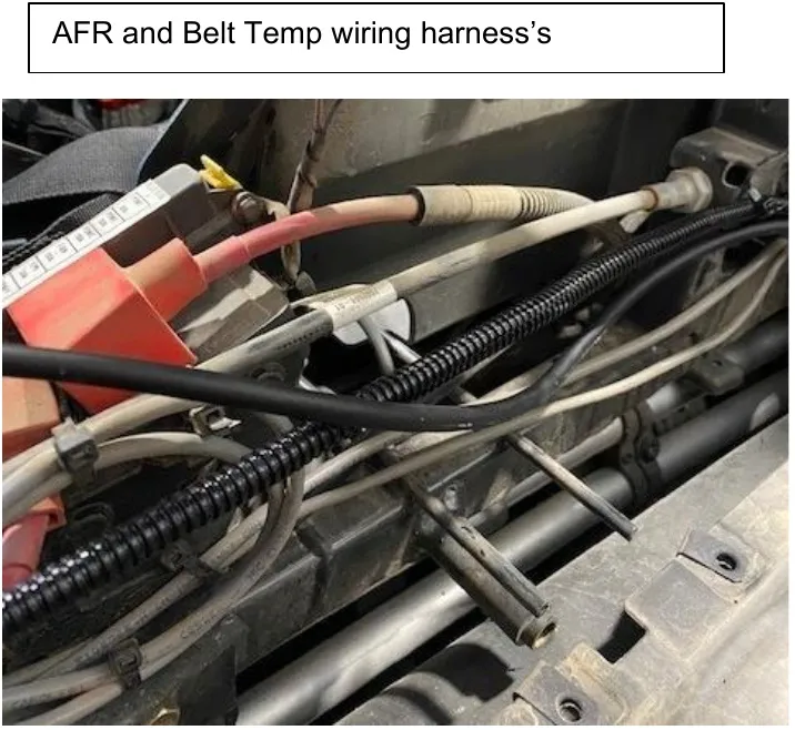
Figure 12 AFR and Belt Temp wiring harness’s 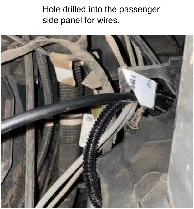
Figure 13 Hole drilled into the passenger side panel for wires. - Step 8
With zip ties, start in the rear of the vehicle and strap the Belt Temperature wiring harness to the frame of the car, keeping the wiring harness away from heat sources and rotating parts.
- Step 9
Connect the Belt Temperature module to the belt wiring harness in the glovebox. From the Belt Temperature module, plug in the grey adaptor to the triple Indy harness (the first or second grey plug). Cut the proper length Velcro and mount the module on the side of the glovebox.
- Step 10
If you would like to keep your glove box and center console sealed, purchase a 1 1/4" rubber gromet (for the glovebox) and a rubber gromet the same diameter you cut in the side panel. On the rubber gromet cut one end from the outside to the middle. Wrap the cables to the inside of the gromet and push it from the bottom of the glovebox in. Once the rubber gromet is seated, run a bead of clear silicone around the outside and middle of the gromet. This will help seal the glovebox. Do the same process for the center console side panel.
Procedure
Reassembly of the Car:
- Step 1
Zip tie any access wire underneath the center console.
- Step 2
Reassemble the center console, pull the shifter boot till they are seated and reconnect the Positive and Ground to the 12 Volt plug. Secure the center console with (8) T-40 Torx bolts and (2) push darts.
- Step 3
Reassemble the firewall and rear access panel.
- Step 4
Reassemble both driver and passenger seats.
- Step 5
Reassemble the clutch cover.
Emissions notice. This product is exempt from the emission standards and related requirements of 40 C.F.R. § 1051 as provided by 40 C.F.R. § 1051.620, and California law [e.g., vehicle code §§ 27156 and 38391]. This product is sold only for use in connection with EPA certified, purpose-built, nonroad vehicles used solely for closed course, nonroad competition/racing and not used for any recreational purpose or on public highways or right of ways maintained by and open to the public. This product is sold only in connection with machines that do not fall under state and/or federal noise or emission standards/regulations. Purchasers who/that purchase this product represent and warrant that the product is purchased only in connection with EPA-certified, emission-regulations-exempt and noise-regulations-exempt competition/racing vehicles as interpreted under applicable state and/or federal law.
Need technical support?
Submit a ticket with your vehicle and what you're seeing, and our support team will get back to you.
