 BUY NOW, PAY LATER. Starting at 0% APR


Can-Am Maverick R Flex Fuel Assembly
Installation instructions for the Maverick R Flex Fuel Assembly on the Can-Am Maverick R (SKU 2532010006). Parts, tools, and full procedure.
Before you start
We decided to add one more safety feature to the EVP Maverick R Flex Fuel system. In addition to the ethanol content display which replaces your factory boost percentage gauge on the info display, we also added a visual indicator if there is a problem with the system. The way it works is if the ECU detects a rapid change in the ethanol content, or if the ECU loses contact with the EVP Ethanol control module, the ethanol content on the BRP information display will flash alternatively between 0 and 100%. In addition, boost and ignition values are reduced to their lowest levels as if there were pure pump gas in the tank. After 30 seconds, if the ethanol content is stable and/or communication with the EVP Ethanol control module is resumed, all ignition and boost settings resume to their appropriate levels for the indicated ethanol content and the ethanol content display will read normally. If the problem persists, the ethanol content will continue to flash and power is limited to the lowest level.
In the box
Parts and tools
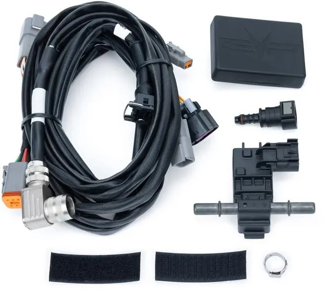
Included parts
- 1Flex Fuel PCB Assembly
- 1Flex Fuel Harness
- 1Flex Fuel Sensor
- 1Hardware Kit
Required tools
- Metric Sockets Set
- Torx Socket Set
- Dielectric Grease
- Rags, Pinch Clamp Tool
Procedure
Installation
- Step 1
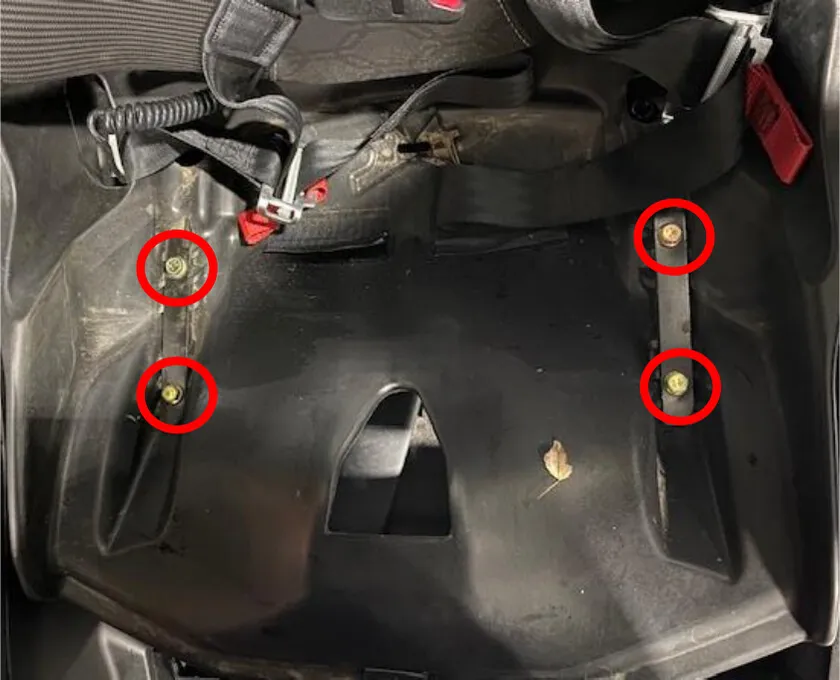
Remove the driver’s seat from the rails. Lift the bottom seat cushion and remove (4) 13mm bolts.
- Step 2
Before fully removing the seat, unplug the seat belt sensor and remove the 18mm bolt holding the harness in place. DON’T CUT THIS HARNESS OFF!

- Step 3
Remove the center tunnel cup holders. Pinch in the middle and pull out (4) clips.

- Step 4
Pop off the driver side upper tunnel panel, you don’t need to remove it. Just pop the panel out of the (4) clips, no need to remove any push darts of T-30 screws.

- Step 5
Remove the driver side tunnel panel. Remove (2) T-30 on the rear and pop the panel out of 3 clips, twist upward. You don’t need to remove this panel, if you would like too remove the panel, remove (1) Gold T-30 on the front side of the panel.

- Step 6
Cut the (3) zip ties holding the fuel line to the plastic molds, from the quick connection backwards.

- Step 7
Place rags under the quick connection. Remove the blue safety clip on the quick connection. Press in the release and split the quick connection joint. With the zip ties cut you can slide the entire rear part of the fuel hose backwards. DO NOT BEND OR KINK THIS HOSE. Cut 2 inches off the male end of the quick connections.

- Step 8
Install the supplied pinch clamp on the hose. Install dielectric grease on the barb side of the supplied female quick connection fitting. Install on the hose, it will take some effort.

- Step 9
Install the flex fuel sensor inline of both female fittings. Reinstall zip ties on the rear fuel line. You can zip tie the flex fuel sensor if you want, it is solid just being put inline.

- Step 10
The harness is labeled below. The boost control portion is not used for this product.

- Step 11
Install the main computer board connector to the black box. Screw it together DON’T OVER TIGHTEN! On the back side of the black box, install one of the Velcro strips.

- Step 12
You can mount the black box anywhere, it is water resistant, but we still recommend mounting it up high. We found under the dash on the body control module (BCM) works well. The harnesses is long enough to mount the box anywhere on the car.

- Step 13
Plug the diagnostic port connection into the diagnostic port. Route the flex fuel sensor connector down the dash to the sensor. Plug it in, make sure to press the grey locking tab in. Coil up the extra wire and unused connectors.
- Step 14
It is best to “key on” the vehicle and check for leaks. You can also hook up your CodeShooter and flash your vehicle to a flex fuel tune and start the vehicle. If no leaks, reinstall all the plastics and seat.
NoteIf flashing your vehicle with CodeShooter, plug directly into the vehicles diagnostic port, NOT the EVP port replicator.


Need technical support?
Submit a ticket with your vehicle and what you're seeing, and our support team will get back to you.
