 BUY NOW, PAY LATER. Starting at 0% APR


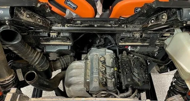
For these instructions we removed the bed and intercooler for better photos. This section of instructions is not needed but does allow for more room. Skip to step 9.
Can-Am Maverick R Billet Intake Manifold
Installation instructions for the Maverick R Billet Intake Manifold on the Can-Am Maverick R (SKU 1542010007). Parts, tools, and full procedure.
In the box
Parts and tools
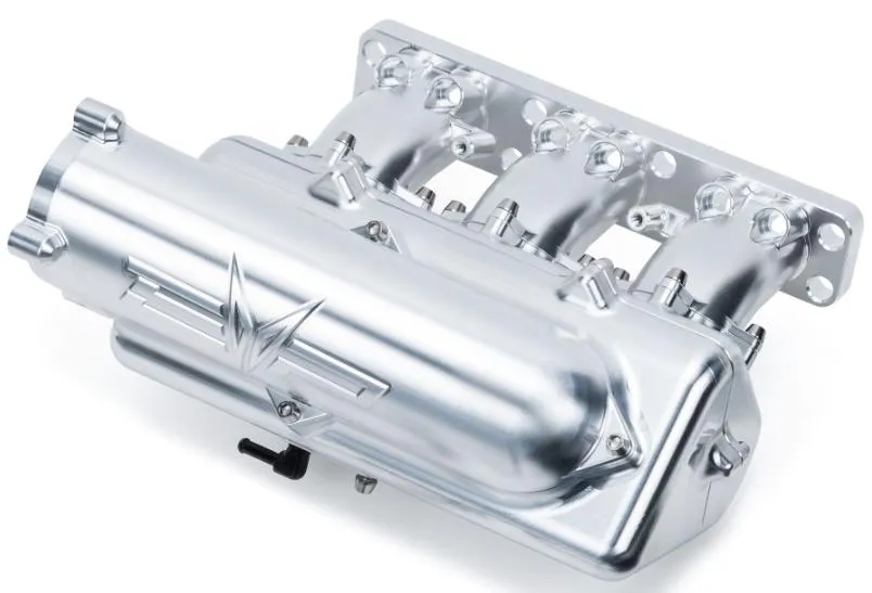
Included parts
- 1Charge Tube Assembly, Black
- 1Intake Manifold Assembly
- 1Intake Manifold Bracket
Required tools
- 8, 10mm Socket
- T-30 Socket
- Dielectric Grease
- Brake Cleaner & Dielectric Grease
Procedure
Installation
- Step 1
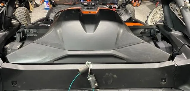
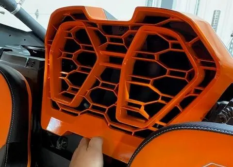
Remove wind dam. (2) push darts and (2) T-30 screws. Pop the front grill out of (4) grommets.
- Step 2
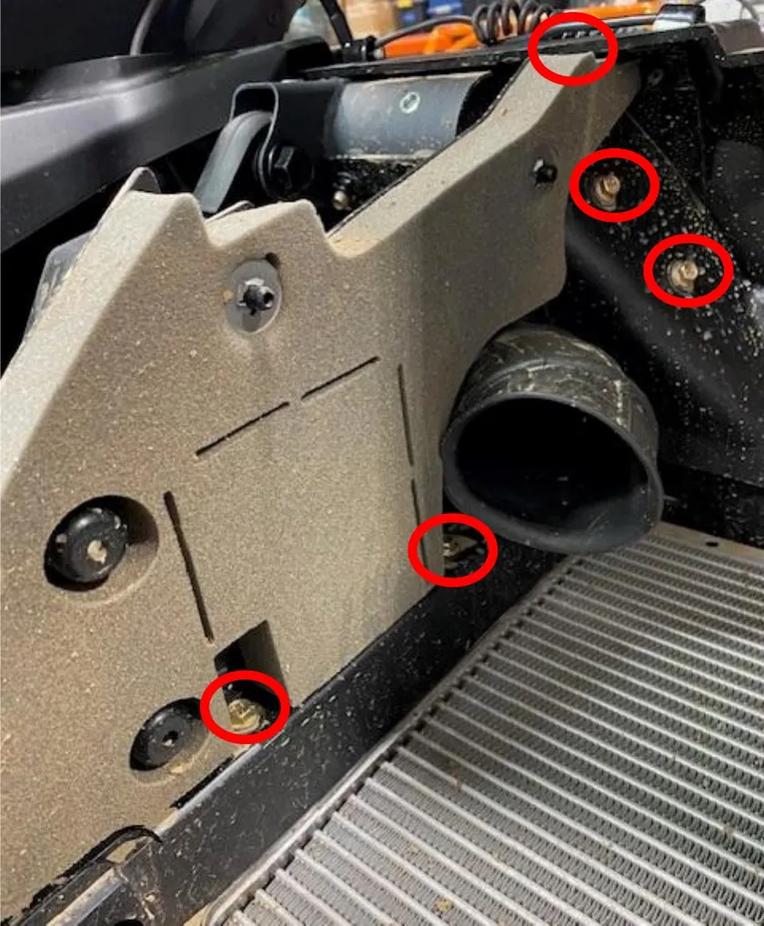
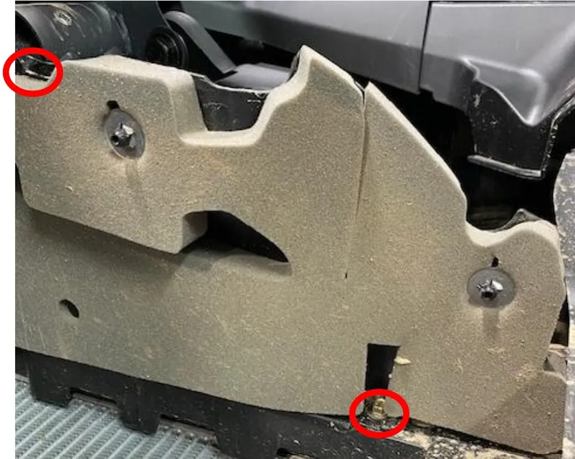
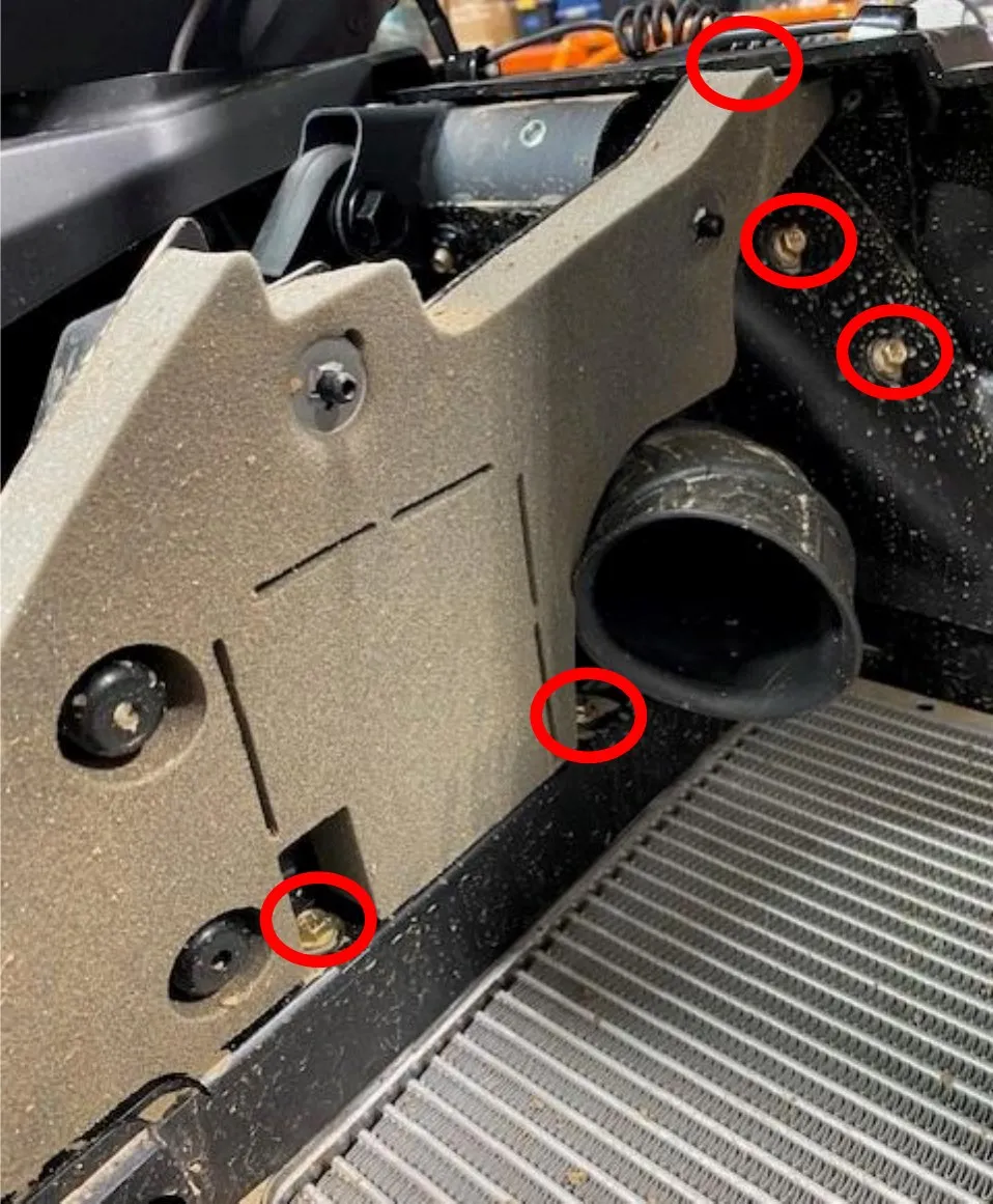
Remove the driver side foam insert. (4) 10mm screws, (1) T-30, push out the intake duct.
- Step 3
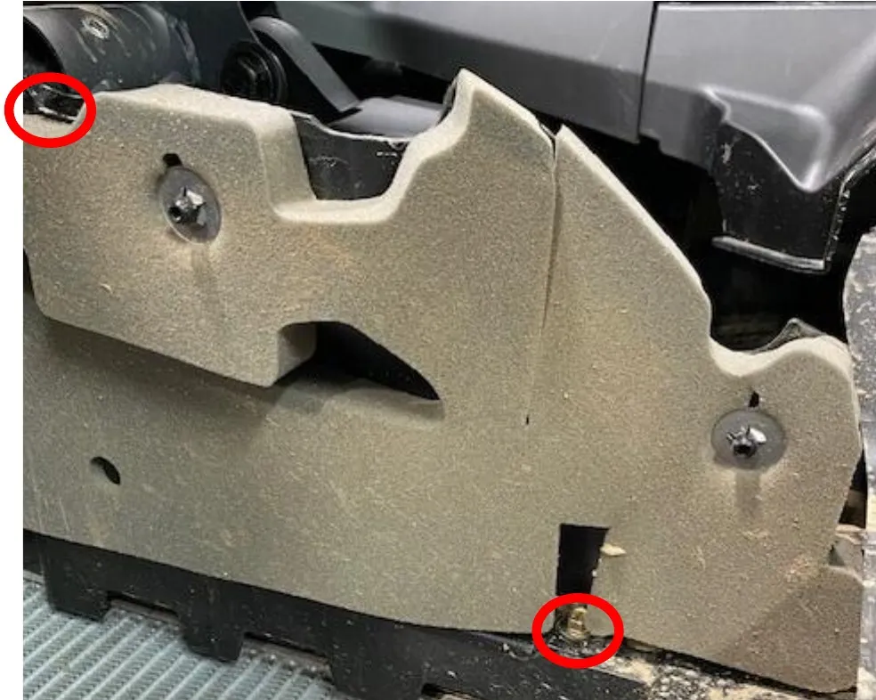
Remove the passenger side foam insert. (3) 10mm screws, (1) T-30.
- Step 4
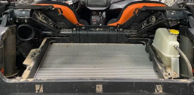
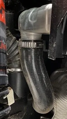
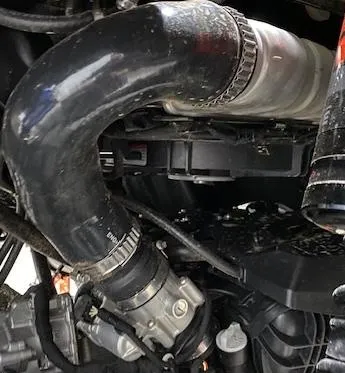
Remove the charge tubes from the intercooler.
- Step 5
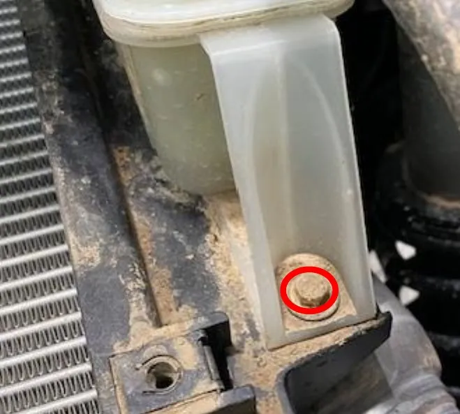
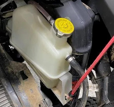
Remove (1) 10mm screw holding the coolant reservoir to the intercooler tray. Pull the reservoir back from the firewall, out of the clip. Strap the reservoir up.
- Step 6
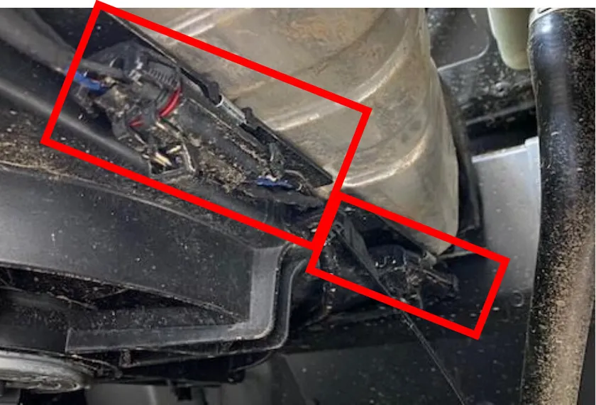
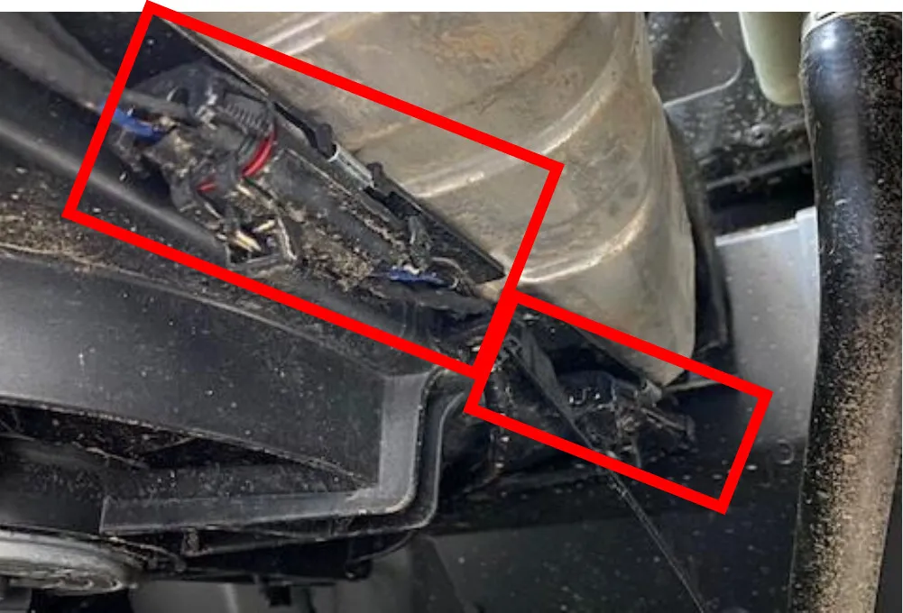
Disconnect both intercooler fans from the OEM harness.
- Step 7
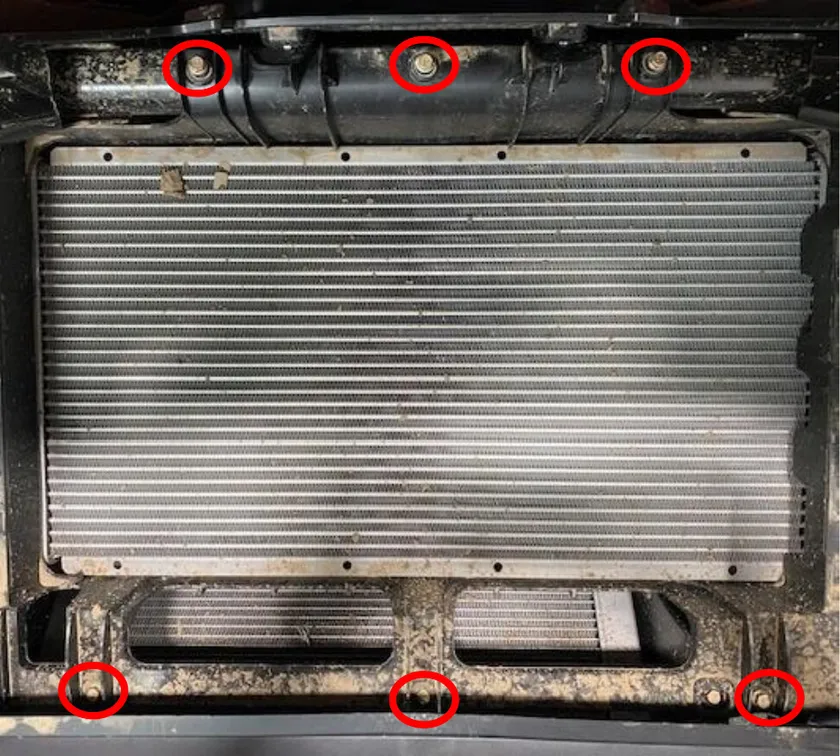
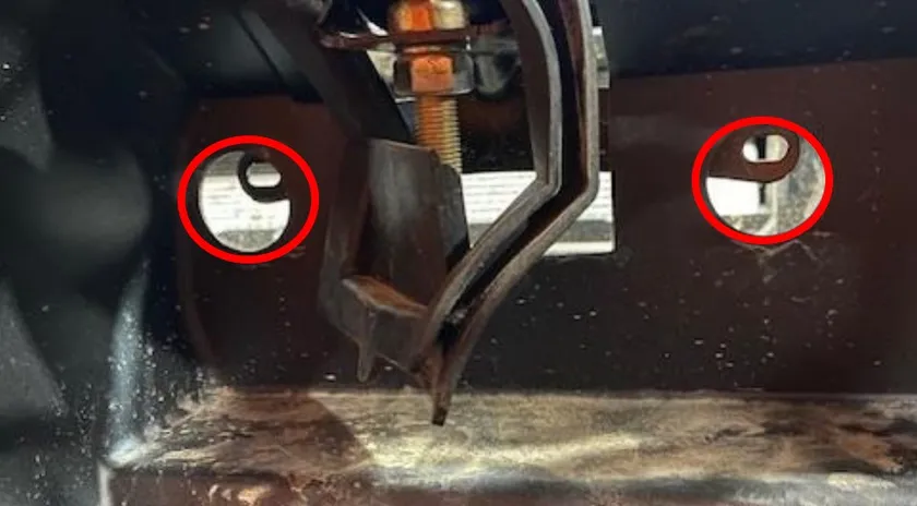
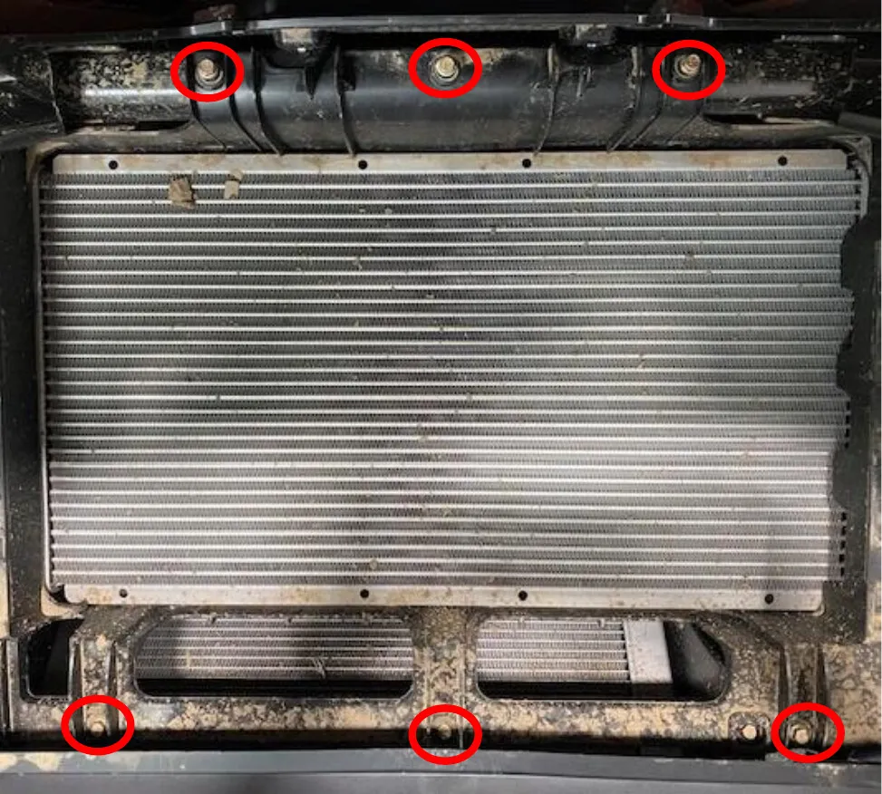
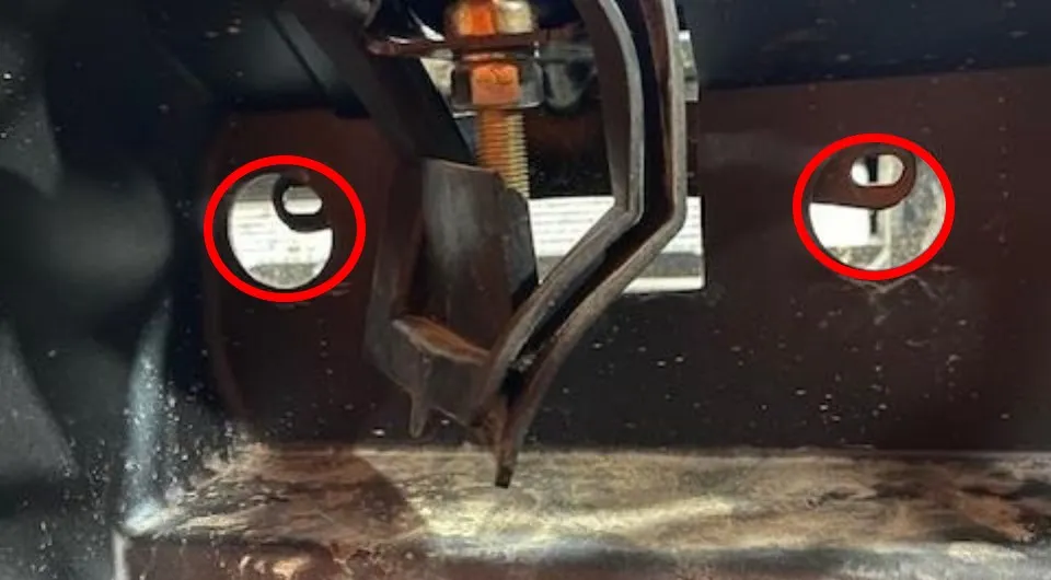
Remove (6) 10mm screws on the intercooler tray. Behind the seats, remove (4) rubber plugs and access (4) 10mm screw. Total of 10 screws.
- Step 8
Remove the intercooler.
- Step 9
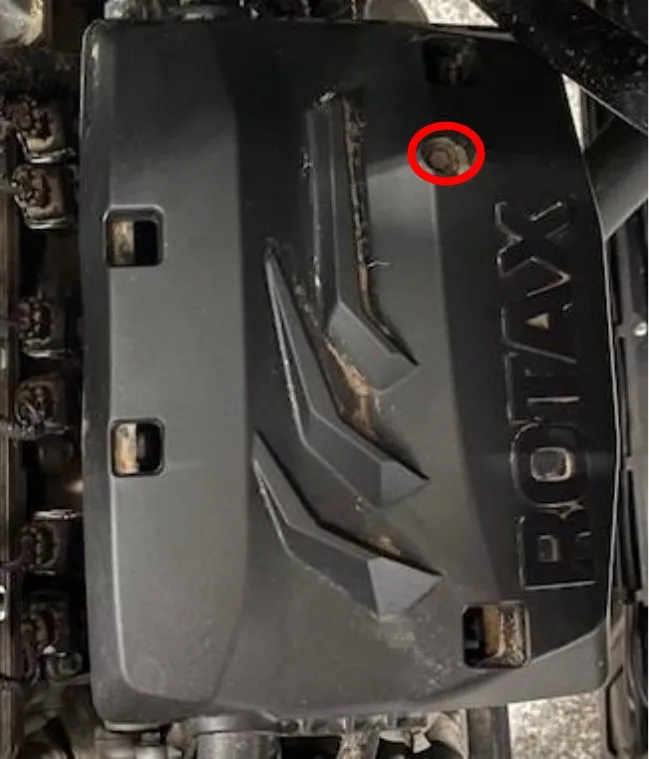
Remove the upper plastic cover on the plenum. (1) 8mm screw.
- Step 10
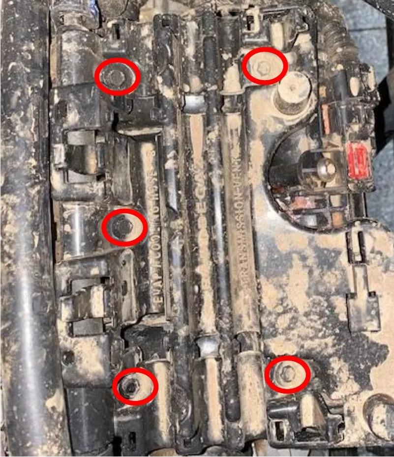
Remove the coolant hose, transmission hose, and EVAP hose if your model is equipped. Remove the lower plastic tray by removing (5) 8mm screws.
- Step 11
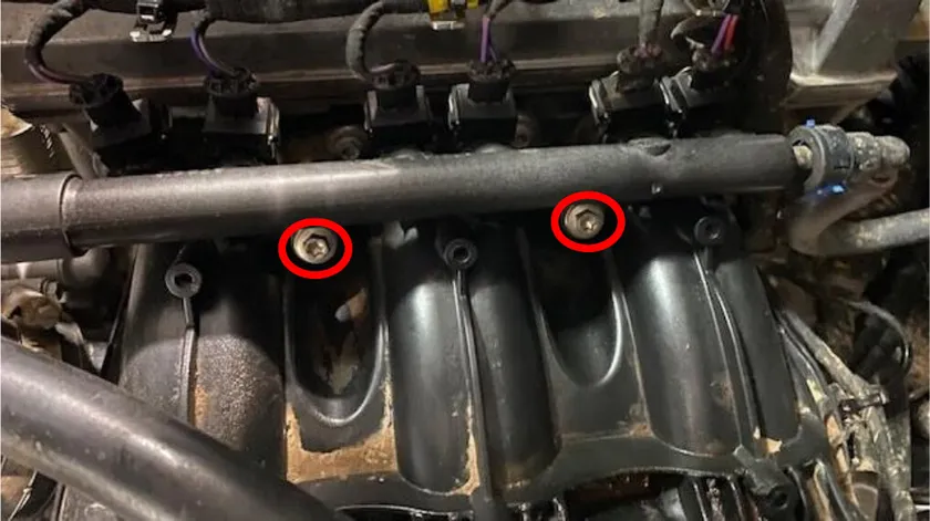
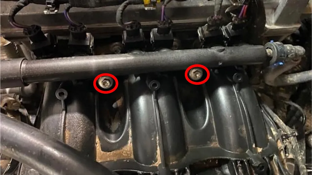
Spray all injector ports and plenum with brake cleaner and compressed air. You do NOT want anything falling into the injector ports. Remove (2) 8mm screws.
- Step 12
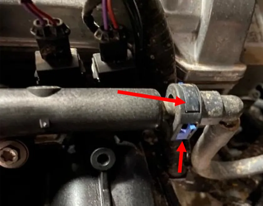
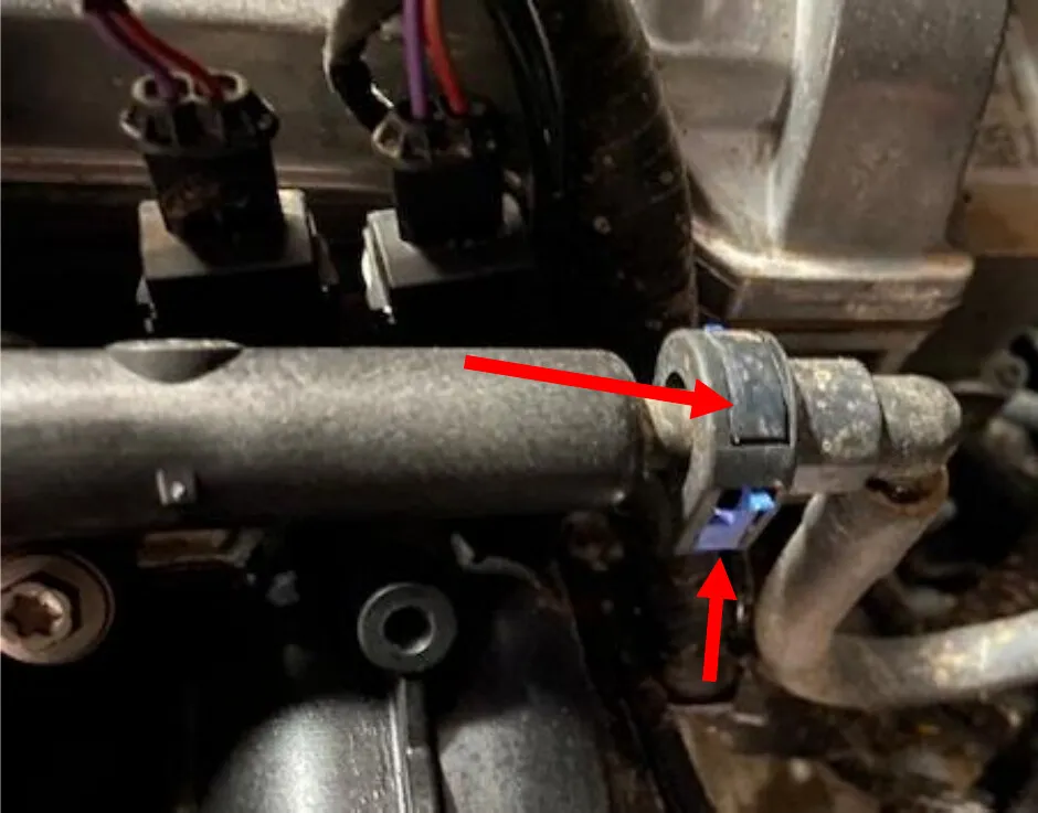
Carefully push down and remove the blue safety clip on the fuel quick connector. DON’T BREAK IT. Press down on the top black connector and remove the fuel hose from the fuel rail.
- Step 13
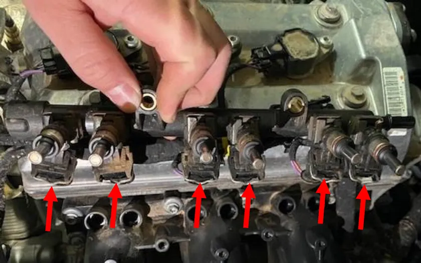
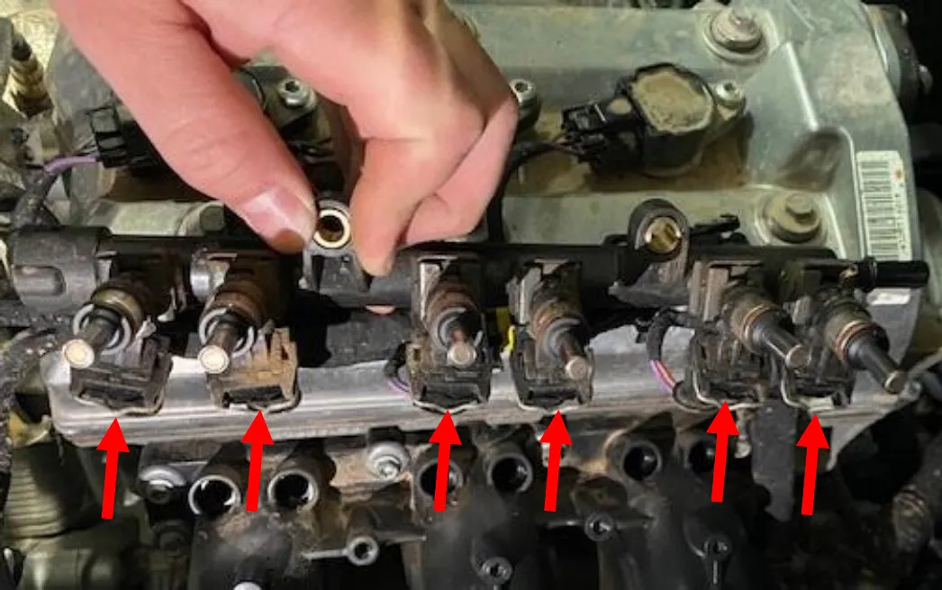
Remove the fuel rail with injectors attached. Flip the fuel rail 180 degrees. Unclip all injector electrical connectors.
- Step 14
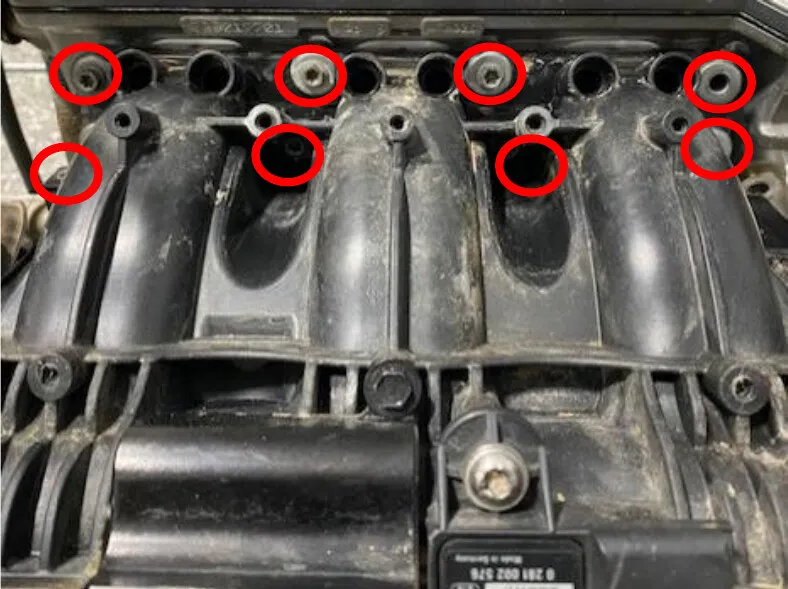
Blow compressed air around the intake manifold where it connects to the head. Remove (8) intake manifold screws with an 8mm socket. The top right screw also has a ground wire connected.
- Step 15
Carefully remove the plenum from the head. Slide the two lower rubber grommets off the studs. Be cautious of the dip stick tube.
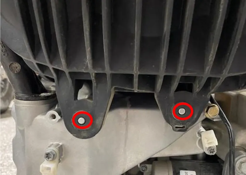
- Step 16
Once the intake plenum is removed, clean all surfaces clean of debris. Look into the head to make sure nothing fell.
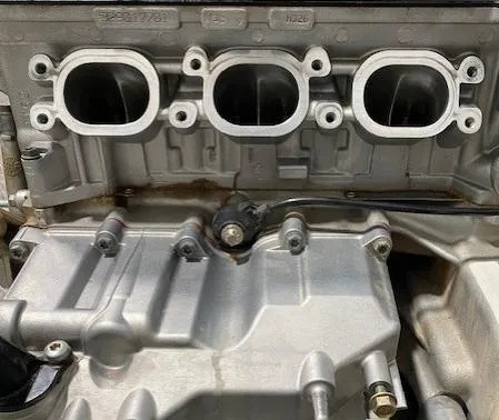
- Step 17
Carefully remove the OEM intake gasket and sleeves. DO NOT TEAR. If gasket is bad, replace it with a new gasket 420450512.
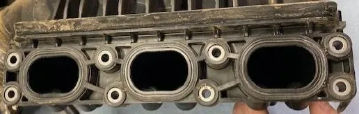
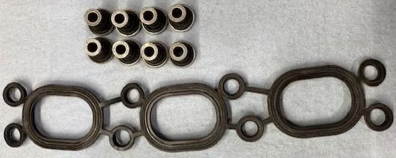
- Step 18
With a clean gasket, apply dielectric grease to the gasket and sleeves and install into the billet plenum.
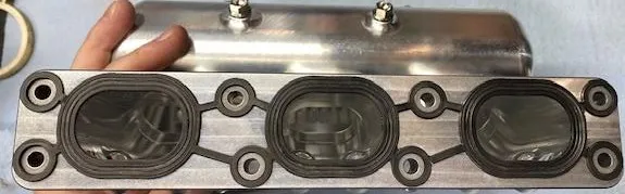
- Step 19
Remove the throttle body from the OEM intake manifold. It is easier to remove the worm drive on the charge tube adapter first.
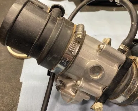
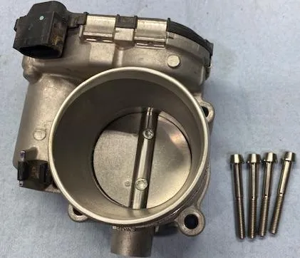
- Step 20
Install the supplied throttle body O-ring into the billet intake manifold. Use dielectric grease.
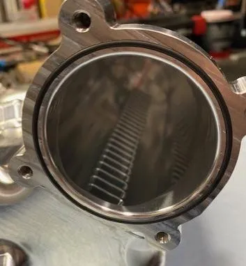
- Step 21
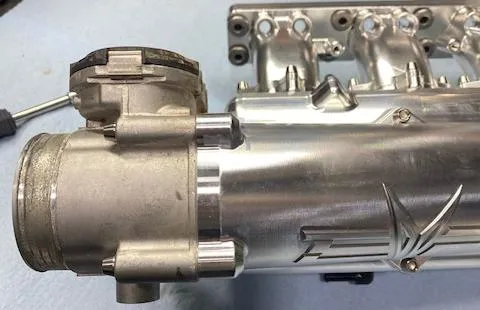
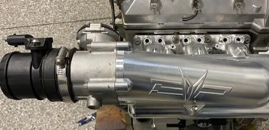
Install the throttle body as shown in the photo below. Use supplied titanium hardware. Torque to 80 in-lb. Reinstall the charge tube adaptor and tighten worm drive.
- Step 22
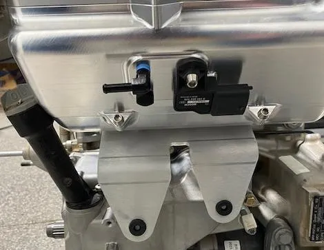
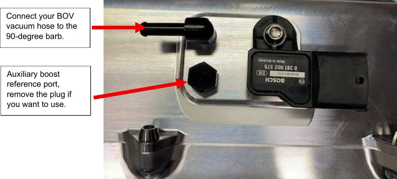
Remove the MAPTS sensor from the OEM intake manifold. Use a T-30 socket. Inspect the sensor, apply dielectric grease and install into the new intake manifold. Use supplied M6x12mm titanium hardware.
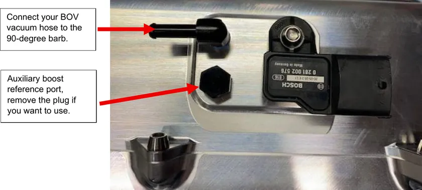
Connect your BOV vacuum hose to the 90-degree barb. Auxiliary boost reference port, remove the plug if you want to use. - Step 23
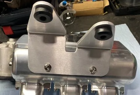
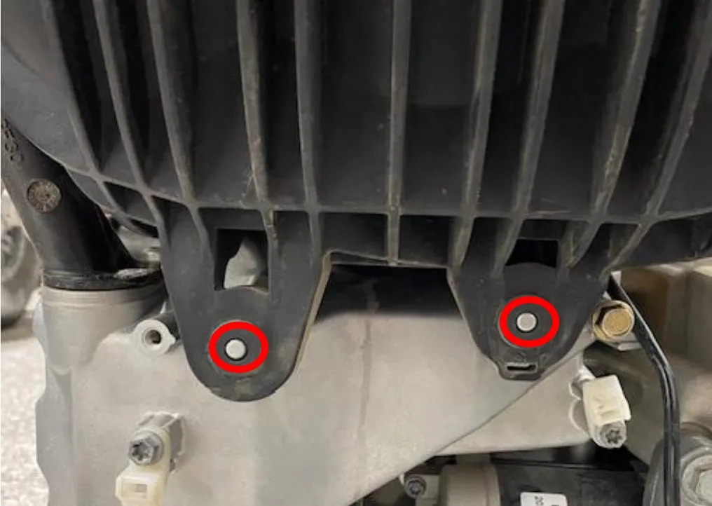
Remove the (2) rubber grommets from the OEM intake manifold. Install them into the bracket supplied. Fasten bracket to the intake manifold with supplied hex hardware.
- Step 24
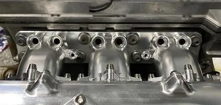
Install the intake manifold onto the vehicle. Align the runner ports and lower bracket grommets onto the studs.
- Step 25
Torque sequence below for intake manifold.
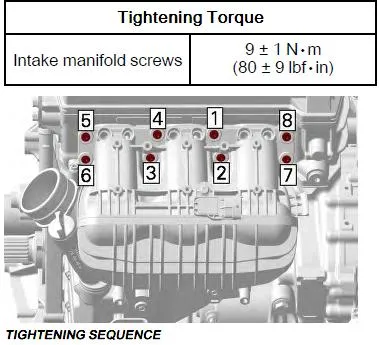
- Torque9 ± 1 N•m (80 ± 9 lbf•in)Intake manifold screws
- Step 26
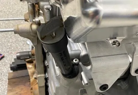
The dip stick tube and plenum will be very close together. You can still check oil levels.
- Step 27
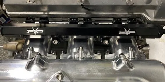
Reinstall the fuel rail, injectors, and connectors. We recommend upgrading to the billet fuel rail.
- Step 28
Install the new charge tube from the intercooler to throttle body, use supplied clamps.
- Step 29
Reinstall all other parts in reverse order.
Need technical support?
Submit a ticket with your vehicle and what you're seeing, and our support team will get back to you.
