 BUY NOW, PAY LATER. Starting at 0% APR


For these instructions we removed the bed and intercooler for better photos. This section of instructions is not needed but does allow for more room. Skip to step 9.
Can-Am Maverick R Billet Fuel Rail
Maverick R Billet Fuel Rail
In the box
Parts and tools

Included parts
- 1Maverick R Fuel Rail, Black
- 3Injector Clip
- 31/4-28 x 3/8 Socket Cap Screw
- 18an ORB Plug
- 18an ORB to 3/8 Quick Connect or 8an ORB to 8an Male Fitting
Required tools
- 8, 10mm Socket
- T-30 Socket
- 8an Wrench
- Brake Cleaner & Dielectric Grease
Procedure
Installation
- Step 1
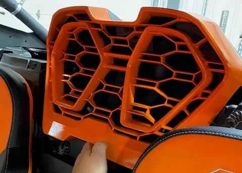
Remove wind dam. (2) push darts and (2) T-30 screws. Pop the front grill out of (4) grommets.

- Step 2
Remove the driver side foam insert. (4) 10mm screws, (1) T-30, push out the intake duct.

- Step 3
Remove the passenger side foam insert. (3) 10mm screws, (1) T-30.

- Step 4
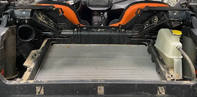
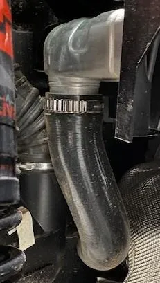
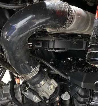
Remove the charge tubes from the intercooler.
- Step 5
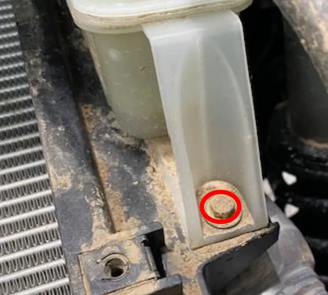
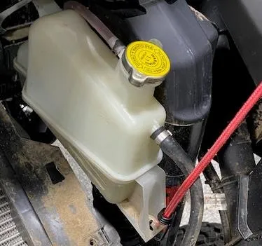
Remove (1) 10mm screw holding the coolant reservoir to the intercooler tray. Pull the reservoir back from the firewall, out of the clip. Strap the reservoir up.
- Step 6
Disconnect both intercooler fans from the OEM harness.

- Step 7
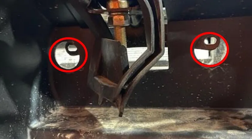
Remove (6) 10mm screws on the intercooler tray. Behind the seats, remove (4) rubber plugs and access (4) 10mm screw. Total of 10 screws.

- Step 8
Remove the intercooler.

- Step 9
Remove the upper plastic cover on the plenum. (1) 8mm screw.

- Step 10
Remove the coolant hose, transmission hose, and EVAP hose if your model is equipped. Remove the lower plastic tray by removing (5) 8mm screws.

- Step 11
Spray all injector ports and plenum with brake cleaner and compressed air. You do NOT want anything falling into the injector ports. Remove (2) 8mm screws.

- Step 12
Carefully push down and remove the blue safety clip on the fuel quick connector. DON’T BREAK IT. Press down on the top black connector and remove the fuel hose from the fuel rail.

- Step 13
Remove the fuel rail with injectors attached. Flip the fuel rail 180 degrees. Unclip all injector electrical connectors.

- Step 14
Remove all (6) injector clips. Remove injectors and clean O-rings.

- Step 15
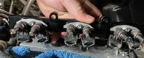
Install the 3/8 quick connect fitting (or -8an) and 8an plug. Make sure the O-rings are seated and not pinched. Use dielectric grease on all injector O-rings. Install the injector clips into the small cut outs on the injectors. They will sit flush. Tighten down with supplied socket cap screws.


- Step 16
Reinstall all (6) injector electrical connectors. Make sure they click into place.
- Step 17
Reinstall the quick connect fuel line to the fuel rail. Reinstall the blue safety clip. Mount the fuel rail using (2) OEM screws. Cycle the key a few times and check for leaks.

- Step 18
Reinstall the plastic hose supports if you prefer. You can also install the billet hose supports, reusing OEM hardware.

- Step 19
Reinstall all other parts in reverse order.




Emissions notice. This product is exempt from the emission standards and related requirements of 40 C.F.R. § 1051 as provided by 40 C.F.R. § 1051.620, and California law [e.g., vehicle code §§ 27156 and 38391]. This product is sold only for use in connection with EPA certified, purpose-built, nonroad vehicles used solely for closed course, nonroad competition/racing and not used for any recreational purpose or on public highways or right of ways maintained by and open to the public. This product is sold only in connection with machines that do not fall under state and/or federal noise or emission standards/regulations. Purchasers who/that purchase this product represent and warrant that the product is purchased only in connection with EPA-certified, emission-regulations-exempt and noise-regulations-exempt competition/racing vehicles as interpreted under applicable state and/or federal law.
Need technical support?
Submit a ticket with your vehicle and what you're seeing, and our support team will get back to you.
