 BUY NOW, PAY LATER. Starting at 0% APR


Operating RPM: 7200
Can-Am Defender Tuned & DT-130-195 Clutch Kit
Installation instructions for the Defender Tuned & DT-130-195 Clutch Kit on the Can-Am Defender. Parts, tools, and full procedure.
Before you start
Can Am Defender XMR Sport/Trail (401FC0010)
| Year | Model | Tune | Clutch Weights | 1 Weight in Grams |
|---|---|---|---|---|
| 2019-2021 | XMR | Untuned | (4) Gold Fixed | 48.8g |
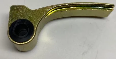
Can Am Defender XMR Sport/Trail (401FC0009)
| Year | Model | Tune | Clutch Weights | 1 Weight in Grams |
|---|---|---|---|---|
| 2019-2021 | XMR | Tuned | (6) Gold Fixed | 48.8g |
Can Am Defender Non XMR (401FC0008)
| Year | Model | Tune | Clutch Weights | 1 Weight in Grams |
|---|---|---|---|---|
| 2016-2021 | Non XMR | Untuned | (3) Adjustable | 37.8g |
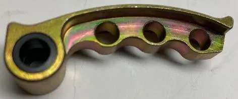
Can Am Defender Non XMR (401FC0000)
| Year | Model | Tune | Clutch Weights | 1 Weight in Grams |
|---|---|---|---|---|
| 2016-2019 | Non XMR | Tuned | (3) Adjustable (3) Non-Adjustable | Adjustable 37.8g Non-Adjust 32.4g |
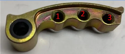
Adjustable Weights
| 1 Weight | 3/16 | 1/4 | 3/8 |
|---|---|---|---|
| 37.8g | .6g | .8g | 1.5g |
| Tune | Hole 1 | Hole 2 | Hole 3 |
|---|---|---|---|
| 2 Seat, 30” Tire | (2)1/4 ss | (2) 1/4 ss | (2) 1/4 ss |
| 2 Seat, 33”+ Tire | (2) 1/4 ss | (2) 3/16 ss | (2) 3/16 ss |
| 4 Seat, 30”+ Tire | (2) 1/4 ss | (2) 1/4 ss | (2) 1/4 ss |
Can Am Defender Non XMR (401FC0015)
| Year | Model | Tune | Clutch Weights | 1 Weight in Grams |
|---|---|---|---|---|
| 2020+ | Non XMR | Tuned | (4) Adjustable (2) Non-Adjustable | Adjustable 37.8g Non-Adjust 32.4g |
Operating RPM: 6800
Adjustable Weights
| 1 Weight | 3/16 | 1/4 | 3/8 |
|---|---|---|---|
| 37.8g | .6g | .8g | 1.5g |
| Tune | Hole 1 | Hole 2 | Hole 3 |
|---|---|---|---|
| 2 Seat, 30” Tire | (2)1/4 ss | (2) 1/4 ss | (2) 1/4 ss |
| 2 Seat, 33”+ Tire | (2) 1/4 ss | (2) 3/16 ss | (2) 3/16 ss |
| 4 Seat, 30”+ Tire | (2) 1/4 ss | (2) 1/4 ss | (2) 1/4 ss |
Can Am Defender Non XMR Turbocharger (401FC0015)
| Year | Model | Tune | Clutch Weights | 1 Weight in Grams |
|---|---|---|---|---|
| 2020+ | Non XMR | Turbo Tuned | (4) Adjustable (2) Non-Adjustable | Adjustable 37.8g Non-Adjust 32.4g |
Operating RPM: 7300-7500
Adjustable Weights
| 1 Weight | 3/16 | 1/4 | 3/8 |
|---|---|---|---|
| 37.8g | .6g | .8g | 1.5g |
| Tune | Hole 1 | Hole 2 | Hole 3 |
|---|---|---|---|
| 2 Seat, 28”- 30” Tire | (2)1/4 ss | 0 | 0 |
| 2 Seat, 33”- 35” Tire | (2) 3/16 ss | 0 | 0 |
| 4 Seat, 28” - 30” Tire | 0 | 0 | 0 |
| 4 Seat, 33”- 35” Tire | 0 | 0 | 0 |
In the box
Parts and tools
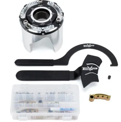
Included parts
- 1Hardware Kit
- 1Intercooler to throttle body silicone
- 1Intercooler to Turbo Silicone
- 1Blow off valve (optional)
Required tools
- Screwdriver(s)
- Pinch Clamp Tool
- 11mm Socket
- Dielectric Grease (optional)
Procedure
Cam Arm Removal and Installation Without Removing Primary Clutch
- Step 1
Remove clutch cover and belt.
- Step 2
For OEM cam arm removal, use a T25 Torx bit on one end of the pin and an 8mm socket on the other and remove the nut.
- Step 3
Remove the pin.
- Step 4
Use a screwdriver to open the sheaves and a magnet to retrieve the cam arm SEE PICTURES BELOW– be careful to save the washers that are installed on both sides of the arm – these will be needed if you ever use the stock weights again. They are NOT needed for the installation of the EVP weights.
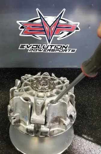
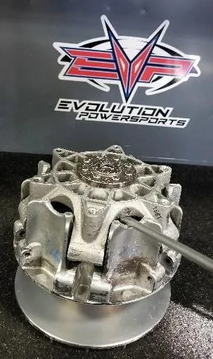
- Step 5
To install the new cam arms, slide an arm into the location where the previous arm was installed. Use a magnet to position the arm so the pin can be reinstalled. Reinstall nut onto pin.
Note
Primary clutches need to be perfectly aligned. If you place a non-adjustable weight in the clutch, across from it needs to be a non-adjustable weight. Same for adjustable weights.
Procedure
Installation of the Helix and Spring
- Step 1
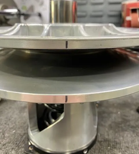
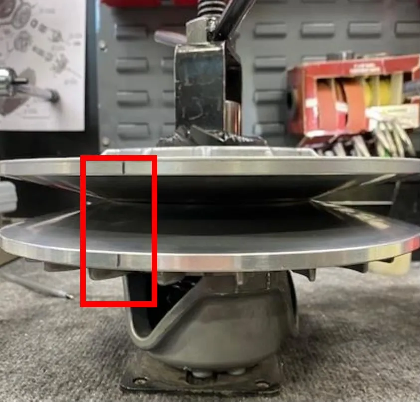
Remove the secondary clutch with a 17mm socket and impact, mount it into a clutch compression tool. With a sharpie make alignment marks on both sheaves. (Figure 1)
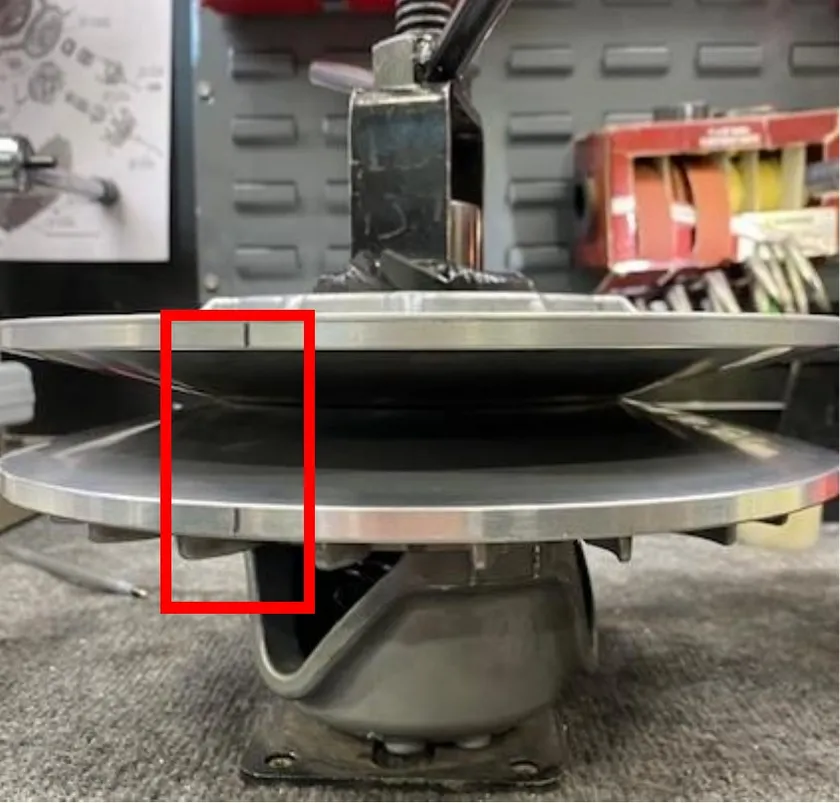
Fig. 1 - Step 2
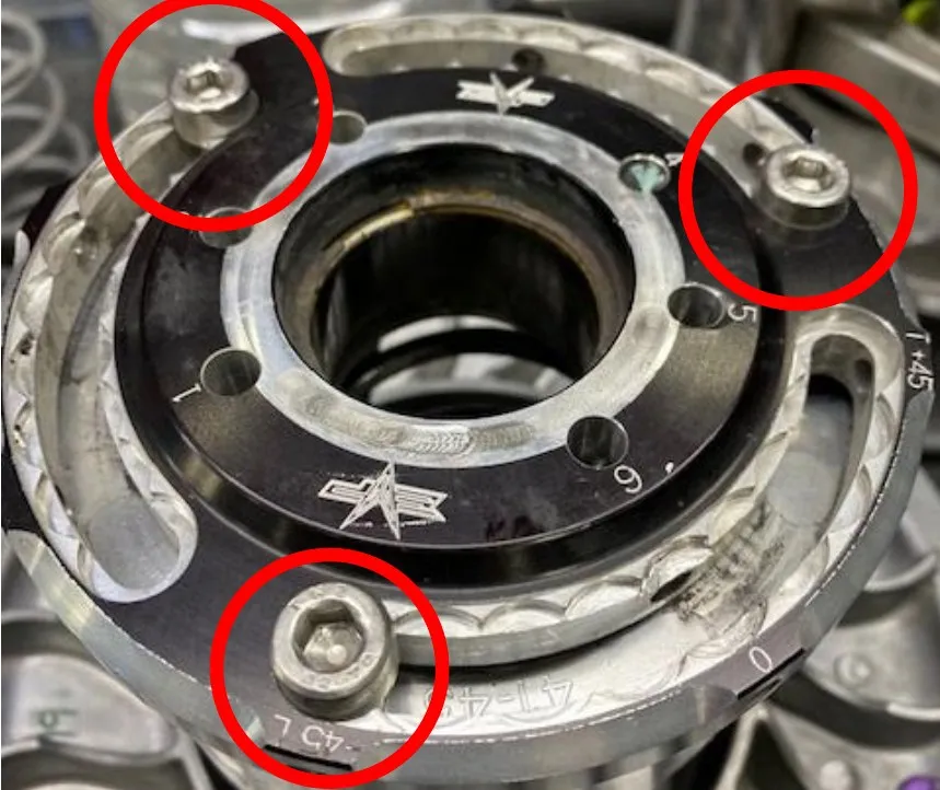
Use 13mm socket to take 3 fasteners out of the helix and carefully loosen the spring compression tool to remove tension. (Figure 2)
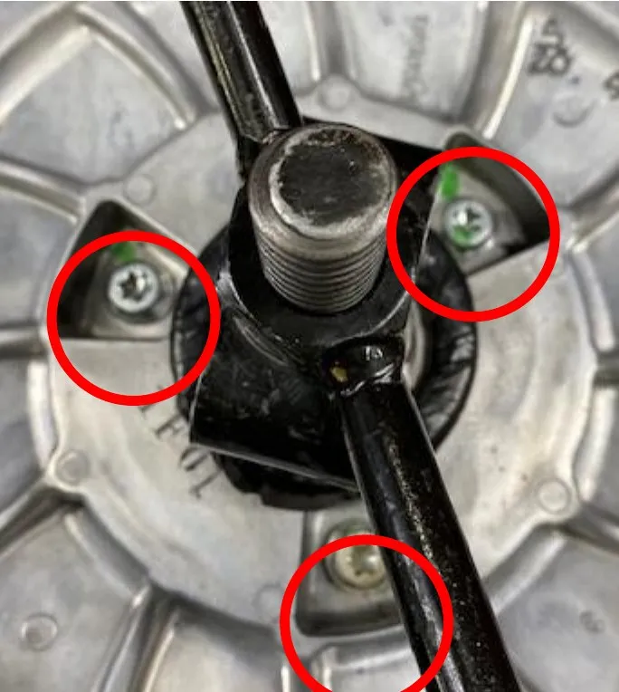
Fig. 2 - Step 3
Pull off both sheaves, remove spring cup and spring from the OEM helix.
- Step 4
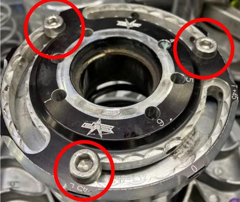
Grab the new helix, make sure the helix cap is adjusted to -45 degrees, if not loosen (3) Allen screws and clock the helix cap. Tighten the (3) Allen screws back down.
- Step 5
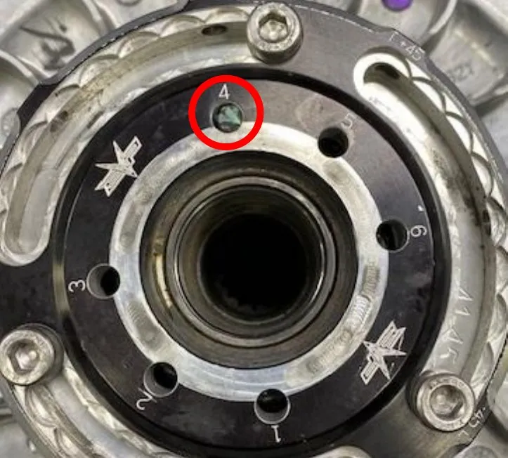
Reassemble the secondary clutch on the clutch compression tool in this order: Helix assembly, stock spring in hole 4 (EVP Purple Spring hole 5), spring cap, both sheaves in alignment. When compressing make sure the rollers are in line with the helix ramps. You may need to adjust with your hands while compressing.
- Step 6
Apply Red Loctite onto the threads of the (3) 13mm bolts holding the helix to the sheaves.
- Step 7
Reinstall the clutch on the vehicle and torque secondary bolt to 52 ft-lbs.
- Step 8
Using the Can Am belt changing tool with EVP non-marring tip reinstall belt.
- Step 9
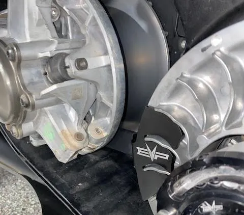
Install the secondary holding tool onto the secondary, align the tool in between the fins. Allow the handle to rest against the primary bearing. (Some Defenders have a different moveable sheave that wont fit the holding tool).
- Step 10
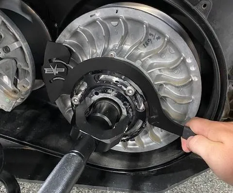
Install the helix wrench into a slot around the Shift-Tek helix cap.
Procedure
Installation
- Step 4
Loosen all (3) M6 Allen head cap screws (do not remove). Apply pressure onto the helix wrench. You can now turn the helix cap to add or subtract torsion pressure on the spring. Once complete tighten the (3) M6 Allen head cap screws.
- Step 5
Remove the helix wrench and secondary holder. Install the belt back onto the clutches. Remove the belt changing tool and spin the secondary a total of 5 times.
Emissions notice. This product is exempt from the emission standards and related requirements of 40 C.F.R. § 1051 as provided by 40 C.F.R. § 1051.620, and California law [e.g., vehicle code §§ 27156 and 38391]. This product is sold only for use in connection with EPA certified, purpose-built, nonroad vehicles used solely for closed course, nonroad competition/racing and not used for any recreational purpose or on public highways or right of ways maintained by and open to the public. This product is sold only in connection with machines that do not fall under state and/or federal noise or emission standards/regulations. Purchasers who/that purchase this product represent and warrant that the product is purchased only in connection with EPA-certified, emission-regulations-exempt and noise-regulations-exempt competition/racing vehicles as interpreted under applicable state and/or federal law.
Need technical support?
Submit a ticket with your vehicle and what you're seeing, and our support team will get back to you.
