 BUY NOW, PAY LATER. Starting at 0% APR


Can-Am Defender 1000 Catch Can
Installation instructions for the Defender 1000 Catch Can on the Can-Am Defender (SKU 803FC0013). Parts, tools, and full procedure.
In the box
Parts and tools
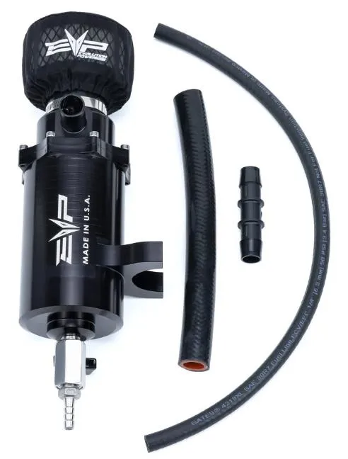
Included parts
- 1EVP Catch Can
- 15/8” Silicone Hose
- 15/8” Straight Coupler
- 2M8 Oversized Washer
- 2M8 x 16mm Button Head
- 11/4” Fuel Hose
Required tools
- Screwdriver
- T-30 Torx
- 5/16” Drill Bit
- Pinch Clamp Tool (optional)
Procedure
Installation
- Step 1
Remove the driver side seat, or passenger driver side if a 4 door. Remove 4 push darts and pull back the soundproof material.
- Step 2
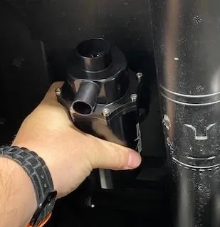
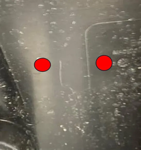
Hold the catch can up on the backside of the fire wall. Make sure the catch can is above the crankcase hose. Measure the holes out and mark them on the firewall.
- Step 3
With a 5/16” drill bit, drill out both holes on the firewall. Mount the catch can, use both M8 screws and oversized washers on the inside of the firewall.
- Step 4
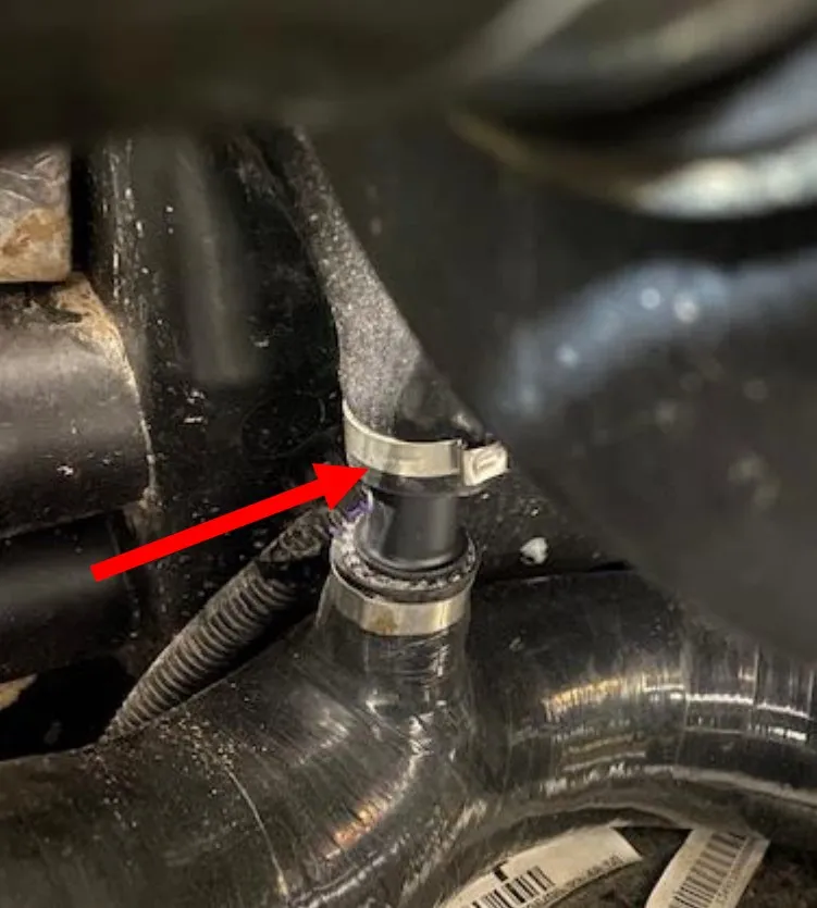
If you are running a turbocharger kit, remove the crankcase breather hose off the intake tube. Use supplied 3/4" silicone cap over the fitting on the intake tube. Use supplied pinch clamp. If you’re not running a turbo kit, remove the crankcase breather hose and cap the OEM intake tube.
- Step 5
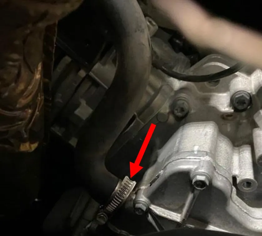
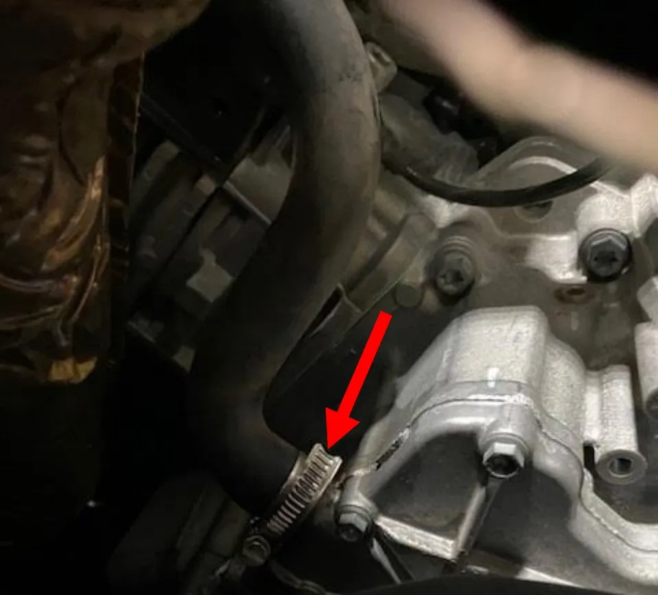
Loosen the worm drive holding the crankcase breather hose on, rotate the hose towards the driver side of the vehicle. Tighten clamp back up. Keep hose in OEM plastic support.
- Step 6
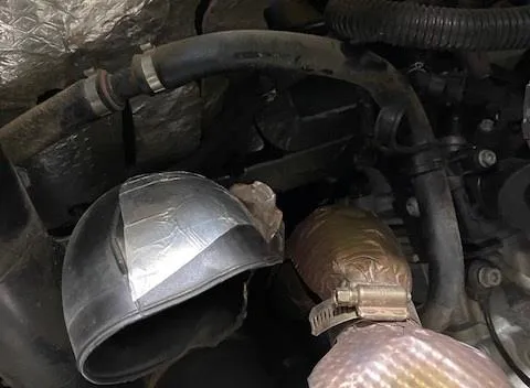
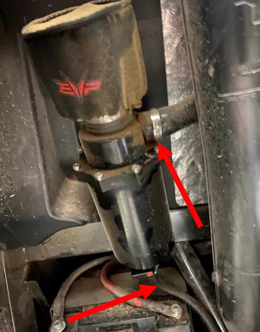
If not running a turbocharger, install the supplied 5/8” coupler and hose to the crankcase vent hose. Use supplied pinch clamps. If running a turbocharger, this hose is already added, just route hose to catch can.
- Step 7
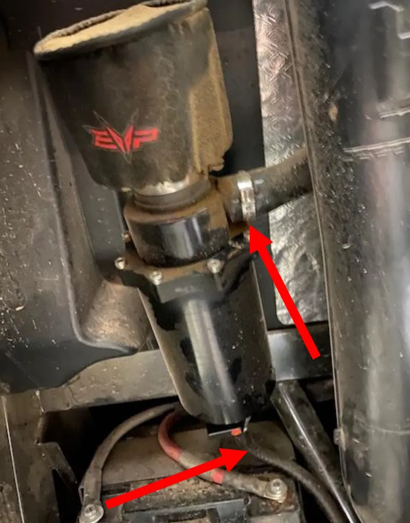
Route the crankcase hose behind the plastic duct. Route the drain hose down to the belly pan.
Need technical support?
Submit a ticket with your vehicle and what you're seeing, and our support team will get back to you.
