 BUY NOW, PAY LATER. Starting at 0% APR


CF Moto Z10 Charge Tube Kit
CF Moto Z10 Charge Tube Kit
In the box
Parts and tools
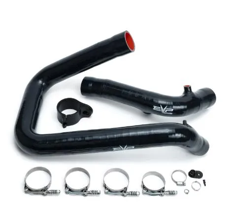
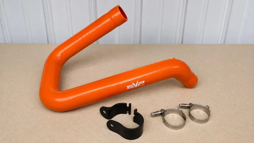
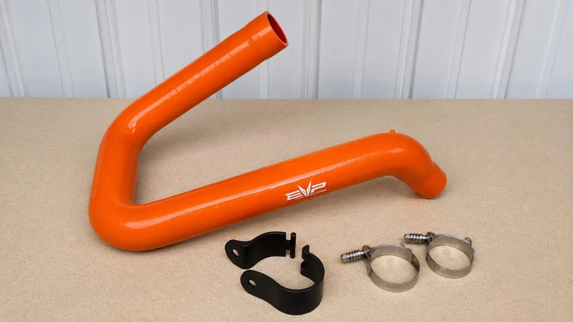
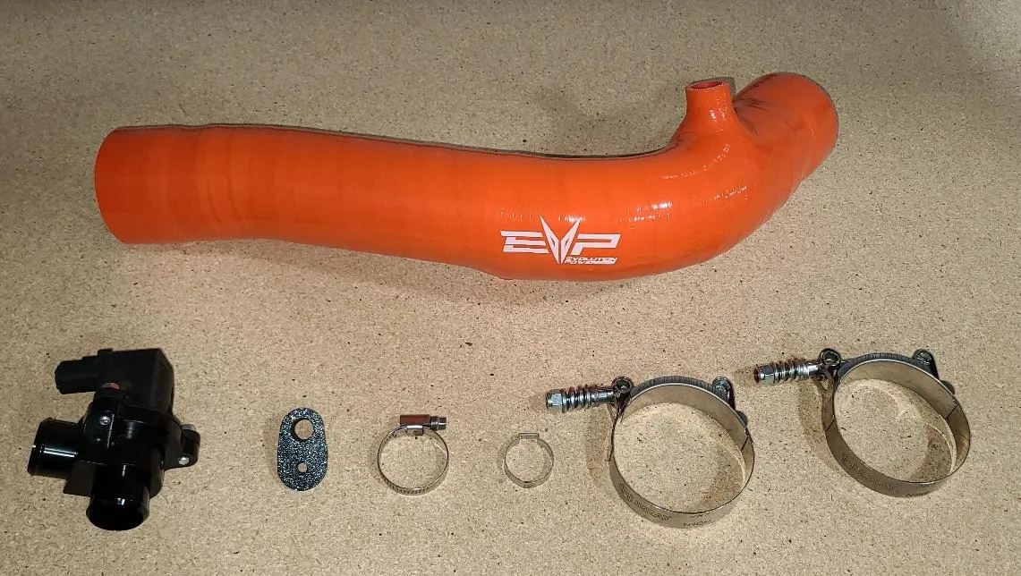
Included parts
- Charge Tube Set
- Hardware Assembly
- Charge Tube Support
Required tools
- Screwdrivers
- Pinch Clamp Tool
- 11mm Socket
Procedure
Installation
- Step 1
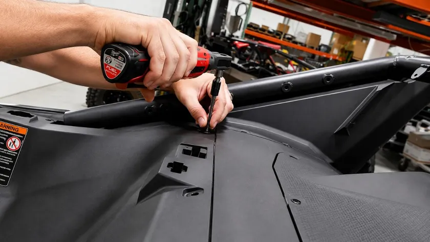
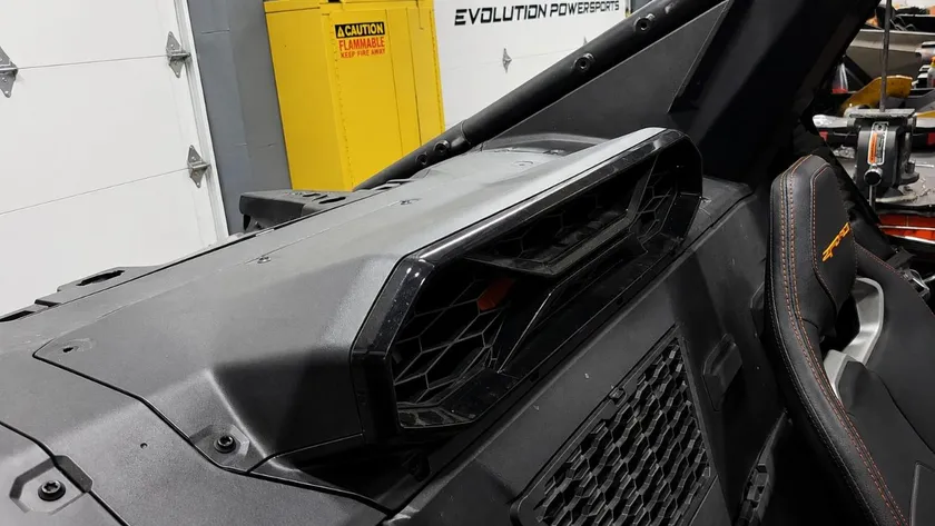
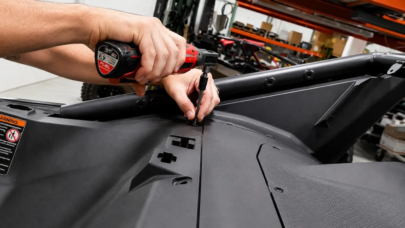
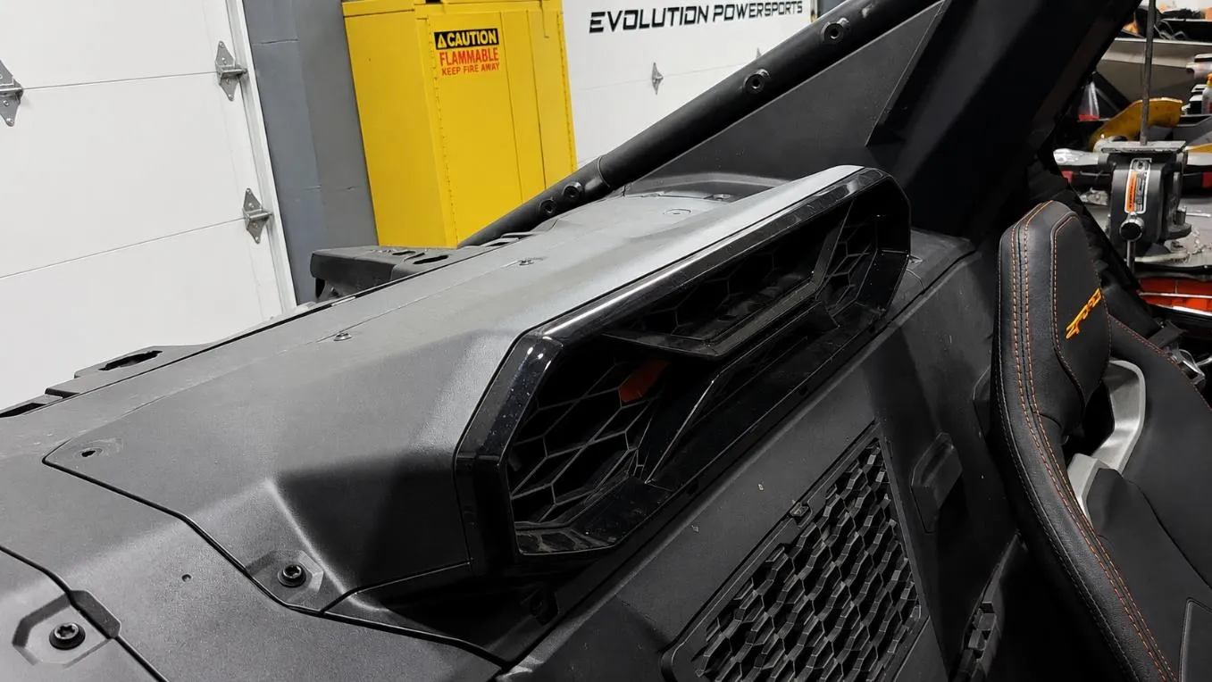
Remove bed and plastic’s surrounding the intercooler.
- Step 2
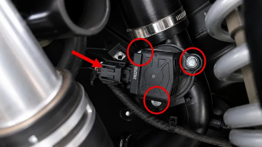
Unplug the factory BRV connector and remove (3) 8mm bolts holding BRV onto the charge tube.
- Step 3
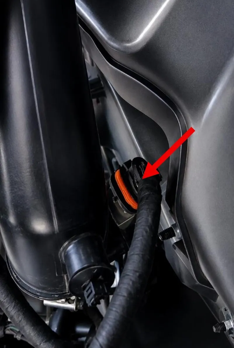
Disconnect the plug on the MAP sensor, located on the backside of charge tube.
- Step 4
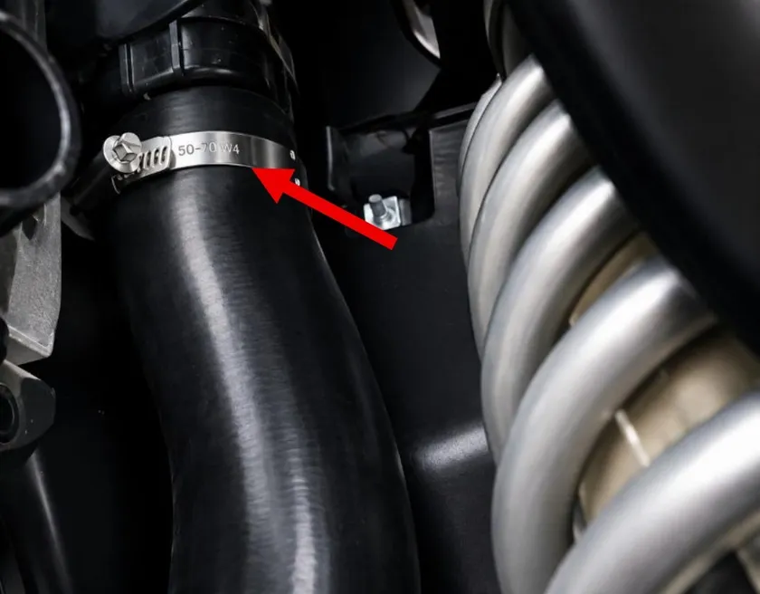
Remove the upper and lower charge tube clamps and remove charge tube.
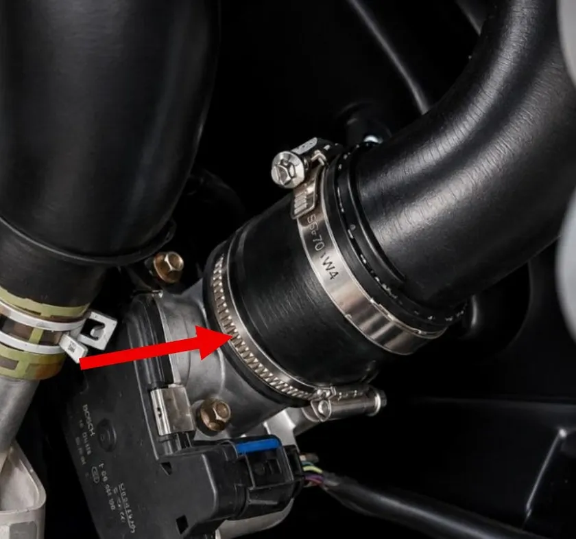
- Step 6
Remove the charge tube clamp from turbocharger and aluminum adaptor. Remove the first half of the charge tube.
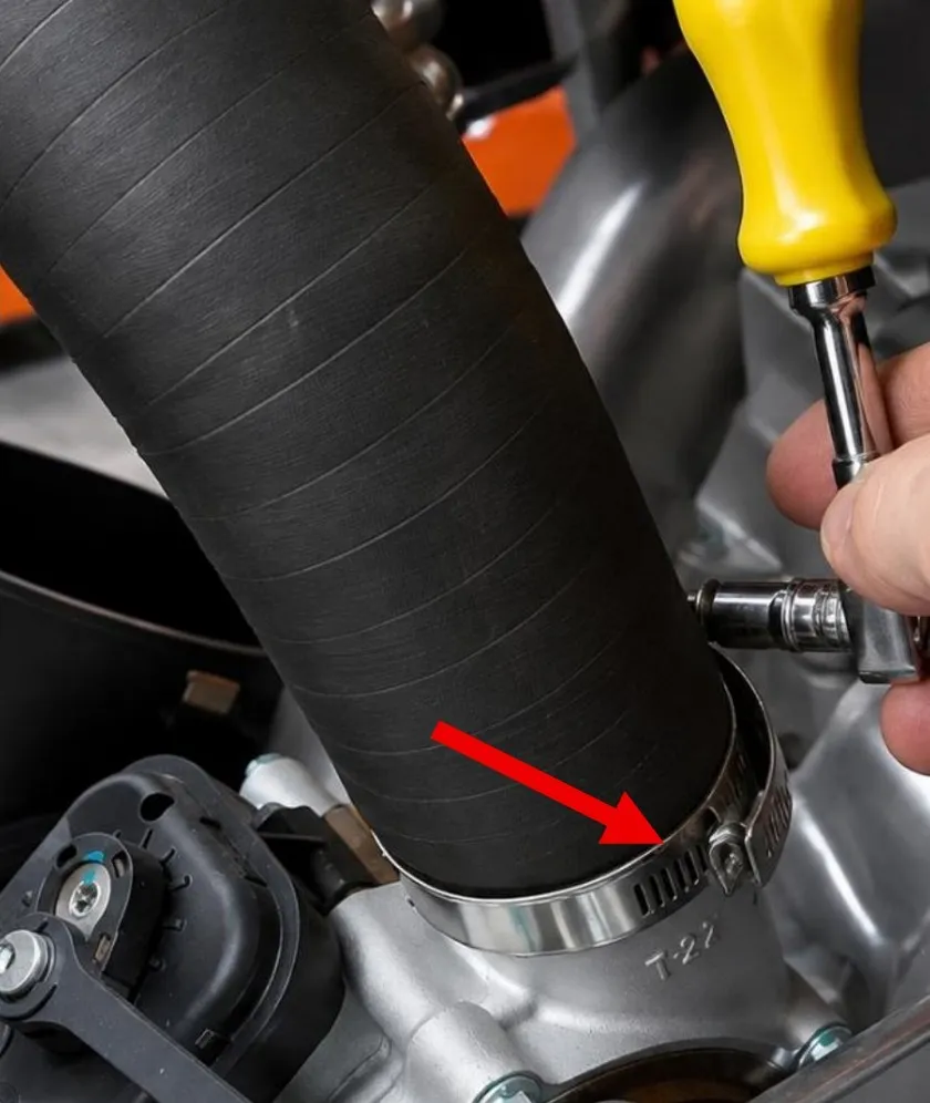
- Step 7
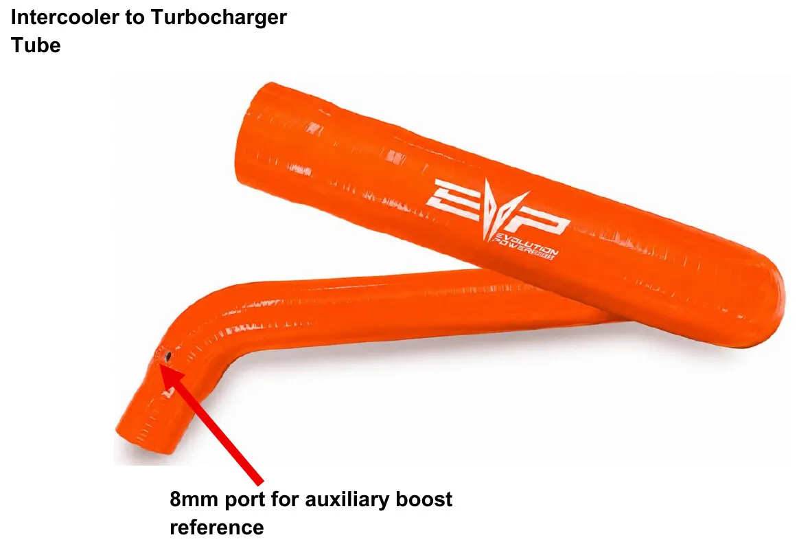
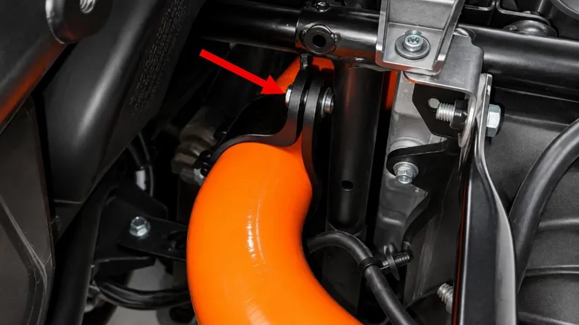
Remove both worm drive clamps from the aluminum adaptor to the intercooler. Remove the second half of the charge tube going to the intercooler. Remove the aluminum adaptor but keep the M8 flange head screw. Gather the correct clamps and support bracket for the new intercooler to turbocharger silicone. Install charge tube in reverse order without the aluminum adaptor. Mount the new support bracket using factory bolt. If you’re not using the boost reference port, plug it with supplied plug and pinch clamp.
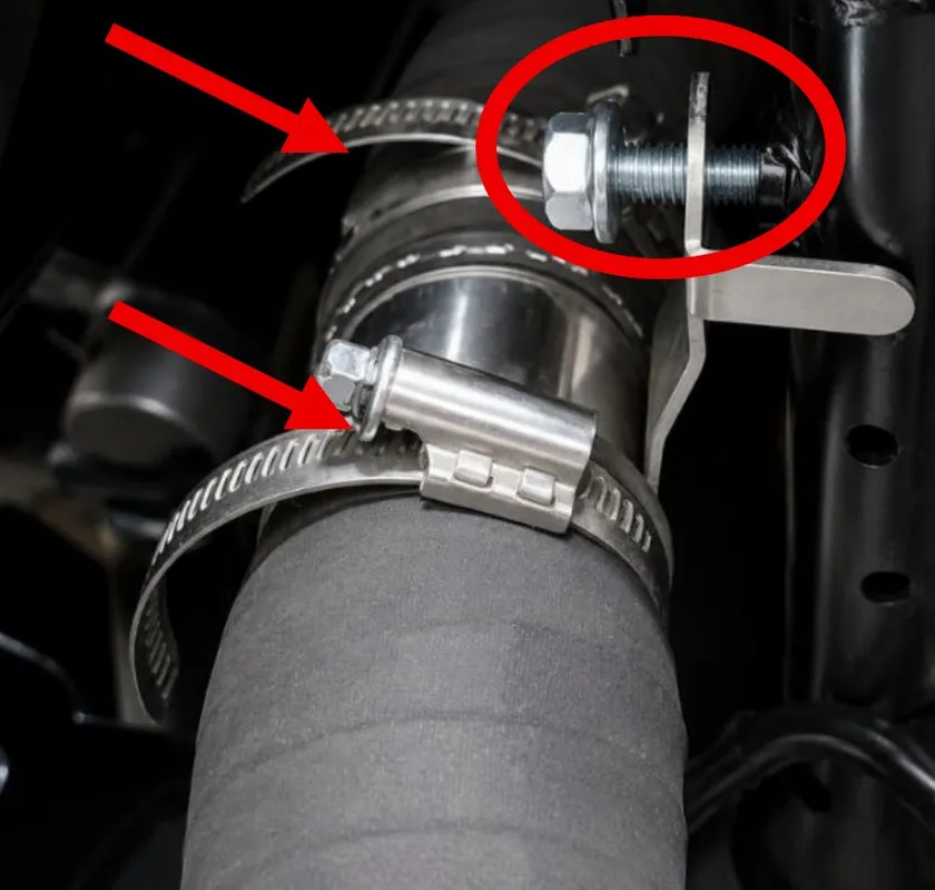
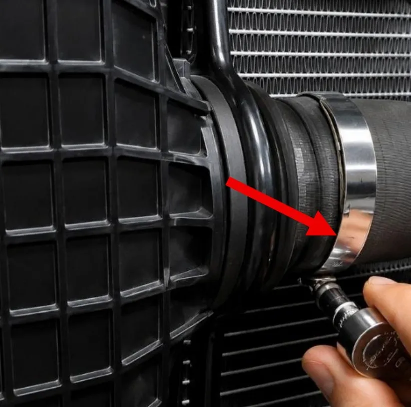
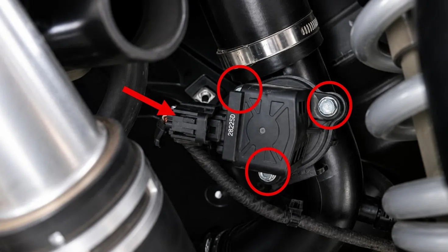
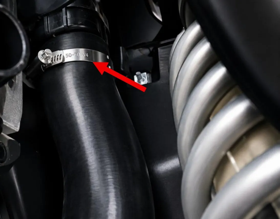
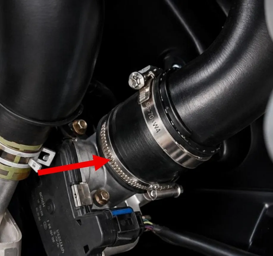
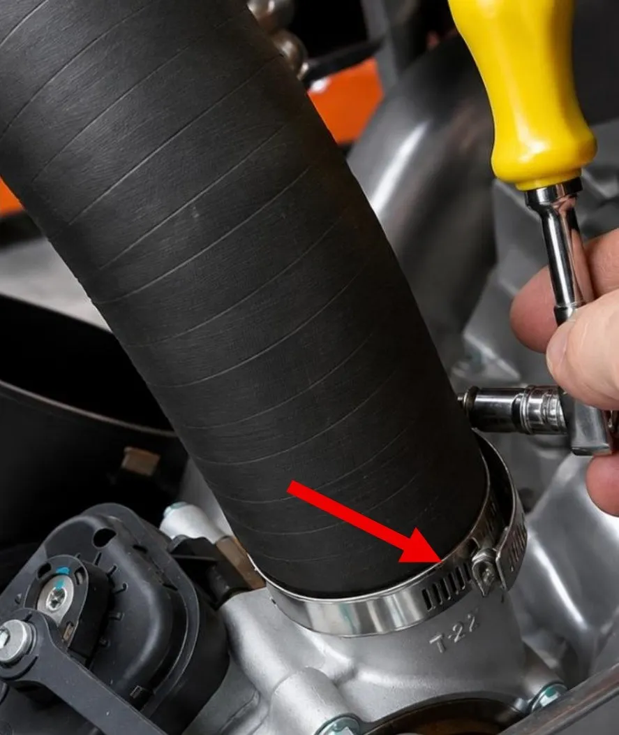
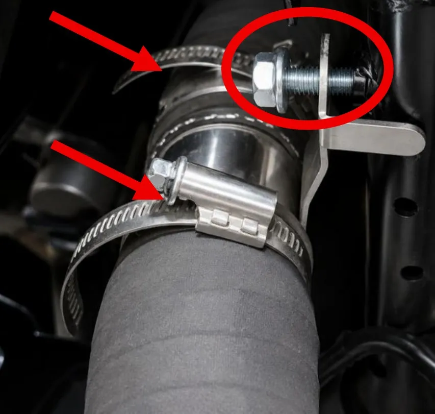
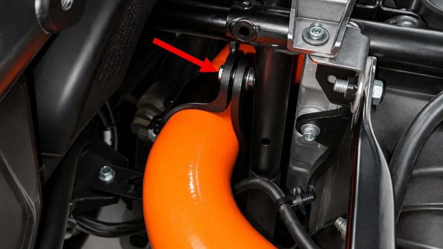
- Step 8
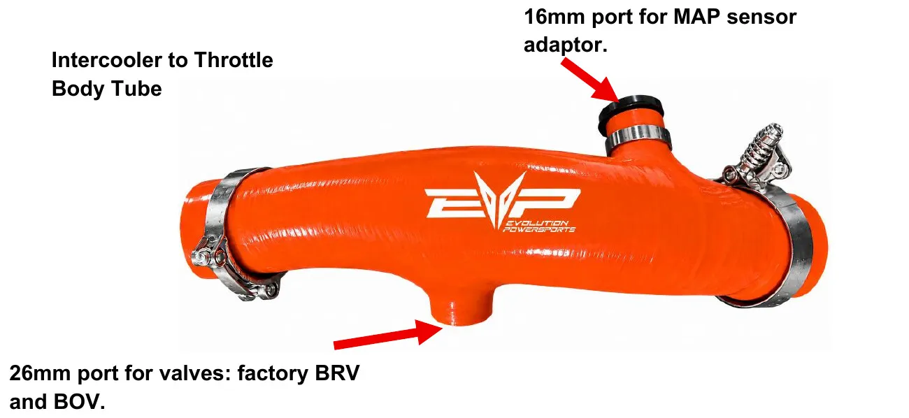
Gather the correct clamps and hardware for the intercooler to throttle body charge tube. Install the MAP sensor adapter into the 16mm port and fasten down with supplied pinch clamp. Install the MAP sensor onto the adaptor using OEM hardware. Depending on what valve you choose, install into the 26mm port and fasten with worm drive.
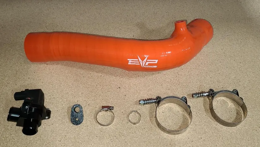
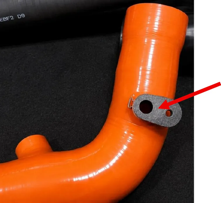
MAP sensor adaptor installed. Use dielectric grease on sensor O-ring. Fasten down with OEM hardware. - Step 9
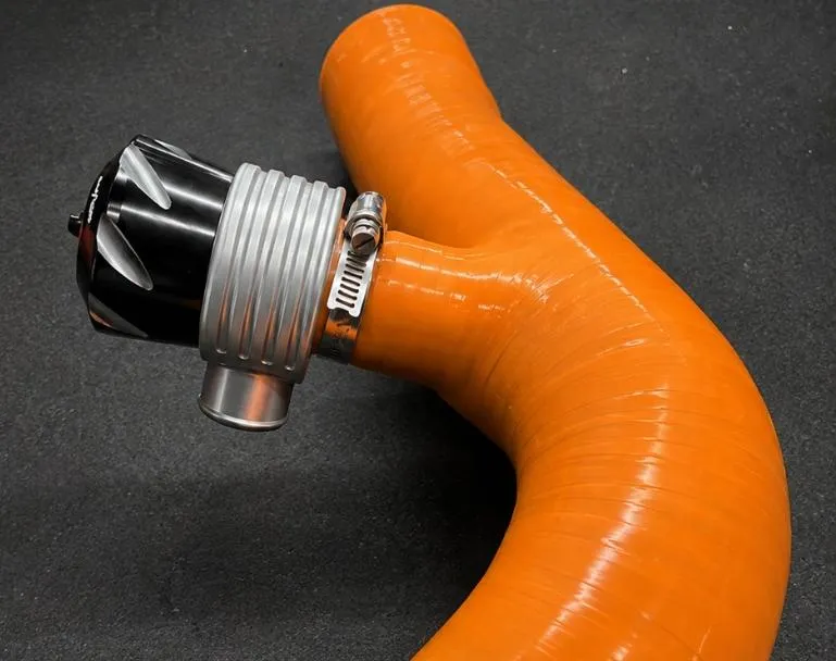
If reusing the factory BRV, mount the factory BRV to the supplied adaptor using factory hardware. Factory valve will plug into the harness and work as normal and will come with the correct return hose for factory or EVP intakes. If using a EVP mechanical BRV/BOV install the valve directly into the charge tube and fasten down with worm drive clamp. A plug-n-play connector will come with EVP valves to connect to the factory harness.
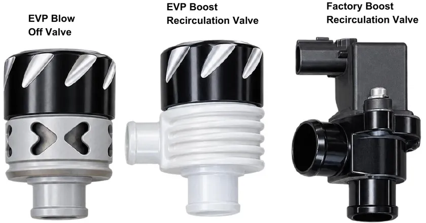
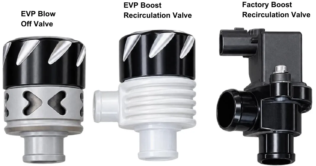
If you’re using the factory BRV install the valve onto the charge tube and install the charge tube. Reconnect the BRV to the harness and install the boost return hose. If you are installing an EVP valve following these instructions.
- Step 10
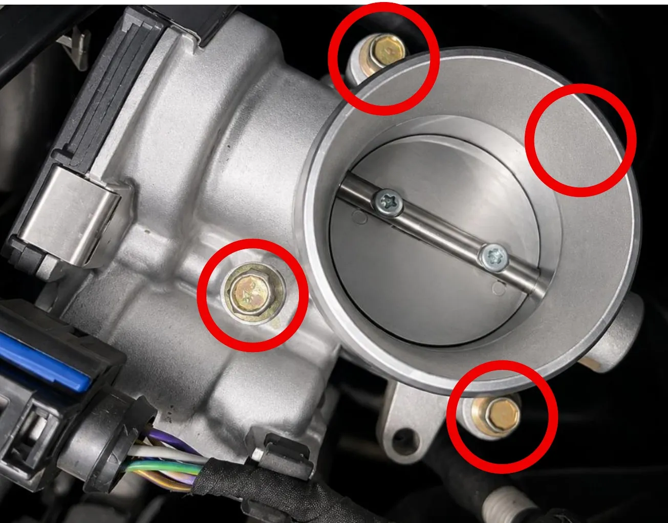
Unplug the throttle body harness from the throttle body and remove (4) 8mm bolts holding throttle body to intake manifold.
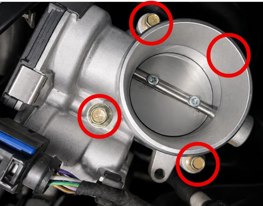
- Step 11
Install large O-ring into the groove on the throttle body spacer. Install the 90-degree barb with a thread tape. Barb will face left (towards the rear of the vehicle when installed.)
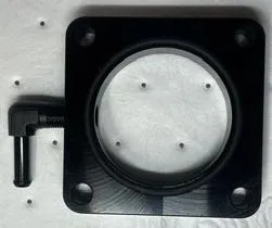
- Step 12
Remove throttle body. Confirm green O-ring is still in place on the intake manifold. Install the spacer between throttle body and plenum, use supplied bolts and install the throttle body. Make sure the barb is on top.
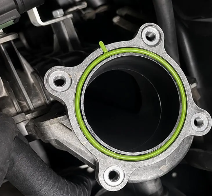
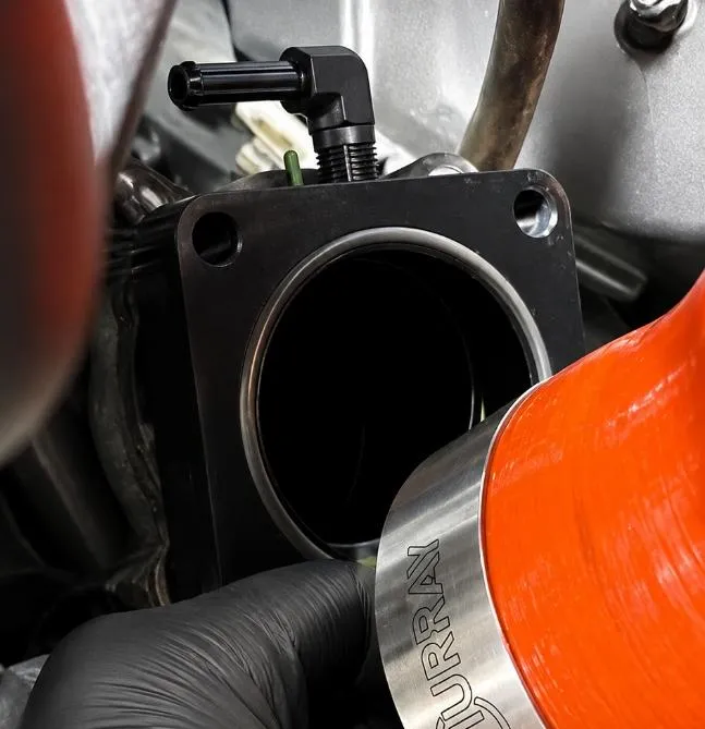
- Step 13
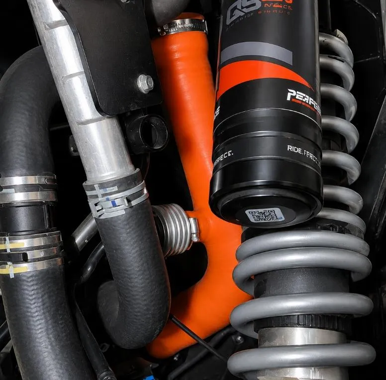
Install the mechanical BOV or BRV into charge tube and clamp with worm drive. Install the charge tube between the intercooler and throttle body. Install the 10.0” of 3mm hose to BOV or BRV and the 3.0” of 6mm hose to the 90-degree throttle body port adaptor. Fasten hose down with 11.3mm pinch clamp on the valve and 13.3mm clamp on throttle body spacer.
- Step 14
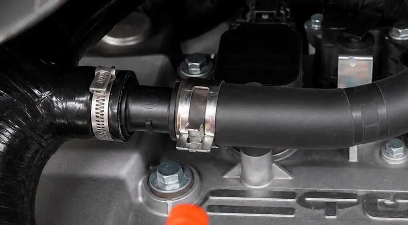
If running a factory BRV with factory intake tube you will receive a recirculation hose with a 1.0” end and 3/4" end. The 1.0” side will connect to the BRV and the 3/4" will connect to the factory intake. If running an EVP intake you will receive a recirculation hose with 1.0” on both ends. Connect the hose between the valve and intake tube.

Need technical support?
Submit a ticket with your vehicle and what you're seeing, and our support team will get back to you.
