 BUY NOW, PAY LATER. Starting at 0% APR


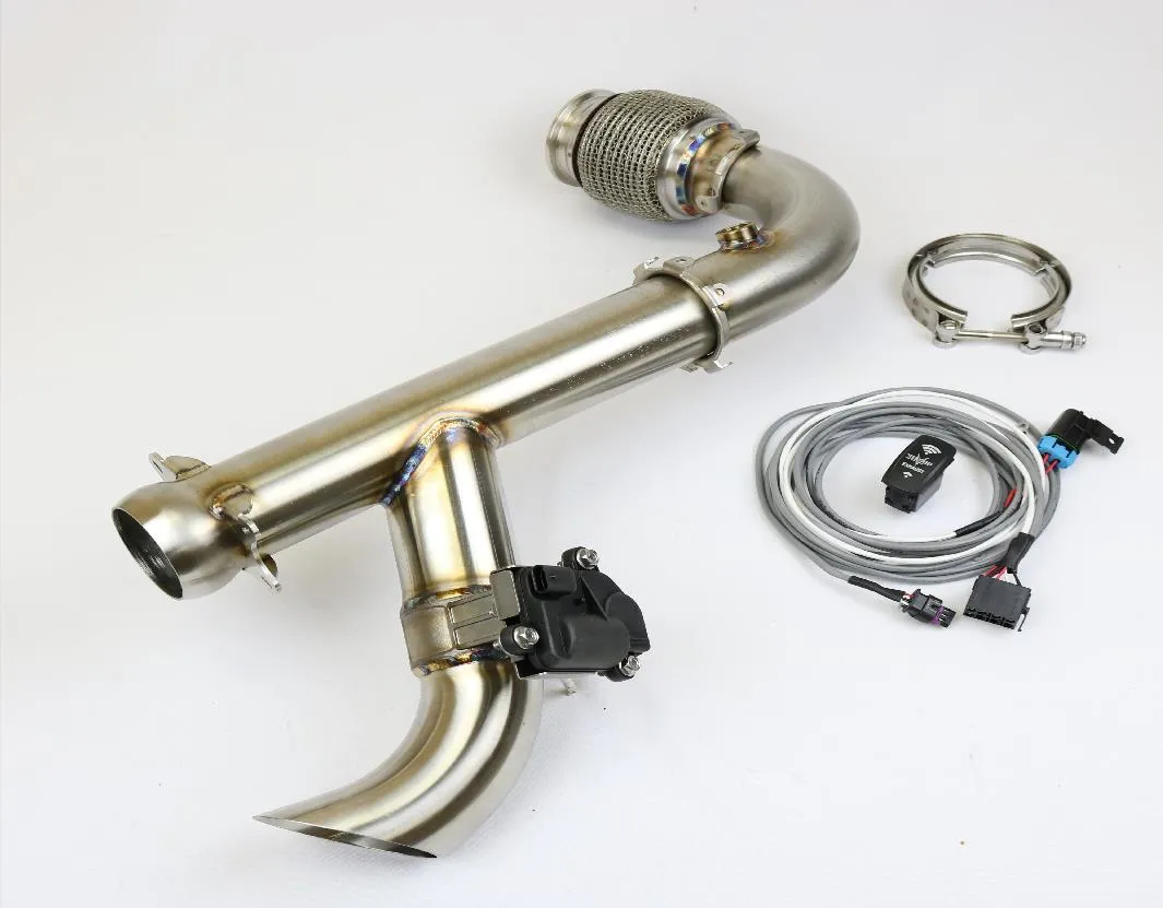
Can Am X3 “Shocker” Electric Side Dump Race Bypass Pipe
Can Am X3 “Shocker” Electric Side Dump Race Bypass Pipe
In the box
Parts and tools
Included parts
- 1Shocker Side Dump Race Bypass Pipe
- 1Wiring Harness
- 10Zip Ties
Required tools
- High Temp Anti-Seize
- 17mm Open End Wrench
- Spring Puller
- T30 Torx
- Side Cutter
- 10mm Socket
Procedure
Installation
- Step 1
Remove the rear valance by removing (5) T30 Torx bolts. (3) on the top and (2) on the bottom.
- Step 2
Remove the (4) muffler springs and (4) mounting bolts. (Figures 1-3)
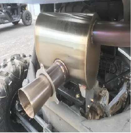
Figure 1 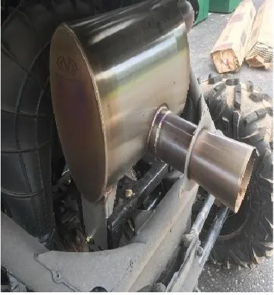
Figure 2 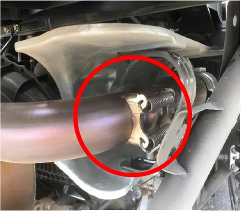
Figure 3 - Step 3
Locate and disconnect the 02-sensor wire from the wire harness.
- Step 4
Remove the 02 sensor (22mm wrench) from the exhaust pipe. Pay close attention to the tip of the sensor to prevent damage or contamination.
- Step 5
Remove the two heat shield panels and clamps (8mm socket) from the exhaust. These will be reinstalled later.
- Step 6
Loosen the v-band clamp (11mm socket) connecting the exhaust to the turbo. This clamp can be accessed through the access panel in the cabin of the car. (Figure 4)

Figure 4 - Step 7
To remove the exhaust pipe, slide it toward the front of the car, over the mount. Next, pivot the turbo side down until it is vertical. Finally, twist the entire exhaust pipe out of the shielding and remove from the vehicle. Follow the images below.
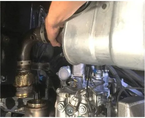
Figure 5 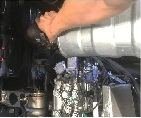
Figure 6 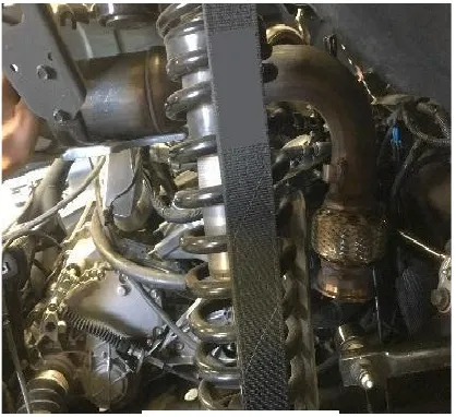
Figure 7 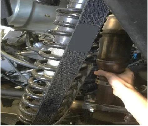
Figure 8 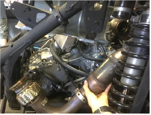
Figure 9 NoteThese images were taken with the rear cargo rack removed for better visual instruction, the rack can be left on when removing the exhaust. (Figure 4-9)
- Step 8
Insert the shocker pipe (following the removal steps) loosely secure the v-band clamp, attaching the shocker exhaust to the turbo with the exhaust gasket in place. Place anti-seize to the clamp nut.
- Step 9
Attach the heat shield panels.
- Step 10
Install the 02 sensor into the shocker exhaust with high temp anti-seize applied to the threads.
- Step 11
Reinstall the muffler and loosely mount using the (4) OEM bolts (13mm socket). Secure the muffler to the shocker with the (4) OEM springs.
- Step 12
With the springs installed and all other mounts loosely in place, tighten the V-band clamp to 8 ft/lbs (97 in/lbs). Next tighten the heat shield clamps and muffler mounting hardware.
- Step 13
Attach the rear valance with the OEM (5) T30 Torx bolts.
Procedure
Electrical Installation
- Step 1
Select an unused rocker switch position on your dash and remove the cover plate. Route the rocker switch plug attached to the harness to that location and connect the rocker switch.
- Step 2
Remove the passenger seat from the vehicle. (18mm socket, 13mm socket, 13mm wrench)
- Step 3
To gain access to the power accessory bar. Remove the left-hand lateral console panel. (Figure 1)
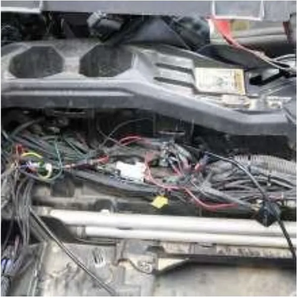
Figure 1 - Step 4
Route the wiring harness to the power accessory bar and connect the positive ring terminal to key power and the negative ring terminal to the negative terminal. (Figure 2)
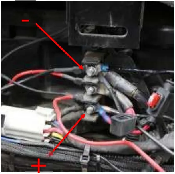
Figure 2 - Step 5
Route the remaining side of the harness back to the actuator on the exhaust. Use the supplied cable ties to loosely secure the harness to the chassis, be sure to secure the harness away from hot and or moving components.
Need technical support?
Submit a ticket with your vehicle and what you're seeing, and our support team will get back to you.
