 BUY NOW, PAY LATER. Starting at 0% APR


Can-Am Can Am Defender HD11 Shift-Tek Trail Weight Kit
Installation instructions for the Can Am Defender HD11 Shift-Tek Trail Weight Kit on the Can-Am Defender (SKU 2262010032). Parts, tools, and full procedure.
Before you start
HD11 Naturally Aspirated Trail Weights
| Performance Trail/Cruising | Cruising/Utility | Performance | |
|---|---|---|---|
| Horsepower | Stock/Tuned | Stock/Tuned | Stock/Tuned |
| Primary Spring | Stock | Stock | Stock |
| Engagement RPM | 1900 | 1650 | 1900 |
| Operating RPM | 7200 | 6800-7000 | 7500 |
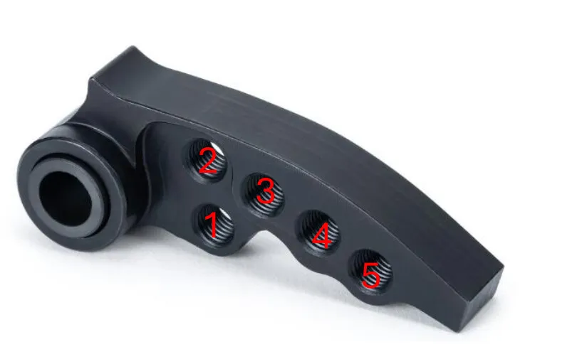
| Hole 1 | 0 | 2-3/16” Set Screw | 0 |
| Hole 2 | 2-1/4” Socket Head | 2-1/4” Socket Head | 0 |
| Hole 3 | 2-3/8” Set Screw | 2-1/4” Set Screw | 0 |
| Hole 4 | 2-3/8” Set Screw | 2-3/8” Set Screw | 0 |
| Hole 5 | 2-3/8” Set Screw | 2-3/8” Set Screw | 0 |
| Secondary Spring | Stock | Stock | Stock |
| Helix | Stock | Stock | Stock |
| Hole on Helix Cap | Stock | Stock | Stock |
| Helix Cap Clocking | Stock | Stock | Stock |
Always install a set screw on both sides of the weight arm. Install the screws with the provided thread locker, making sure the screws are installed with an equal amount of thread engagement.
2 Door DT-200 Trail Weights
| 2 Door | 2 Door | 2 Door | |
|---|---|---|---|
| Horsepower | Stage 91 Turbo | Stage 100 Turbo | Stage E85 Turbo |
| Primary Spring | Stock | Stock | Stock |
| Engagement RPM | 1700 | 1700 | 1700 |
| Operating RPM | 7300 | 7700 | 8000 |
| Hole 1 | 2-3/16” Set Screw | 2-3/16” Set Screw | 2-3/16” Set Screw |
| Hole 2 | 2-1/2” Socket Head | 2-1/2” Socket Head | 2-1/2” Socket Head |
| Hole 3 | 2-3/8” Set Screw | 2-3/8” Set Screw | 2-3/8” Set Screw |
| Hole 4 | 2-3/8” Set Screw | 2-3/8” Set Screw | 2-3/8” Set Screw |
| Hole 5 | 2-3/8” Set Screw | 2-3/8” Set Screw | 2-3/8” Set Screw |
| Secondary Spring | Stock | Stock | Stock |
| Helix | 41-52 | 41-52 | 41-52 |
| Hole on Helix Cap | Hole 4 | Hole 4 | Hole 4 |
| Helix Cap Clocking | +1 from 0 | +1 from 0 | +1 from 0 |
Always install a set screw on both sides of the weight arm. Install the screws with the provided thread locker, making sure the screws are installed with an equal amount of thread engagement.
4 Door DT-200 Trail Weights
| 4 Door | 4 Door | 4 Door | |
|---|---|---|---|
| Horsepower | Stage 91 Turbo | Stage 100 Turbo | Stage E85 Turbo |
| Primary Spring | Stock | Stock | Stock |
| Engagement RPM | 1700 | 1700 | 1700 |
| Operating RPM | 7300 | 7700 | 8000 |
| Hole 1 | 2-3/16” Set Screw | 2-3/16” Set Screw | 2-3/16” Set Screw |
| Hole 2 | 2-1/2” Socket Head | 2-1/2” Socket Head | 2-1/2” Socket Head |
| Hole 3 | 2-3/8” Set Screw | 2-3/8” Set Screw | 2-3/8” Set Screw |
| Hole 4 | 2-3/8” Set Screw | 2-3/8” Set Screw | 2-3/8” Set Screw |
| Hole 5 | 2-3/8” Set Screw | 2-3/8” Set Screw | 2-3/8” Set Screw |
| Secondary Spring | Stock | Stock | Stock |
| Helix | 35-40 | 35-40 | 35-40 |
| Hole on Helix Cap | Hole 4 | Hole 4 | Hole 4 |
| Helix Cap Clocking | 0 | 0 | 0 |
Always install a set screw on both sides of the weight arm. Install the screws with the provided thread locker, making sure the screws are installed with an equal amount of thread engagement.
In the box
Parts and tools
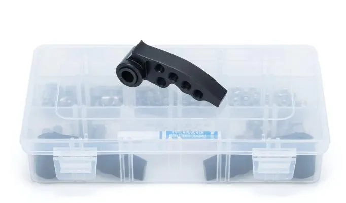
Included parts
- Weight Kit Assembly
Required tools
- P-Drive Clutch Service Tools
- 6mm Allen Socket
- 19,22mm Sockets
- Impact Driver
- T-20 Torx Socket
- Blue Loctite
- Torque Wrench
Procedure
Removing and Installing Weights
- Step 1
Remove the primary clutch from the crankshaft. Remove the airbox and clutch cover. Remove the primary clutch bolt using a 22mm socket. Install the Can-Am clutch puller (875FC0001) using an impact and 19mm socket. You will hear it “POP” off the crank.
- Step 2
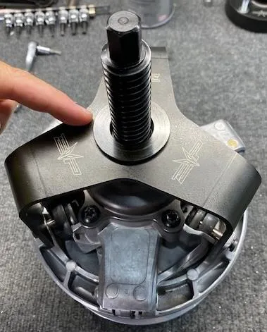
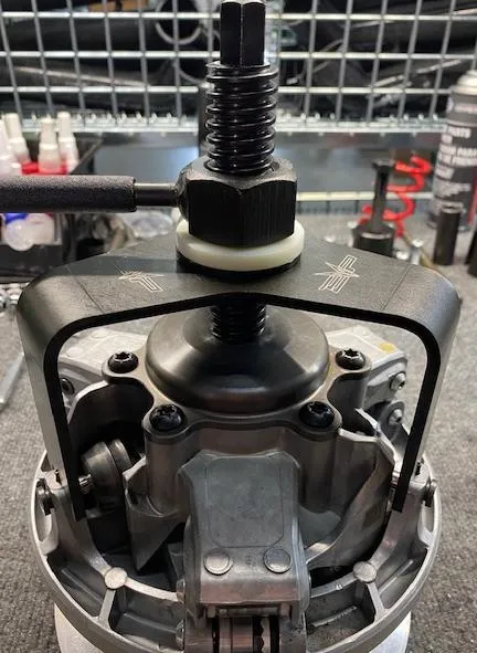
Apply some grease to the threads on tools Can Am Primary Clutch Threaded Rod & Handle for Threaded Rod. Thread tool Can Am Primary Clutch Threaded Rod into the clutch until it bottoms out on the governor cup. Install the 3 Arm Primary Compressor Tool onto the towers of the moveable sheave. Install the 1/4" Nylon Bushing into the 3-Arm Primary Compressor Tool. Compress it with the Handle for Threaded Rod.
 Note
Compress the moveable sheave far enough making it possible to remove the weights.
- Step 3
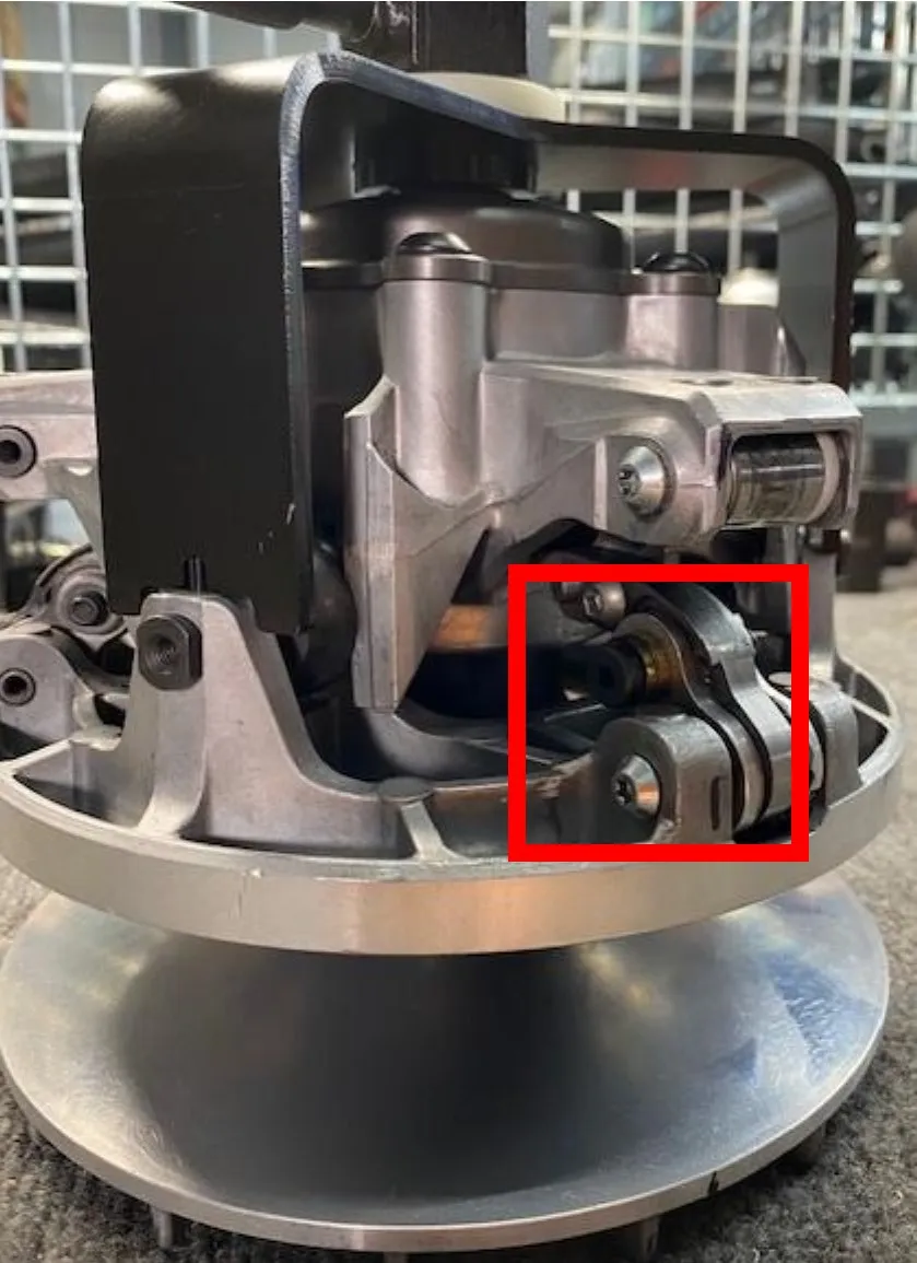
With a T25 socket remove the screws highlighted in the red box.
- Step 4
Once the screw is removed, thread in Axle Removal Tool from the left side-in. The left side castings are tapered where the axle seats. Hit the Axle Removal Tool with a hammer. Once the axle is past the taper, it will freely pull out. Remove the weight and install the new weights (See figure 4)
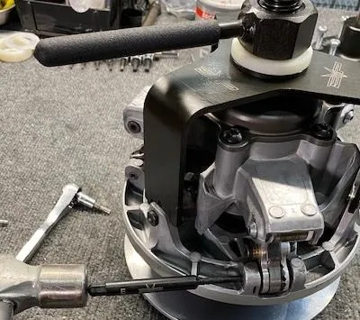
Fig. 4 - Step 5
Installation will be in reverse order. Slide the axles in from the right side to left. Install the T25 screws and torque to 4 ft-lbs. When tightening the T25 screw, it will pull the axle into the taper. Use a medium thread locker on the T25 screws. Once complete, loosen the handle on the threaded rod and remove all tools from the clutch.
- Step 6
Clean the crankshaft post and clutch with brake cleaner. Install the clutch and torque clutch bolt to 89 ft lbs.
Need technical support?
Submit a ticket with your vehicle and what you're seeing, and our support team will get back to you.
