Defender HD11 Catch Can

Defender HD11 Catch Can

Revision
REV_060526

In the box

Parts and tools

Defender HD11 Catch Can

Included parts

  • 1Catch Can Assembly
  • 1Defender HD11 Bracket Assy
  • 1Drain Hose Kit

Required tools

  • Pinch clamp tool
  • Screwdriver(s)
  • T-25 Torx
  • Hose cutter

Procedure

Installation

  1. Step 1

    Mount the catch can bracket to firewall using the supplied (3) 5.0mm x 20mm plastic black screws.

    Mount the catch can bracket to firewall using the supplied (3) 5.0mm x 20mm plastic black screws.
    Mount the catch can bracket to firewall using the supplied (3) 5.0mm x 20mm plastic black screws.
  2. Step 2

    Mount catch can to the bracket using supplied M8x16mm screws.

    Mount catch can to the bracket using supplied M8x16mm screws.
  3. Step 3

    Attach a 6” piece of 1/4” fuel hose and a 28” piece to the ball valve using 13/3mm pinch clamps.

    Attach a 6” piece of 1/4” fuel hose and a 28” piece to the ball valve using 13/3mm pinch clamps.
    Attach a 6” piece of 1/4” fuel hose and a 28” piece to the ball valve using 13/3mm pinch clamps.
  4. Step 4

    Using a zip tie, fix the ball valve to factory plastic or vent hose. Attach short end to barb on bottom of catch can, fasten with a 13.3mm pinch clamp.

    Using a zip tie, fix the ball valve to factory plastic or vent hose.
  5. Step 5

    Route the other end of the hose down and out of a drain hole in skid plate, fix to frame with zip-tie.

    Route the other end of the hose down and out of a drain hole in skid plate, fix to frame with zip-tie.
  6. Step 6

    Remove factory crank case vent hose from valve cover and place on bench, Make a mark past the 90-degree bend, 1.0” from the long section of the tube.

    Remove factory crank case vent hose from valve cover and place on bench, Make a mark past the 90-degree bend, 1.0” from the long section of the tube.
  1. Step 7

    Make a mark 1.50” from other end of the hose and cut tube at both marks.

    Make a mark 1.50” from other end of the hose and cut tube at both marks.
    Make a mark 1.50” from other end of the hose and cut tube at both marks.
  2. Step 8

    Route hose behind clutch ducting and attach 90-degree end to valve cover with worm drive, attach the other end to catch can.
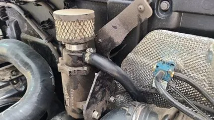
    Route hose behind clutch ducting and attach 90-degree end to valve cover with worm drive, attach the other end to catch can.
    Route hose behind clutch ducting and attach 90-degree end to valve cover with worm drive, attach the other end to catch can.
Emissions notice. This product is exempt from the emission standards and related requirements of 40 C.F.R. § 1051 as provided by 40 C.F.R. § 1051.620, and California law [e.g., vehicle code §§ 27156 and 38391]. This product is sold only for use in connection with EPA certified, purpose-built, nonroad vehicles used solely for closed course, nonroad competition/racing and not used for any recreational purpose or on public highways or right of ways maintained by and open to the public. This product is sold only in connection with machines that do not fall under state and/or federal noise or emission standards/regulations. Purchasers who/that purchase this product represent and warrant that the product is purchased only in connection with EPA-certified, emission-regulations-exempt and noise-regulations-exempt competition/racing vehicles as interpreted under applicable state and/or federal law.

Need technical support?

Submit a ticket with your vehicle and what you're seeing, and our support team will get back to you.

Contact Support
We use cookies to improve your experience on our website. Read about how we use cookies in our Privacy Policy. By browsing this website, you agree to our use of cookies. privacy policy
accept

Your cart

×
×