 BUY NOW, PAY LATER. Starting at 0% APR


Sea-Doo 800/1100 EVP Stage 2-3 TCL Delete, Motor Mount & Engine
800/1100 EVP Stage 2-3 TCL Delete, Motor Mount & Engine Bracket
Before you start
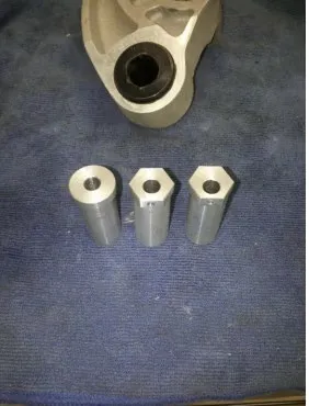
Check your belt alignment and parallelism first before teardown as it will help with what eccentric sleeve you choose the sleeves are both different one giving more than the other up for up to .035" of adjustment from 0 or center as factory for a total of .070" of movement.
In the box
Parts and tools
Required tools
- Socket Set
- Torque Bit Set
- Sawzall With Fine Blade
- Dremel
- Drill and Drill Bits
- Rivit Gun
- Alignment Tool
- Calipers
- 20 Ton Press
- Arctic Cat Jam Nut Tool
Procedure
Installation Steps:
- Step 1
Remove side panels, hood, seat and gas tank.
- Step 2
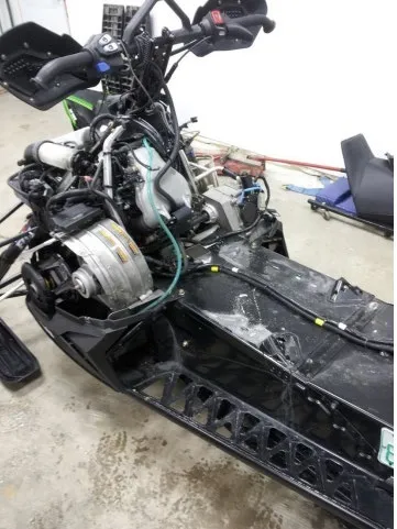
Although the job can be done by lowering the back half of the rear suspension, removing the suspension completely is ideal. Hoist the rear of the sled up so you can access the front of your tunnel.
- Step 3
Take pictures prior to moving the wiring and fuel lines to be sure you can get back to factory when completed.
- Step 4
Remove the jackshaft. See the Arctic Cat Shop manual and/or OSP’s excellent jackshaft removal/installation procedure: http://onestopperformance.com/InstallACXF1100Jackshaft.html
- Step 5
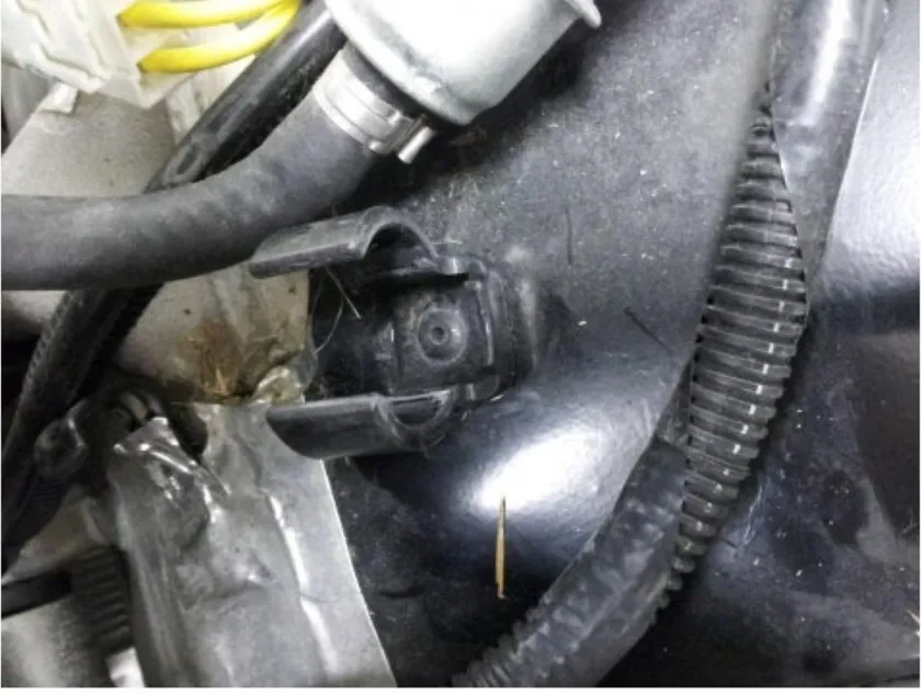
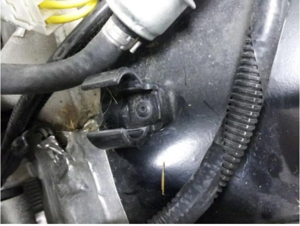
Remove fuel filter bracket. See picture.
- Step 6
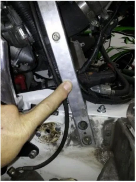
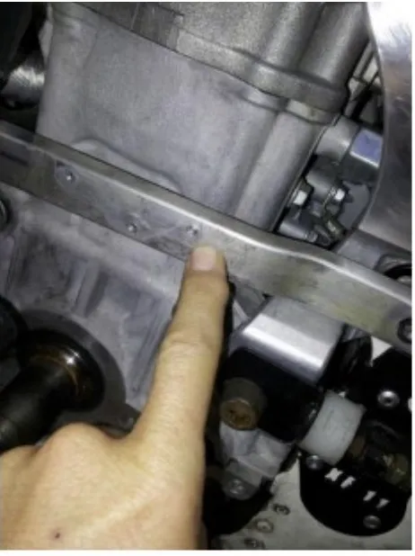
Remove factory braces in figures 1 and 2 for ease of removing factory TCL. Remove the factory TCL.
- Step 7
Move aside wiring and gas lines so you will be able to cut off the factory engine mount tabs on the factory heat exchanger.
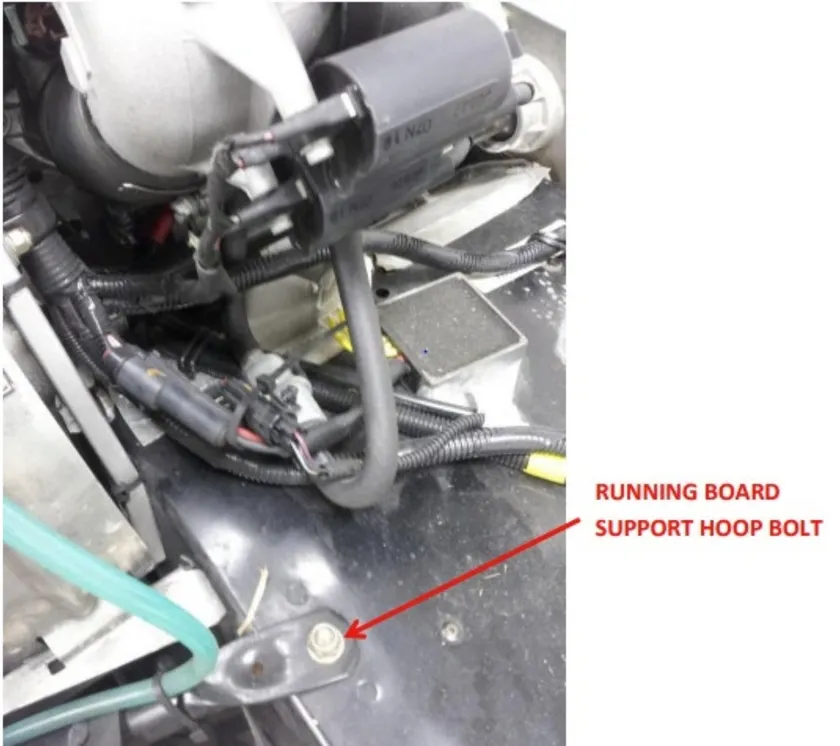
- Step 8
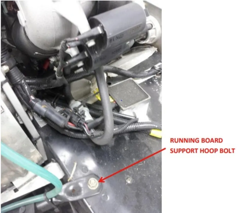
Remove the bolts holding the running board support hoops – the bolt heads for these are located above the track near the front of the tunnel. It requires a T-30 Torx socket or bit.
- Step 9
Use a block of wood to support the back of the engine. Remove the mag side motor mount bolt and remove the factory aluminum engine brace that contains the rubber mount.
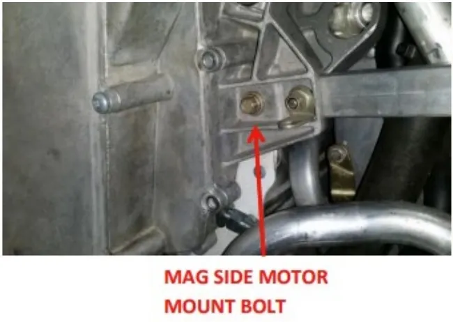
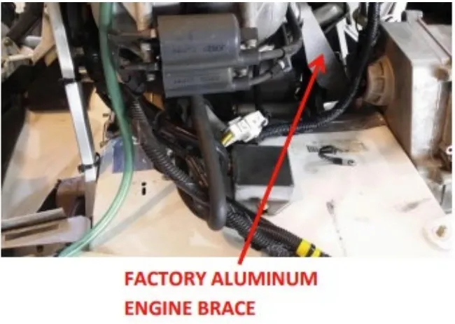
- Step 10
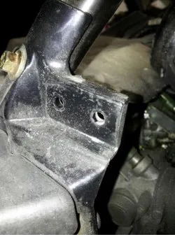
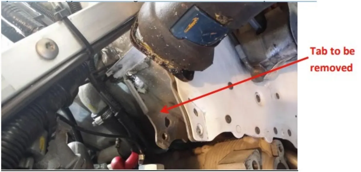
Test fit your engine support brackets – the rear bolt hole of the engine bracket should line up with the running board support hoops bolt holes (the bolts you just removed). Using the front of the Turbie/EVO engine braces as a template, draw on the factory engine mounting tabs the approximate shape of the tabs that need to be removed. You only need to remove enough of the factory tabs so the engine braces fit without interference. During the test fit, you will notice there are 2 rivet heads that will be under the engine brackets and will prevent them from sitting flush on the tunnel. Using a 3/8” drill bit, drill the head of the rivet so it is flush with the tunnel. DO NOT DRILL ALL THE WAY THROUGH – JUST ENOUGH TO MAKE THE HEAD FLUSH WITH THE TUNNEL.
- Step 11
Using the rough template drawn above, rough cut the tabs off. (A sawzall with a long blade works well). (Clutch Side Pictured) If you have a 2012, your heat exchanger tab will look different from the picture below.
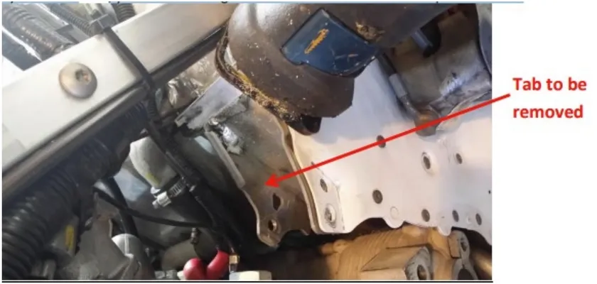
- Step 12
After the tabs have been removed, clean up you work with an air grinder or dremel – be careful not to grind or puncture the heat exchanger.
- Step 13
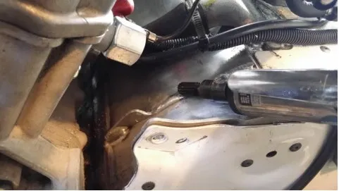
Install the Turbie/Evo engine support brackets by installing the running board support bolt through the rear hole of the bracket – the brackets are left and right and only go in one way!
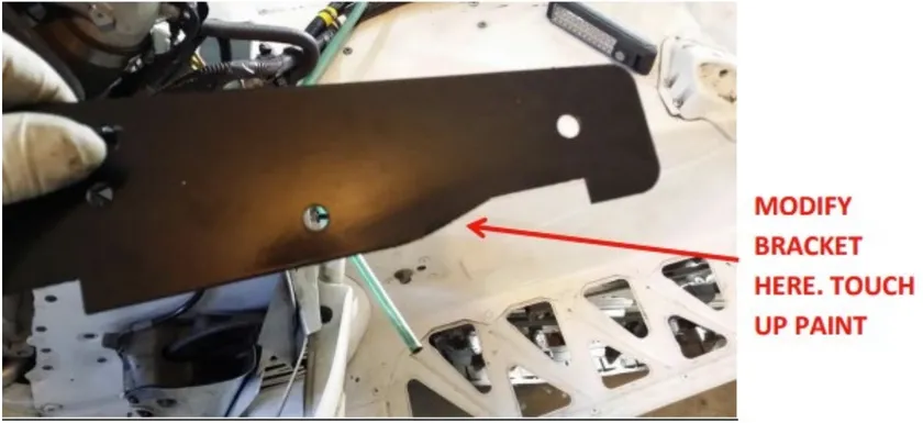
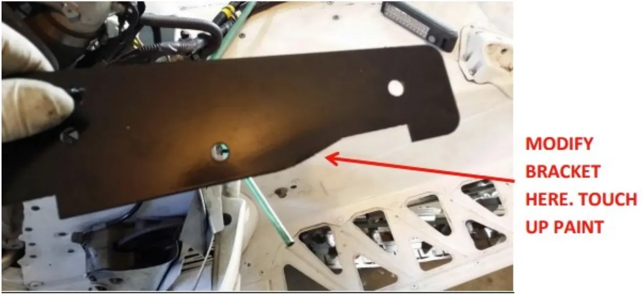
MODIFY BRACKET HERE. TOUCH UP PAINT Noteon 13 and 14 machines, the PTO side Turbie/EVO bracket may need to be modified slightly to clear the footwell aluminum. See picture below.
- Step 14
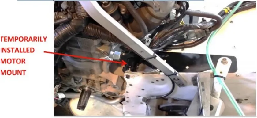
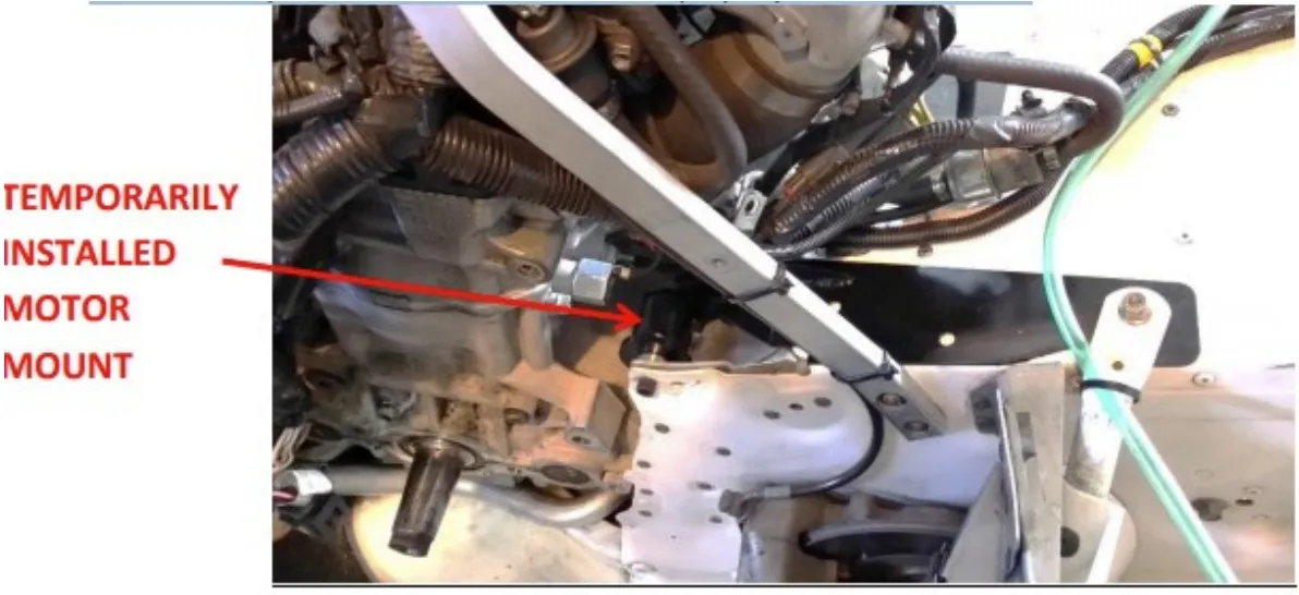
In order to make sure the brackets are installed correctly, tighten the rear running board support bolt. Temporarily Install the Turbie/Evo rubber motor mounts with the straight aluminum sleeves on both the PTO and Mag sides. Lightly tighten bolts. With the motor mounts temporarily installed, use the front two holes of the engine support brackets as a template and drill the holes with a 5/16 drill bit. An auto body type right angle air drill with a short bit is very helpful for the pto side. If this tool is not available, you may have to remove the rubber intake plenum boot on the PTO side to properly drill the front hole.
- Step 15
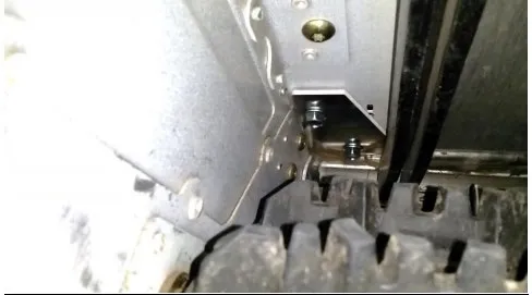
Install the doublers on the underside of the tunnel with the supplied 5/16 x ¾” flange head bolts – Line up the holes you drilled in step 14 with the holes on the doubler plates. The bolt heads must be through bolted from the bottom! Secure the engine braces using the 5/16” serrated flange nuts. Apply green Locktite to the top of the threads protruding through the nut.
- Step 16
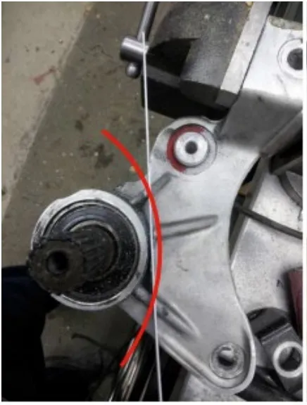
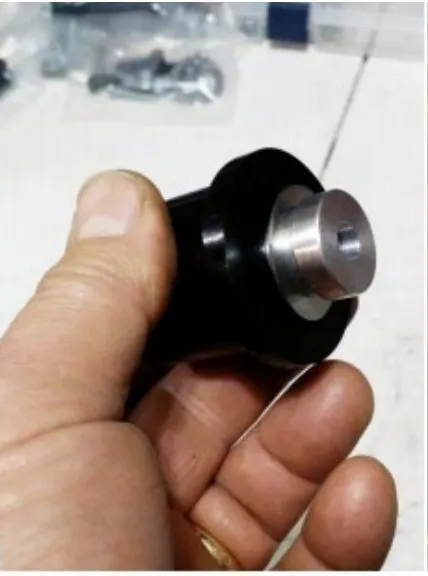
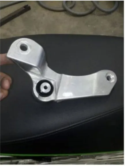
Modify the old TCL so it will be now just become a motor mount (Figures 4 & 6)
- Step 17
After your TCL has been modified, install the new Turbie/Evo polyurethane motor mount. Install the STRAIGHT aluminum sleeve toward the outside of the TCL (Figure 6) – use a supplied washer between the rubber mount and the aluminum sleeve – see Figure 5 above.
- Step 18
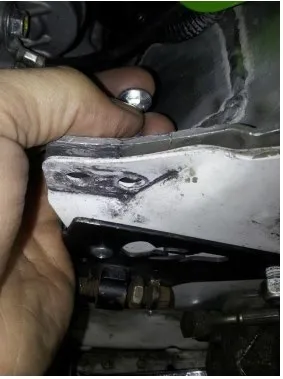
Install the supplied ¼-20 carriage bolt supplied with the kit into the hole just behind the motor mount hole on the PTO side.
- Step 19
Drill out the PTO side upper shock tower holes and sensor mount attachment holes to 5/16" (Figure 8.) to accept the new hardware.
- Step 20
Install the modified factory TCL with motor mount and sleeve installed. Reinstall the engine bolts that hold it in place. Next, test fit the Turbie/EVO TCL Delete billet aluminum bracket. Ensure there is adequate clearance around the factory TCL you just modified. If anything is touching, uninstall the factory TCL and modify further.
- Step 21
DRY INSTALL your Turbie/EVO TCL Delete Bracket.
 Caution
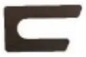
The doweled “TRAPEZOID machined piece MUST be installed into the recess of the frame between the frame and the TCL bracket. You may need to add a .050 shim to the trapezoid piece to allow the TCL bracket to be true with the plane of the jackshaft. A shim that looks like the picture below may be included in your kit depending upon the manufacture date.
- Step 22
Use the supplied 5/16” x 1” flange head bolts and serrated nuts for the shock tower, the supplied 5/16” x 3.5” socket head cap screw and nylock nut and 10mm socket head cap screw and lock nut. You may need to jack up the belly pan area to make the holes line up. The reason for this is the chassis sags substantially when the spars are removed.
- Step 23
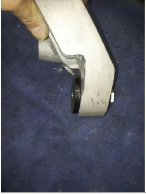
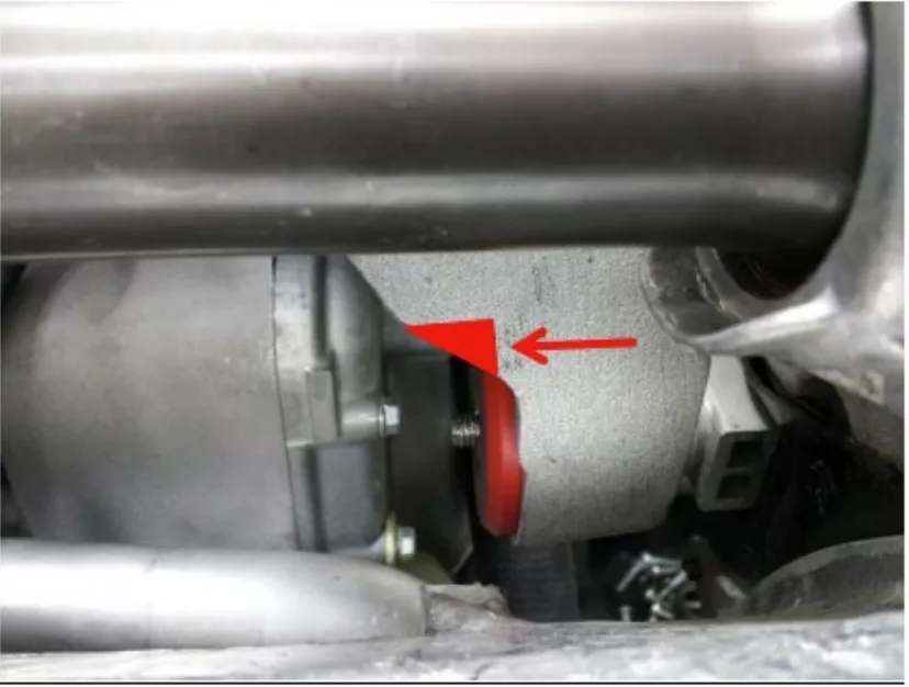
Modify the factory mag side motor aluminum engine bracket as shown to provide clearance for the Turbie/EVO engine support bracket.
- Step 24
Choose witch aluminum sleeve you will need for your application there is 2 eccentric one that gives approx. 35 tho of movement and a 70 tho of movement and one that is straight. THE ECCENTRIC SLEEVES ARE ONLY FOR THE MAG SIDE MOTOR MOUNT. Install a supplied washer between the aluminum sleeve and the polyurethane mount (see Figure 5)
- Step 25
Install your new style Turbie/Evo Mag side polyurethane motor mount. Make sure that the polyurethane flange is to the inside and the aluminum flange is to the outside. Some dish soap makes the rubber mount easier to install in the cast aluminum factory engine brackets.
- Step 26
If you are reusing the factory jackshaft, on the chain case side, reuse the factory bearing and collars as they were prior to disassembly.
- Step 27
Because of the variances from chassis to chassis, we are recommending to either reuse the factory spherical bearing from the clutch side. If using the clutch side bearing, the seals are to be removed. The straight bearing will only be used on the clutch side. The upper chain case bearing should not have seals on either side. Again see the shop manual or the OSP link provided earlier for bearing installation procedure. Make sure you do not damage the chain case seal!!!
- Step 28
DRY INSTALL the factory jackshaft or our XD jackshafts depending upon the kit. All non-stock sleds should have the jackshafts upgraded. When installing the jackshaft, it is very important to pull the jackshaft bearing shoulder ALL THE WAY AGAINST THE BEARING on the chain case side!!! This is accomplished by threading the locknut lock collar and lock nut onto the chain case side of the shaft and using the factory Arctic Cat lock nut tool to draw the jackshaft to the bearing shoulder. You can use a small impact wrench to do this. If the shaft is not tight against the bearing, this will cause the PTO bearing not to seat properly.
- Step 29
On the PTO side, check where the jackshaft bearing shoulder is in relationship to the bearing pocket of the TCL Delete bracket. Using the supplied shims, shim the bearing shoulder on the TCL Delete side so the shoulder is flush with the back of the bearing pocket on the TCL Delete. This way, once everything is installed, there will be no side to side play and there will be no side load on the bearing.
Cautionon earlier TCL Delete Brackets, the shims will not go through the hole of the TCL delete bracket. You may have to remove a slight amount of material from the bearing hole of the TCL delete bracket to make the shims fit through the hole
- Step 30
Uninstall the jackshaft and TCL delete bracket.
- Step 31
Install the correct # of shims determined in step 28 and press the supplied clutch side bearing onto the jackshaft. Be sure it is seated tightly against the shims (if any) or shoulder. Then press the shaft and bearing into the TCL Delete bearing pocket. Reinstall the factory bearing lock ring.
Noteheating the bearing pocket with a propane torch makes the bearing slide in easier
- Step 32
Install the TCL Delete Bracket and jackshaft assembly. Reinstall jackshaft as in step 27. Install the jam nut with a small impact wrench, then loosen and reinstall to 40 ft lbs. Bend a tab on the lock ring over so the jam nut does not loosen. Install all TCL, bolts and nuts – use blue Locktite on all bolts
- Step 33
Reinstall the factory or upgraded gears and chain at this time. Make sure you line up the top drive gear with the bottom gear by using a straight edge. Shim the top gear as necessary. Do not use any thin washers against the c clip on the shaft. Make sure there is at least a .050 washer in this location.
- Step 34
Re-rivet factory fuel filter clip either by drilling a new hole or by reusing the original hole and shimming it up with the three washers underneath to match the height of the Turbie/EVO engine brackets. WATCH WHERE YOU ARE DRILLING – THE HEAT EXCHAGERS ARE UNDER THE TUNNEL
- Step 35
Re-install all wiring and fuel lines back to original places and reinstall fuel tank, seat, hood and rear suspension.
Procedure
CLUTCH ALIGNMENT PROCEEDURE
- Step 1
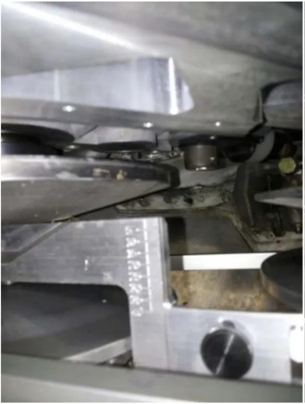
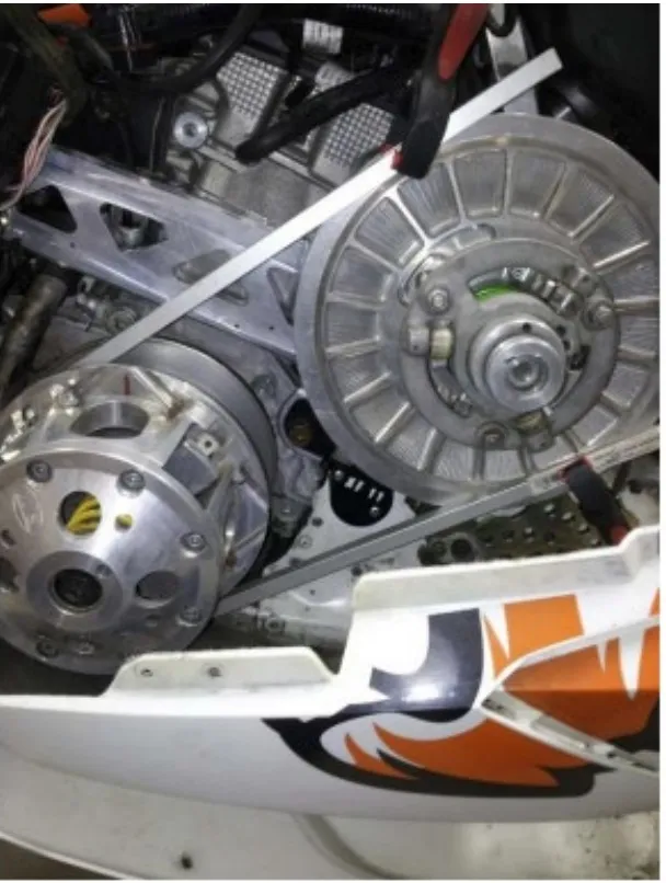
When checking motor/clutch alignment the best thing to is use the Arctic cat alignment bar or an adjustable alignment bar like the one in the pictures which is available from Team. Also, One Stop Performance has an excellent clutch alignment tool which is available from us or One Stop. Use for adjusting secondary clutch offset. (Figure 1) You can use two 1/2"X1/2"X18" aluminum bars for checking clutch parallelism and two spring clamps to hold the bars while checking and making adjustments (Figure 2)
- Step 2
For accurate measuring, the use of a small digital caliper like the one in Figure 3 works very nice for this job and can be purchased a tool store for about $20.00
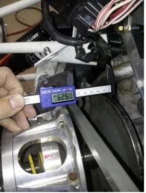
- Step 3
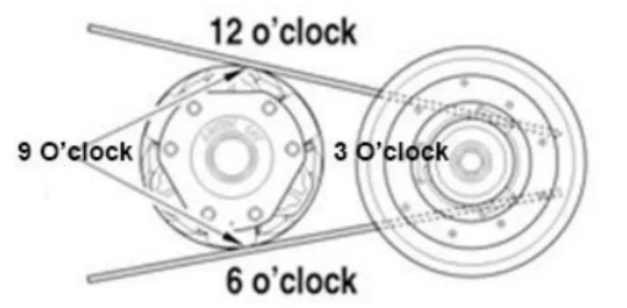
Position your alignment bar in the space between the sheaves on the primary and then clamp your 1/2 X 1/2 bars to the outer sheave of the secondary. You are now ready to start checking your measurements for parallelism (Figure 4 ). Adjustments will be made with the eccentric collar on the mag side and a short and skinny 19mm wrench. You may have to grind your wrench down to make it thin enough to fit. (Figure 5). Check for parallelism and measuring at the 12:00 and 6:00 positions on your primary clutch. Then check the parallelism at the 9:00 and 3:00 positions. With our TCL Delete installed, the measurement at the 9:00 position should have 1-1.5 mm of positive twist so that when the engine is at full power it will align itself to zero. (See Figure 7 for more clarification)
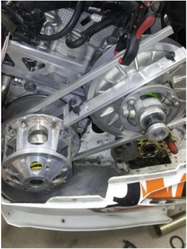
Fig. 4 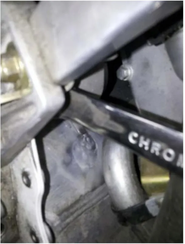
Fig. 5 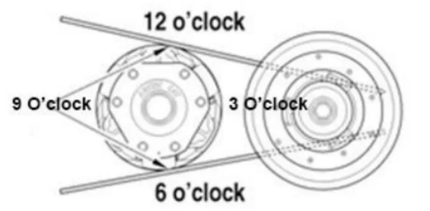
- Step 4
If you already have an OSP engine snubber, this helps to make small adjustments as well. After all the adjustments have been made and are correct tighten the rubber engine mount bolts. In order to get the parallelism correct, it may require a shim under one side or the other of the FRONT motor mount.
- Step 5
Next, check your secondary clutch offset. This can be done with the factory Arctic Cat alignment bar. Add or remove shims behind your secondary clutch to achieve the proper offset. Once the correct shims are in place and the offset is correct, re-torque your secondary clutch bolt to spec.
Need technical support?
Submit a ticket with your vehicle and what you're seeing, and our support team will get back to you.
