 BUY NOW, PAY LATER. Starting at 0% APR


2023 Can Am X3 Turbo (135hp) Intercooler Upgrade Kit
Installation instructions for the 2023 Can Am X3 Turbo (135hp) Intercooler Upgrade Kit on the 2023 Can-Am Maverick X3. Parts, tools, and full procedure.
In the box
Parts and tools
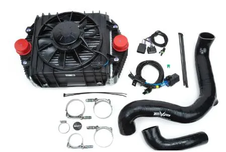
Included parts
- Intercooler with Fan Assembly
- EVP Intercooler Harness(s)
- Hardware Kit
- Charge Tube Kit
- (Optional) Big Injectors
- (Optional) Big Wastegate
Required tools
- 10,11mm Sockets
- Torx Sockets
- M6 Allen Socket
- Side Cutters
- Push Dart Tool
Procedure
Installation
- Step 1
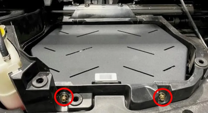
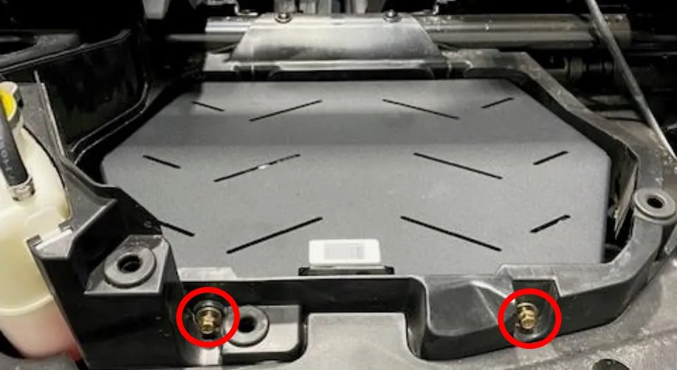
Remove the intercooler and intake plastic shrouds. Remove the intercooler blank by loosening (4) 10mm screws. (2) are located behind the turbocharger access panel.
- Step 2
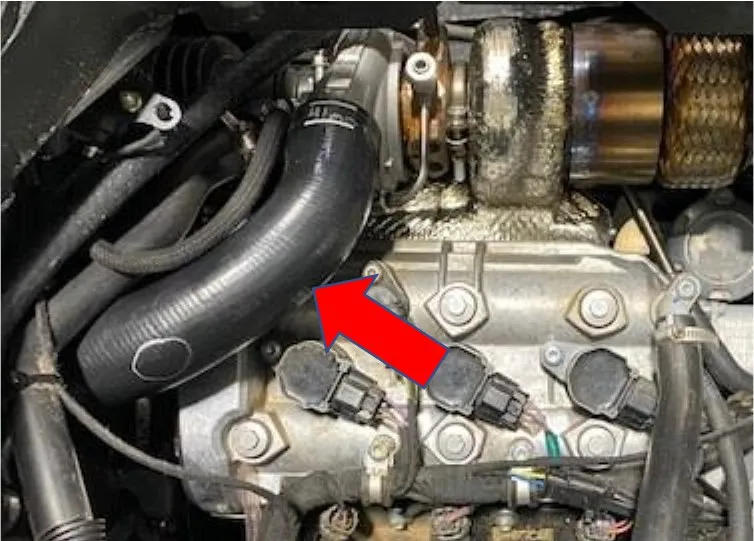
Loosen and remove the clamps securing the charge tube. Remove the charge tube from the throttle body and intercooler. It may be easier to remove some CVT duct work. This will allow more room around the throttle body.
- Step 3
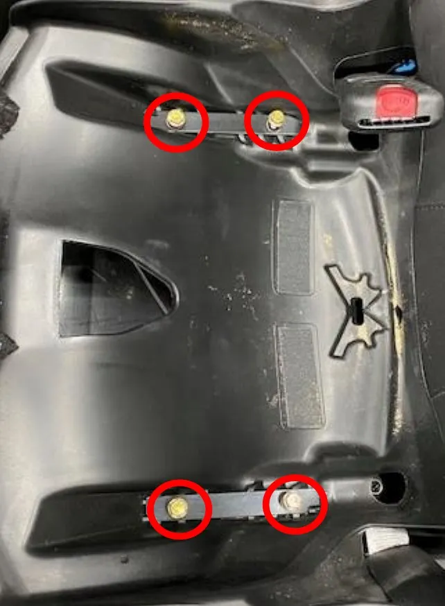
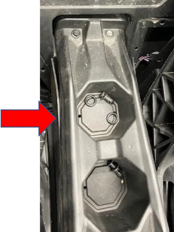
Locate the front passenger seat. Lift up the bottom seat cushion, you will find (4) screws and (2) plates. With a 13mm socket remove all (4) screws. You can now move the seat around. Next, remove the passenger side of the center counsel. You must pop (3) clips.
- Step 4
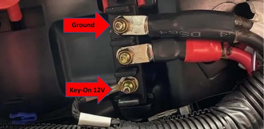
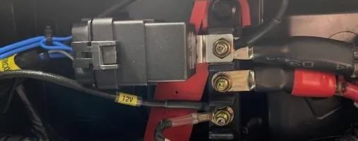
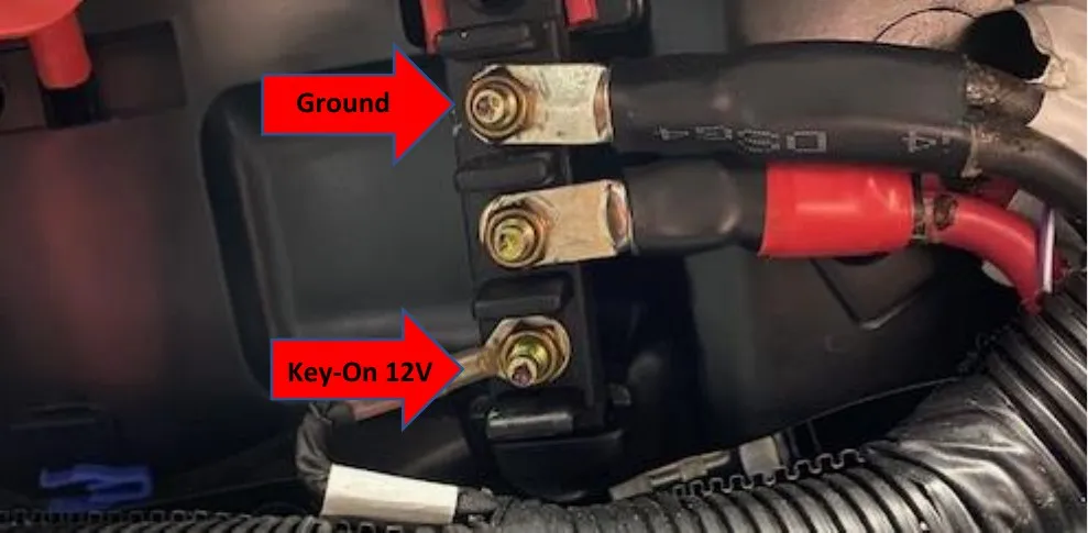
Locate the bus bar located in the middle of the center counsel. From top to bottom: Ground, 12v battery power, key on power labeled Acc_1. Mount up the supplied harness as shown below. Use a 10mm socket. You can mount the relay anywhere or mount it with the ground stud as shown below.
- Step 5
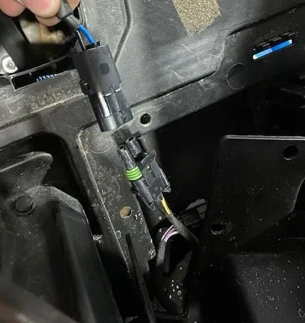
Run the 2-contact connector (for the intercooler fan) through the center console to the ECU tray. Located behind the drivers seat (rear passenger in 4 seater). Inside the ECU tray you will find the OEM intercooler 2 pin connector. Connect them. Make sure the OEM connectors are clean.
- Step 6
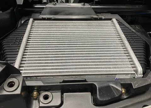
Install the charge tubes onto the vehicle. It is easier to install the upper charge tube onto the turbocharger, and lower charge tube onto the throttle body. Install the intercooler into the car. Connect both charge tubes to the intercooler and reuse the (4) 10mm screws to fasten down the intercooler. Use an 11mm socket to tighten all charge tube clamps.
- Step 7
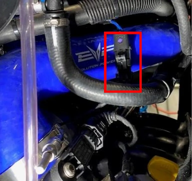
Connect the fan pigtail to the 2 pin connector on the OEM harness. It may be zip tied to the bottom of the bed.
- Step 8
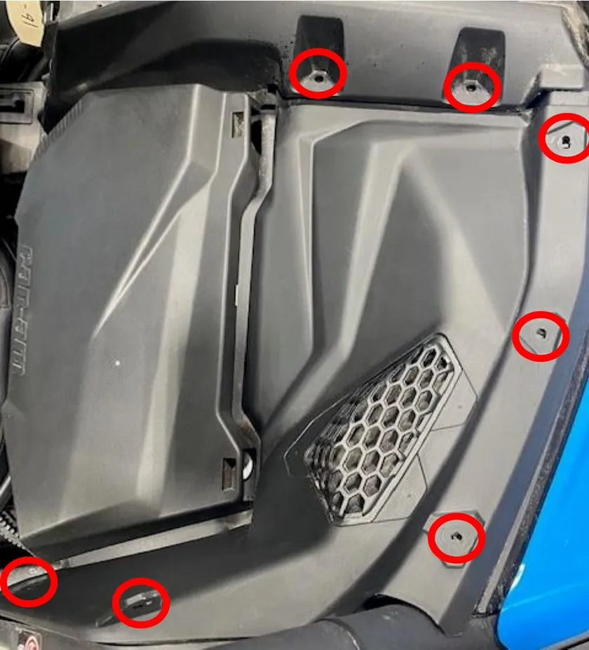
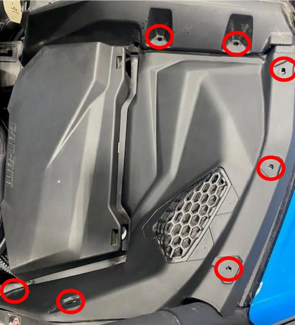
Remove the upper dash on the passenger side. There will be (2) push darts and (5) T-30 screws.
- Step 9
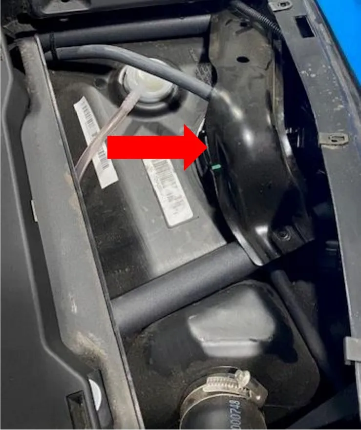
remove the fuel pump assembly bracket using a 10mm socket.
- Step 10
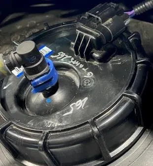
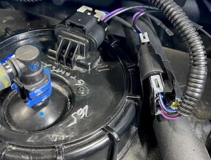
Locate the fuel pump connector, push back the grey lock and remove the connector. Install the supplied EVP fuel pump pigtail. One connector will go the OEM harness and one connector will go to the fuel pump assembly. Reinstall the grey clip on both male connectors.
- Step 11
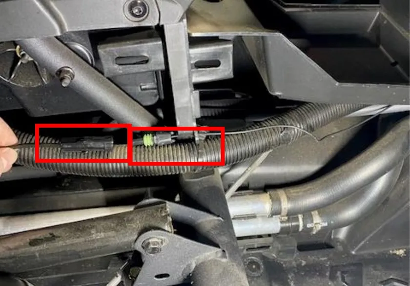
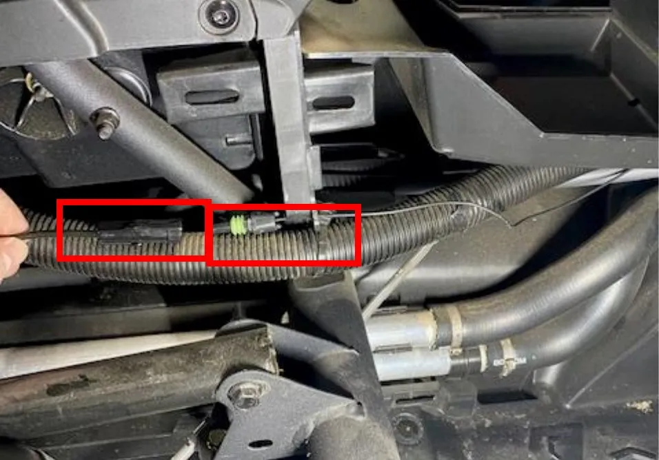
On the other end of the fuel pump harness you will find a 1 contact connector. Route that through the dash and into the cab (next to the coolant lines). Plug into the other 1 contact connector coming from the relay harness. Zip tie any excess wire.
- Step 12
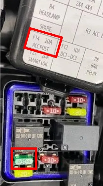
Located on the dashboard is a fuse box. Open the fuse box and remove the 20amp fuse in box F14 and replace it with the supplied 30amp fuse.
- Step 13
Zip tie any access wires underneath the center counsel. Keep wires away from heat sources. Reinstall the center counsel panel and passenger seat. Reinstall the turbocharger access panel and CVT duct work.
Procedure
Wastegate and Injector Installation
- Step 1
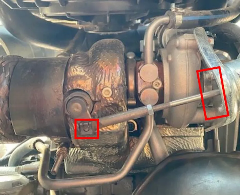
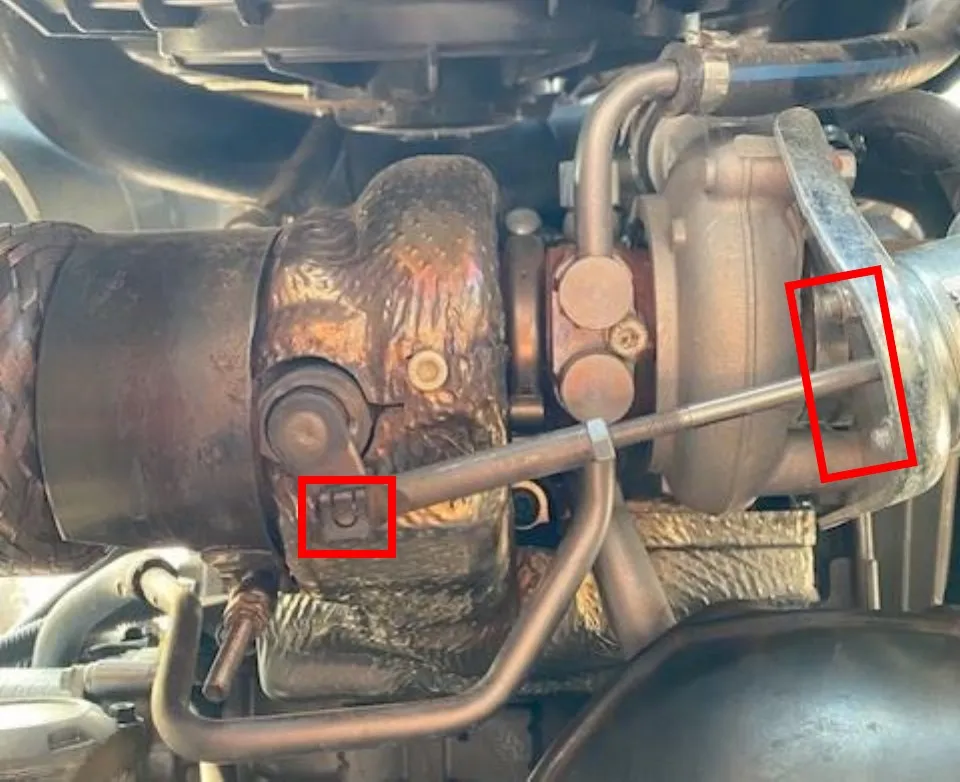
With the turbocharger access panel remove, find the wastegate. Remove the wastegate clip (be careful not to lose the clip). Remove the wastegate line and both nuts holding the wastegate to the bracket.
- Step 2
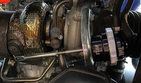
Install the new wastegate onto the OEM wastegate bracket. Set your crack pressure to your tune package. Reinstall the wastegate rod clip and vacuum line.
- Step 3
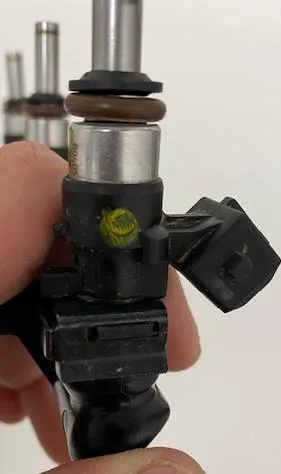
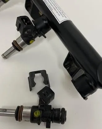
With brake cleaner, spray around all (3) injector ports and fuel rail. Wipe debris away with a rag. Turbo and Turbo R models press the metal clip down and remove the connector from the injector. Remove the fuel hose from the fuel rail. Push the connector in and spread left/right side away from the fuel rail. Remove the fuel rail, keep the O-rings with the fuel hose. Remove the (2) fuel rail screws.
- Step 4
Remove the injector clip, once the clip is removed you can pull the injector out of the fuel rail. Install the EVP injectors, use dielectric grease on the o-rings allowing for easier installation. Place the injector clip back onto the fuel rail, make sure the clip is in both grooves. Reinstall the fuel rail in reverse order.
Need technical support?
Submit a ticket with your vehicle and what you're seeing, and our support team will get back to you.
