 BUY NOW, PAY LATER. Starting at 0% APR


Parts Included in RT-125 Turbo Upgrade System
Polaris 2018-2024 Ranger XP 1000 RT-125 Turbo Upgrade System
2018-2024 Ranger XP 1000 RT-125 Turbo Upgrade System
Before you start
Note
First step to this turbocharger upgrade is sending in your ECU to be flash, expect 48 hour turn around time, or connect your CodeShooter and flash your ECU.
In the box
Parts and tools
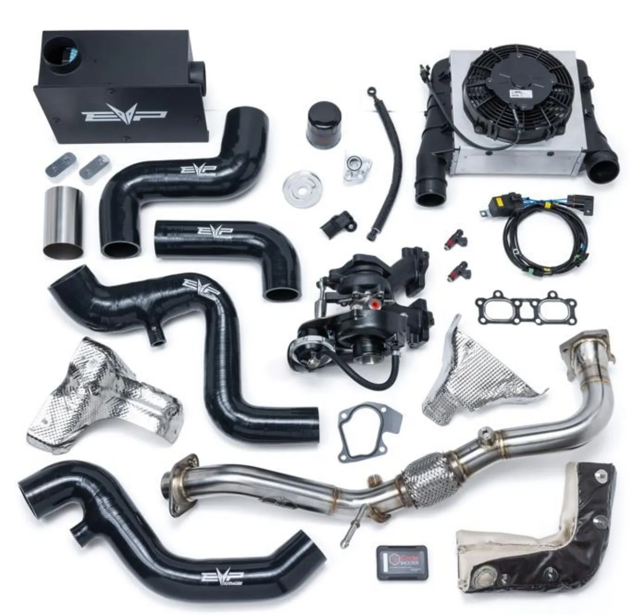
| 203FP0136 | Ranger Turbocharger Air Intake Assembly |
| 604FP0142 | Ranger Turbocharger Assembly |
| 953RU0727 | Ranger Turbocharger Installation Kit |
| 300FP0406 | Ranger Turbocharger Exhaust System for OEM Muffler |
| 804FP0335 | Ranger Turbocharger Oil Filter Adaptor Kit |
| 100FP0229 | Ranger Turbocharger Intercooler Assembly |
| 100FP0230 | Ranger Charge Tube Kit, Black |
| 708FU0016 | CodeShooter ECU Flashing Device Retail (Optional) |
| 705RP0024 | Polaris CodeShooter Cable 2017+ CS-POL-2 (Optional) |
Parts Included RT-125 Install Kit
| 804FP0231 | Polaris 2 Cylinder Stainless Steel Turbo Manifold Gasket | 1 |
| 953RU0700 | M6-1.0 x 10mm Flanged Button Head, Stainless | 6 |
| 604FP0137 | XP Turbo OEM Turbocharger Lower Heat Shield | 1 |
| 604FP0138 | XP Turbo OEM Turbocharger Upper Heat Shield | 1 |
| 953RU0602 | 8AN Push Lock Hose | 13 |
| 953RU0079 | 3/4” Black Silicone Fire Sleeve | 10 |
| 953RU0606 | 16-27mm Worm Drive Clamp | 1 |
| 953RU0158 | 24.1mm Pinch Clamp | 1 |
| 953RU0690 | M16 x 1.5 x 38mm Banjo Bolt | 1 |
| 953RU0691 | M16 Banjo Fitting to 13mm Barb | 1 |
| 953RU0692 | M16 x 20 x 1mm Copper Washer | 2 |
| 705RU0029 | Bosch 3 Bar MAP Sensor | 1 |
| 500FP0068 | Injector Adaptor, EV1 to EV6 | 2 |
| 501RP0008 | RZR 850CC Injector | 2 |
| 953RU0023 | Zip Tie | 10 |
| 953RU0177 | M8-1.25 x 25mm Socket Head Bolt SS | 6 |
| 953RU0482 | M8 Spring Lock Washer, Zinc Flake | 6 |
| Level | Tunes | Max Boost (psi) | Spark Plug Gap | Spring | Waste Gate (psi) | Engine HP |
|---|---|---|---|---|---|---|
| RT-130 | 91 | 6.5 | .020” | Brown/Black | 3.5psi | 125 |
Optional Parts (Sold Separately)
| Blow Off Valve Kit |
| Oil Change Kit |
| Turbocharger Muffler |
Procedure
Installation
- Step 1
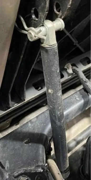
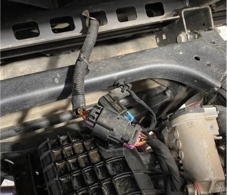
Wash the vehicle firewall, engine bay and underneath the rear seats. Remove the bed shock, label top/bottom with tape. Cut zip tie holding the box wiring harness, unplug the electrical connector. Some models may have two connectors.
- Step 2
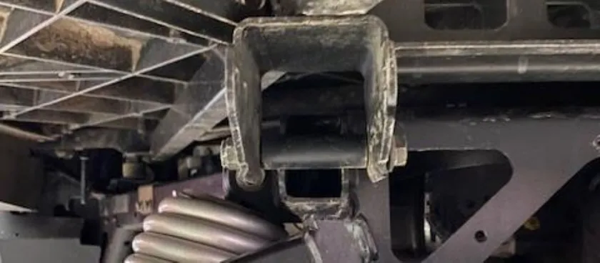
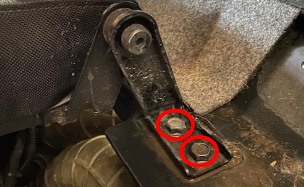
Remove two rear hinge brackets using a 15mm socket and wrench. Remove bed.
- Step 3
Remove rear seat bottoms. The driver side lifts up from the back, pull front out of hinges. Passenger seat will need to remove shock, (2) 13mm screws with bracket, and M6 Allen with 17mm nut with two grommets in between.
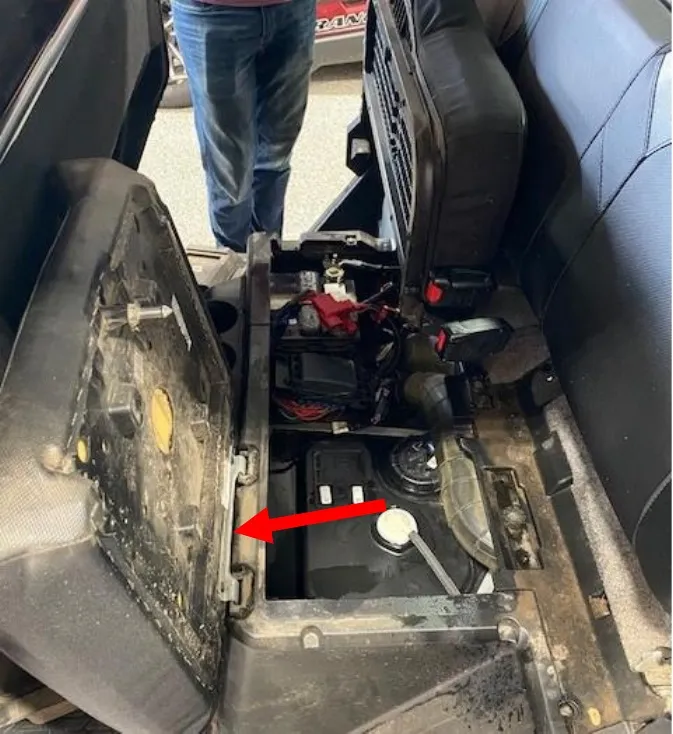
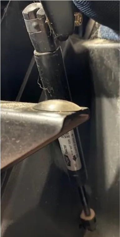
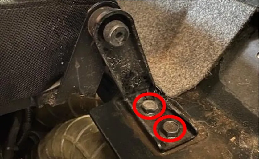
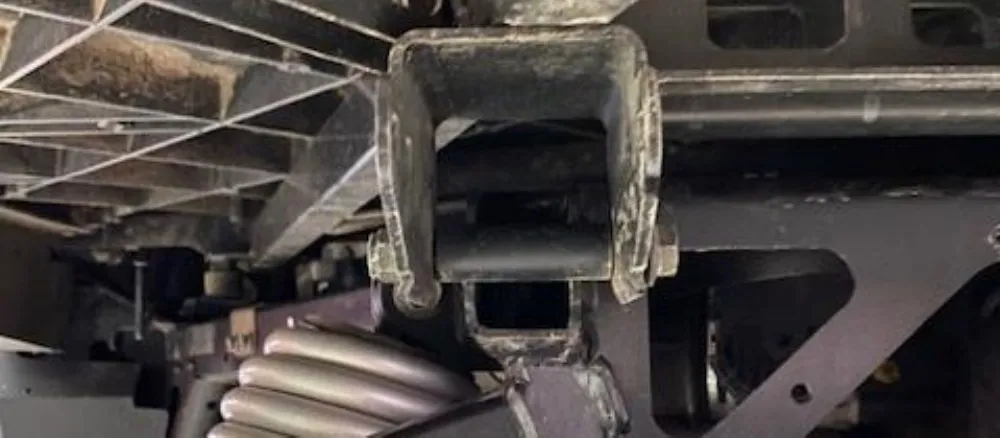
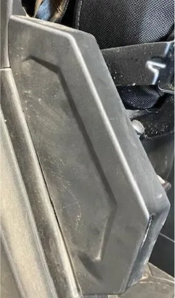
Before removing the M6 Allen and 17mm nut, remove this plastic cover. There are (2) T-40 screws on the backside.
- Step 4
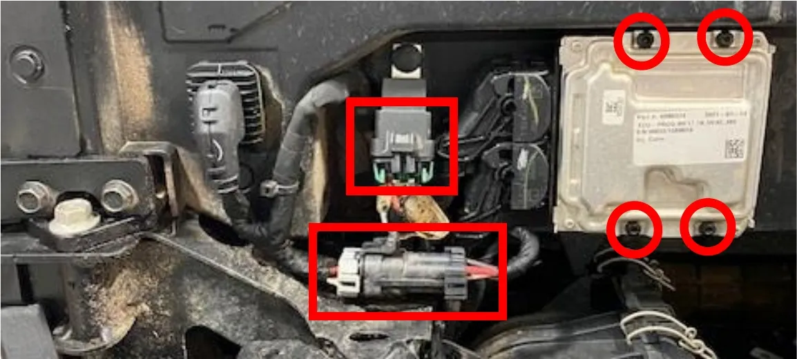
On the outside of the firewall, remove the ECU (4) T-25 screws. Reinstall into the plastic once ECU removed. Unplug Relay next to ECU, disconnect the electrical connector mounted to the frame.
Notebefore doing this, make sure your front windows are up/down because they wont work after this is completed.
- Step 5
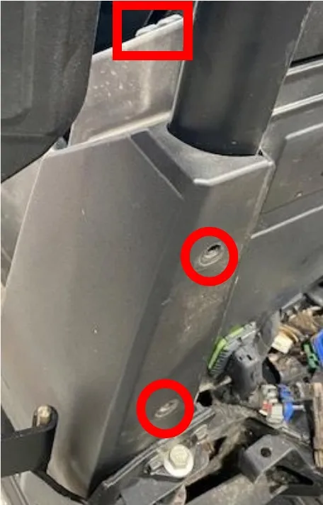
Remove the rear window, set in a safe place. Remove the two-firewall endcap hardware (don’t need to fully remove end caps) by removing (2) push parts and (2) T-40 screws located on the inside of the cab.
- Step 6
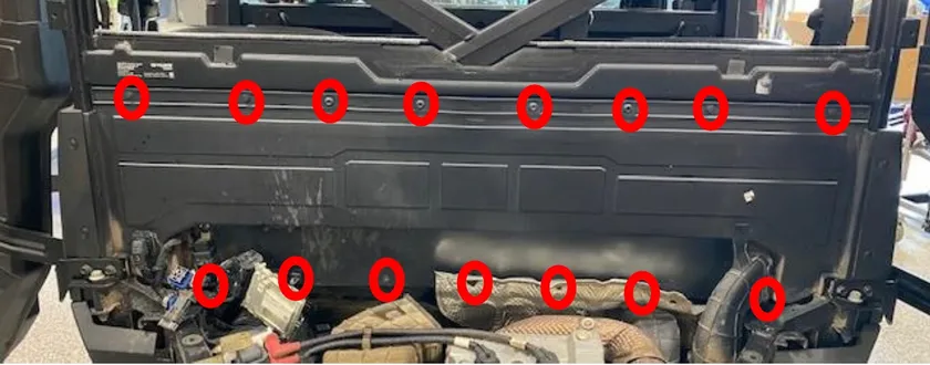
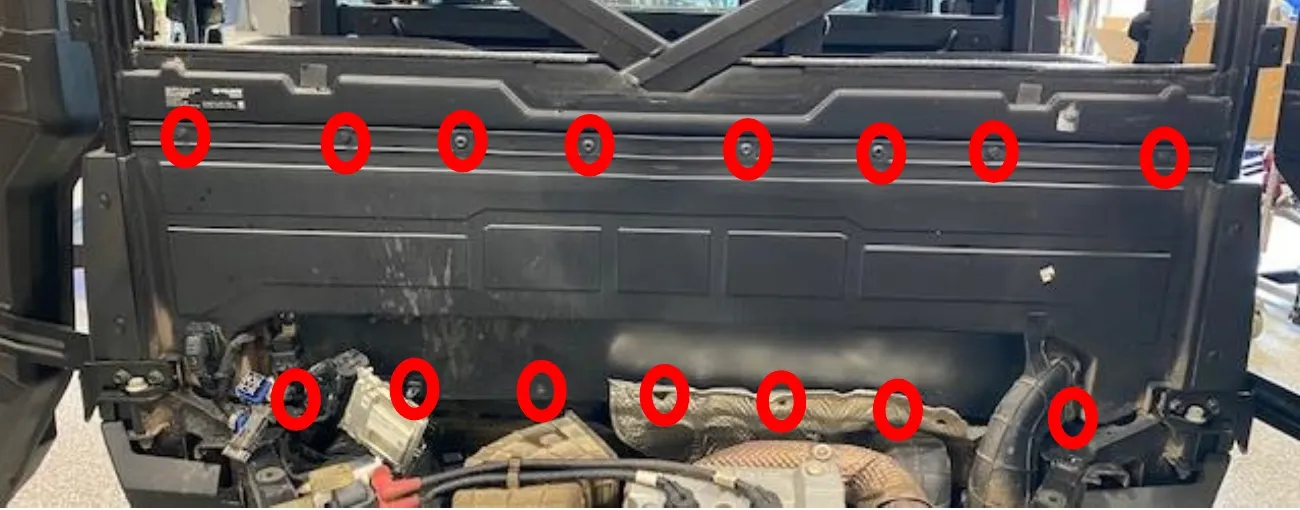
Remove the rear firewall from the outside. Remove (8) push darts, (8) T-40, and (2) 10mm screws. Some later models have a trim piece across the top, remove that as well.
- Step 7
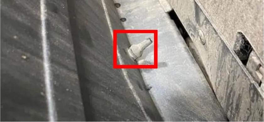
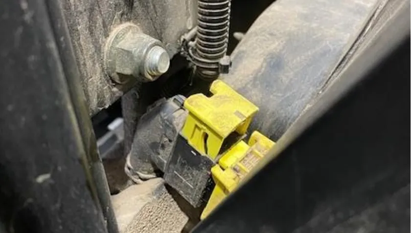
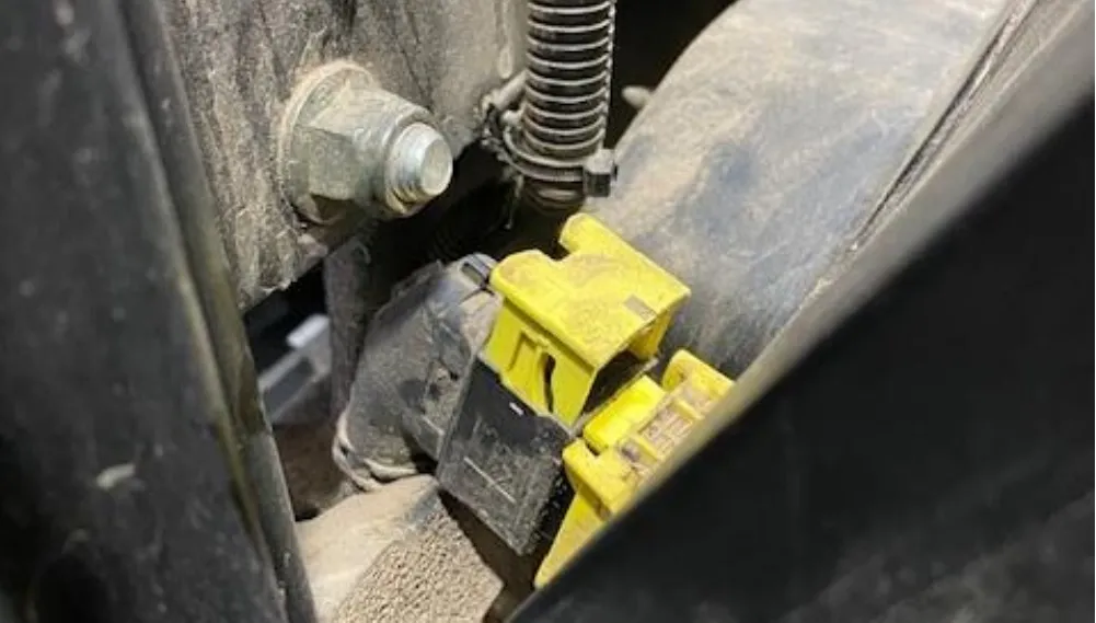
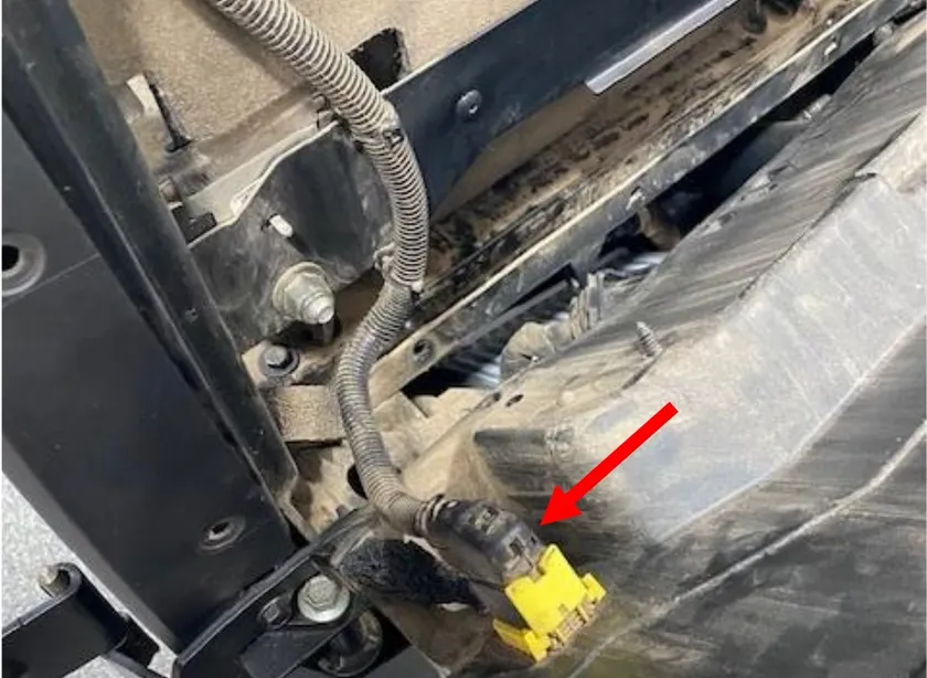
Pop the end caps around the firewall, tilt the top backwards. Push the AC compressor tube grommet out of the firewall. Some vehicles may have a T-40 Torx instead of a grommet. On the drivers side firewall (located by the ecu) pull the yellow connector upward and remove the plug from the backside. Leave the connector with green seal in the firewall.
- Step 8
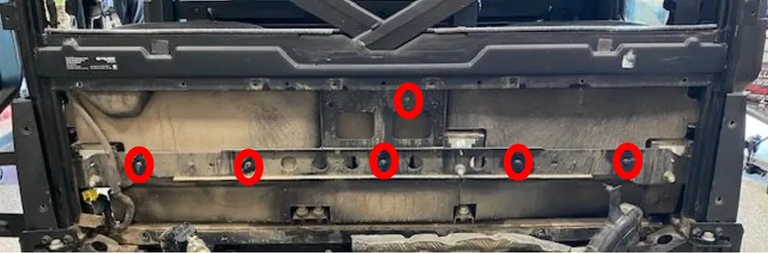
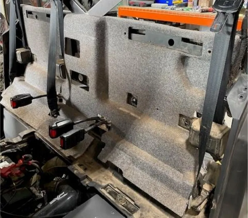
Remove (6) T-25 screws holding the backseat pads in. Remove back seats, the tops are clipped in.
- Step 9
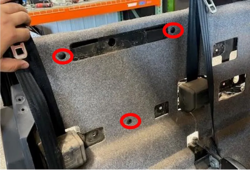
Remove (6) push darts holding in the sound dampener carpet. Remove from vehicle.
- Step 10
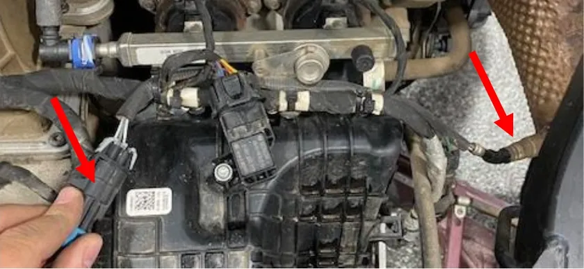
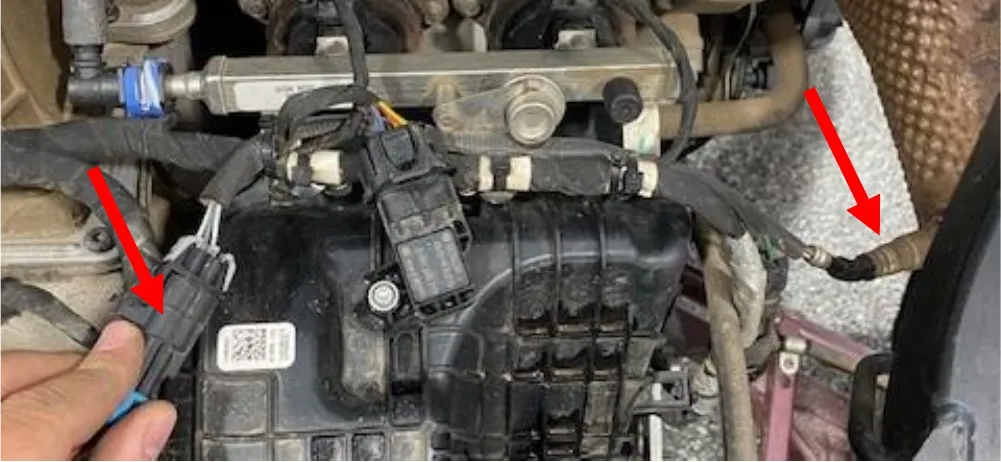
Loosen the 02 sensor with a 22mm wrench. Unplug the 02 sensor and cut zip ties holding the pigtail onto the harness.
- Step 11
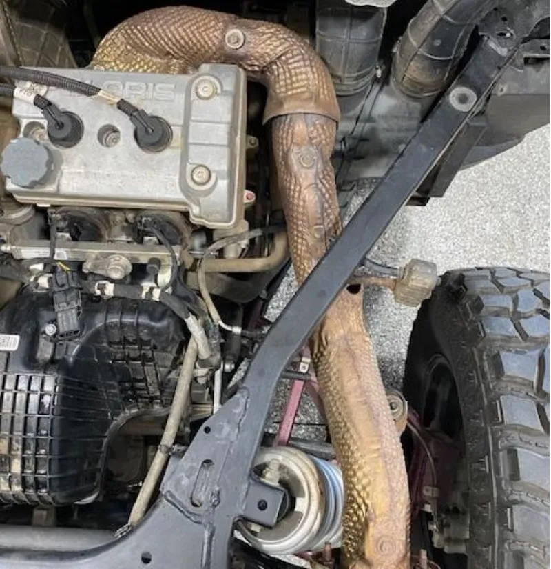
Remove OEM heat shields from header, mainly the heat shields closest to the head.
- Step 12
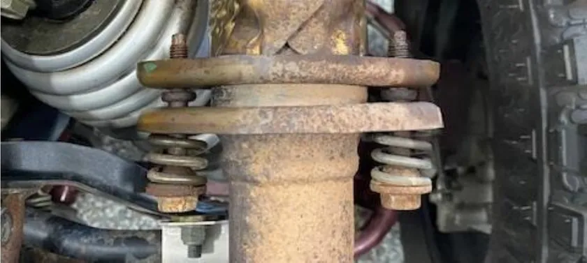
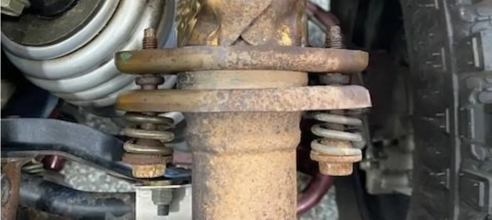
Spay penetrating oil on the downpipe/muffler flange hardware. Remove the hardware with a 15mm socket, remove the springs. If the bolts are defected, replace them. PN: 7520079.
- Step 13
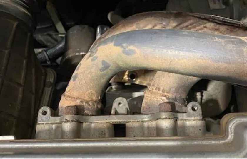
Remove (6) M6 screws holding the head pipe to the head. Ball-end Allen works best.
- Step 14
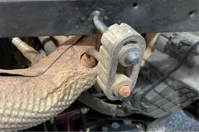
Remove the rubber isolator from either chassis or head pipe. Remove head pipe.
- Step 15
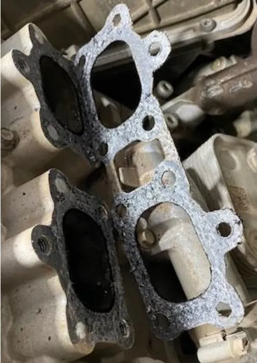
Remove the OEM exhaust gasket. Use a razor blade and cleaner. You want this cleaned up well, DON’T let debris fall into the head. Using a vacuum helps.
- Step 16
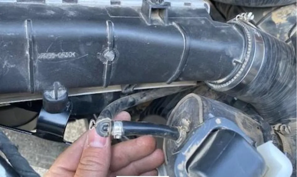
Remove the crankcase breather tube from the throttle body tube. Keep the self-tightening clamp. Remove the (2) worm drive clamps holding the throttle body tube on, remove tube.

- Step 17
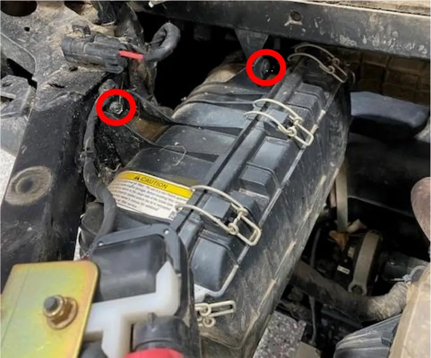
Remove (2) 10mm screws and (1) push dart holding the OEM airbox in place. Pull it into the engine bay and remove the worm drive on the fresh air intake tube.
- Step 18
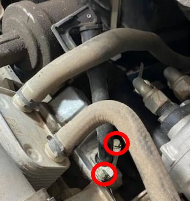
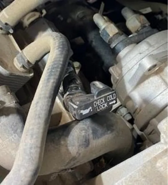
Clean around the dip stick tube bracket with compressed air and cleaner. Remove the dip stick. Remove (2) 8mm screws holding the dip stick bracket on, remove the tube and clean. Flip the dip stick tube 180 degrees and reinstall hardware and dip stick.
- Step 19
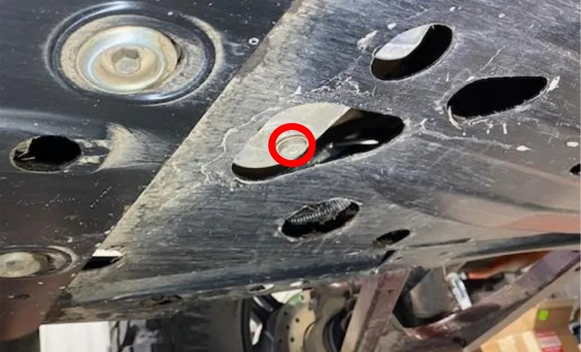
If you aren’t changing oil at this time, skip to step 20. It is recommended. Remove the drain plug with a 6mm Allen. Drain oil into a catch pan. Once finished, reinstall a new sealing washer and reinstall the drain plug.
- Step 20
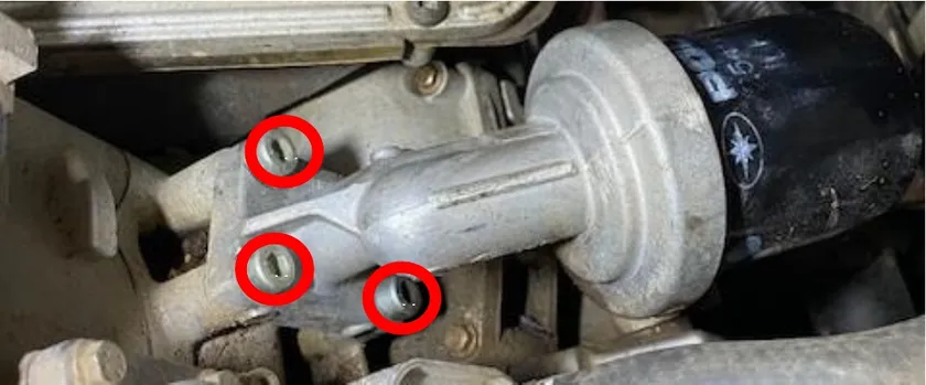
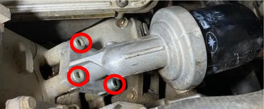
Clean around the oil filter and housing with compressed air and cleaner. Place rags underneath the housing. Remove (3) 6mm Allen screws holding the oil filter housing to the block. Remove the housing with O-rings, holding the filter downward. You shouldn’t spill oil this way.
- Step 21
With the housing on the work bench, spin off the oil filter and disregard. With a 12mm Allen, remove the oil filter stud from the housing.
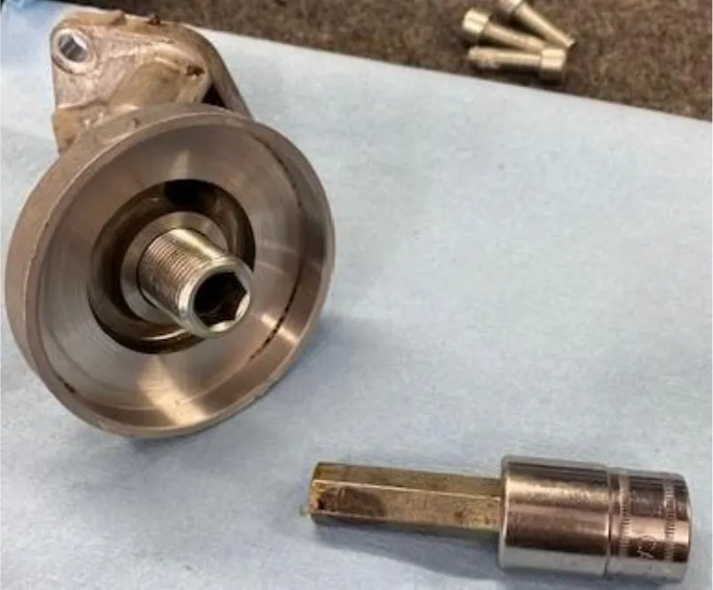
- Step 22
Below is a photo of the oil filter adaptor kit.
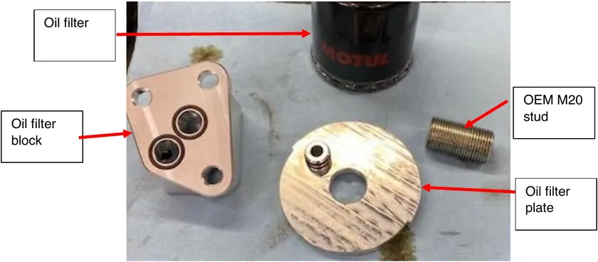
- Step 23
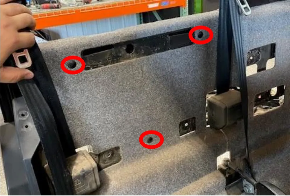
Install the OEM M20 stud into the oil filter block, tight. The block will have (2) O-rings on the backside mating to the engine block, and (1) larger O-ring on the front around the M20 stud.

- Step 24
Clean the oil filter housing location on the engine block with cleaner. Apply oil to the O-rings and install the oil filter block to the engine. Make sure the O-rings are seated correctly. Reuse OEM hardware.
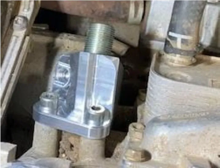
- Step 25
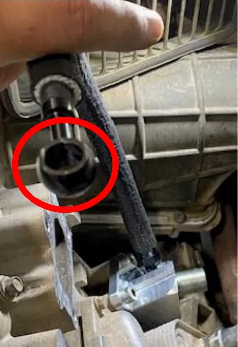
Install the 4an flare to 1/8” NPT fitting with thread tape on the NPT side, into the billet block until tight. Install the oil feed line with fire sleeve onto the 4an flare fitting. See orientation of the banjo fitting before tightening all the way.
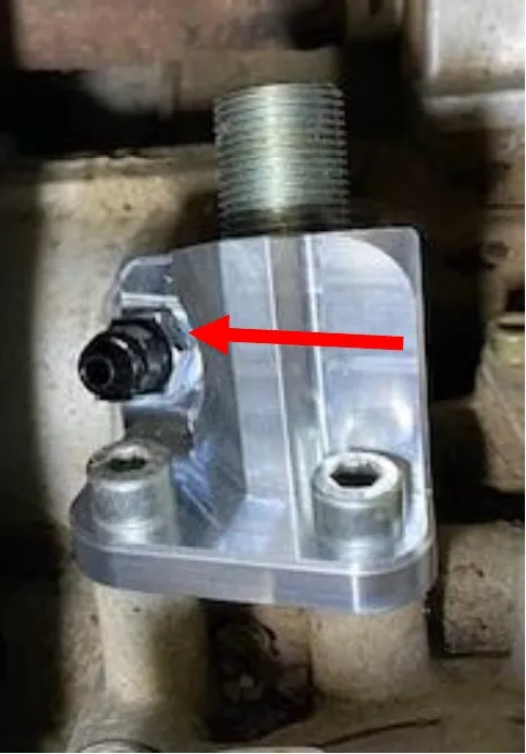
- Step 26
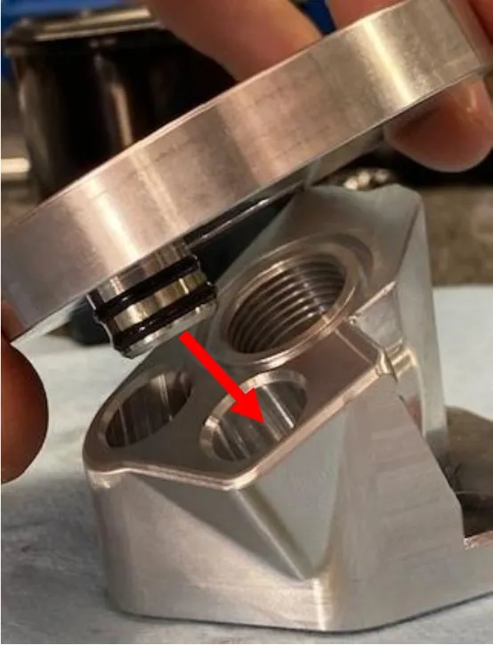
Install the oil filter plate onto the billet block. Wet O-rings with oil, line up the port with O-rings on the plate with the right port on the block, where the oil feed fitting is located.
- Step 27
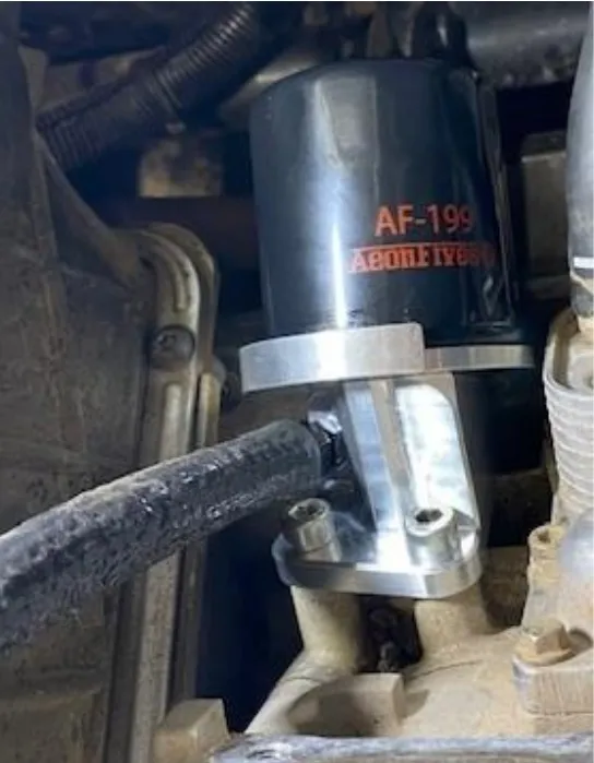
If you changed oil, fill the oil filter up 3/4 full. Wet the O-ring and install it onto the M20 stud. Tighten down hand tight.
- Step 28
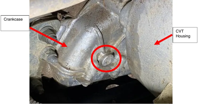
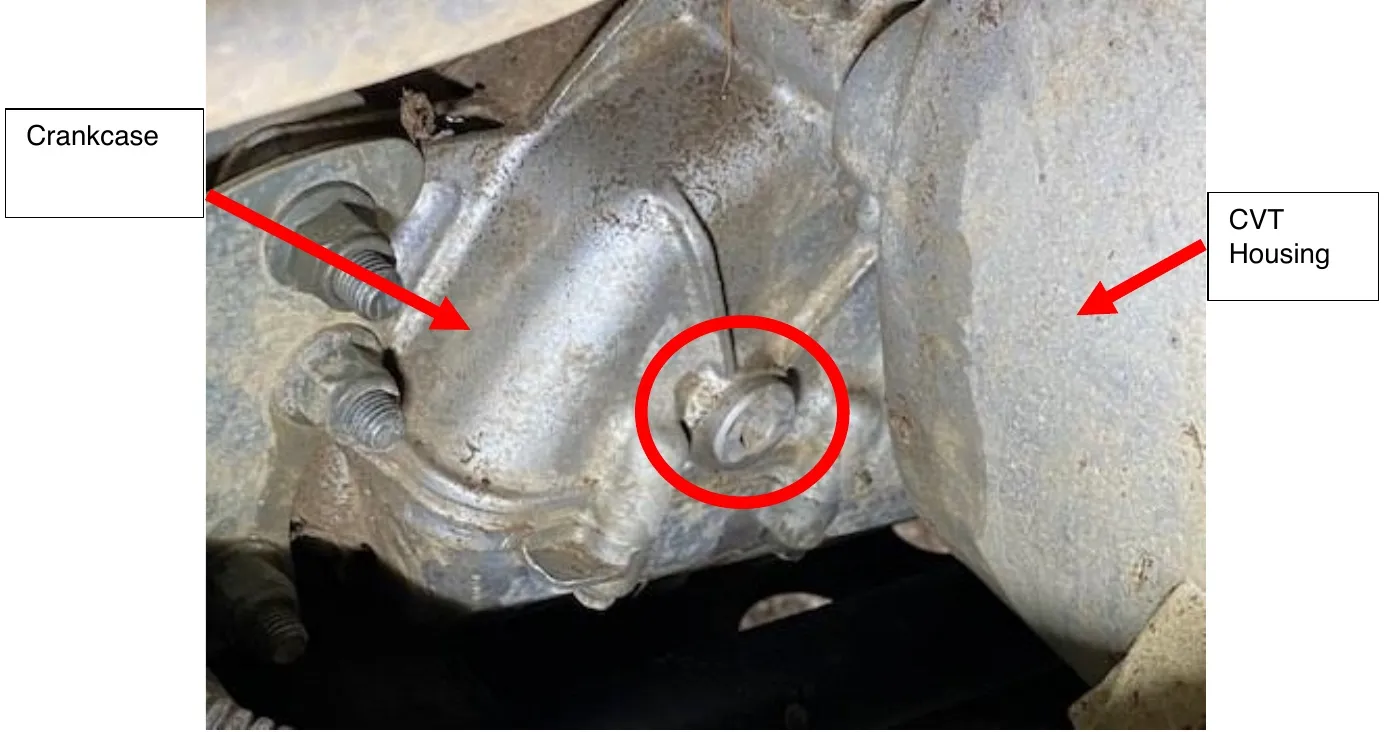
If you changed oil, add the rest of 2.5 quarts to the engine. In front of the CVT housing, you will find a 8mm Allen screw. It is easiest to access this from under the rear seats. Remove the 8mm screw and O-ring.
- Step 29
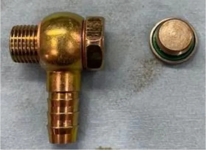
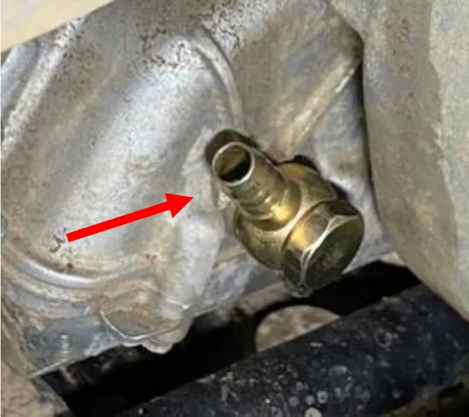
Replace the screw with the M16 Banjo bolt with fitting and crush washers. Place the barb fitting in the slot in the casting. Use a 22mm socket.
- Step 30
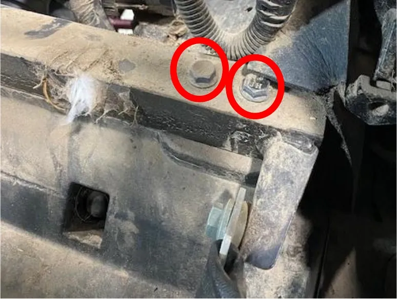
On the rear seat belt bar, remove (4) 13mm screws. Pull bar away from plastic.
- Step 31
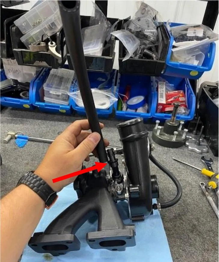
With the turbocharger upside down on the work bench, remove the RED cap from the drain. Apply dielectric grease to the barb fitting and install the push lock hose. You may need to apply some force.
- Step 32
Install the supplied 24.1mm pinch clamp on the push lock fitting. Install the fire sleeve over the push lock hose.
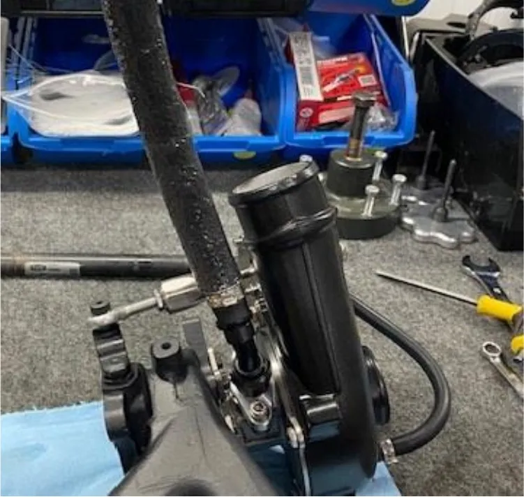
- Step 33
On the factory heat shield, cut a 2.0” line, bend both tabs back into the cab part. This will allow more room for the wastegate.

- Step 34
Install the turbocharger onto the head, use supplied gasket and hardware. Guide the oil drain hose towards the fitting but you don’t need to install it yet. Push up on the rear firewall and heat shields so gain access while installing the turbocharger. Torque hardware down to 17 ft-lb. Check wastegate clearance on heat shielding.
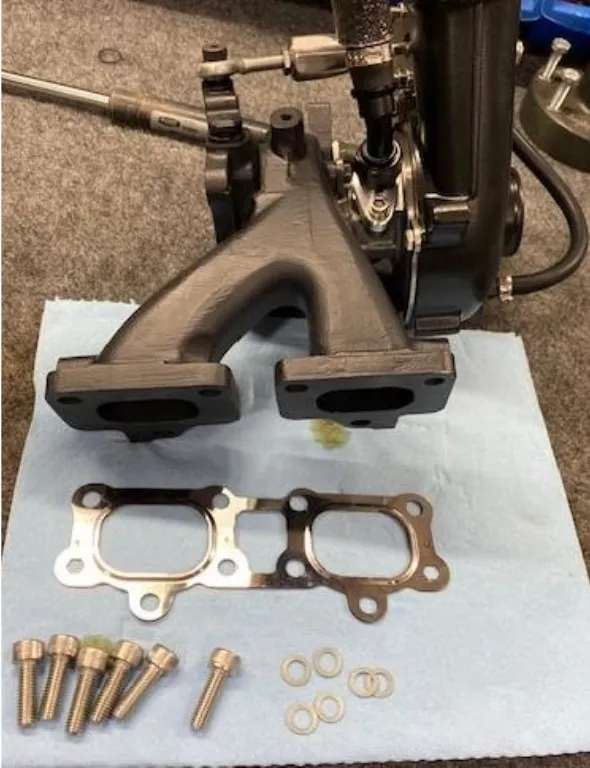

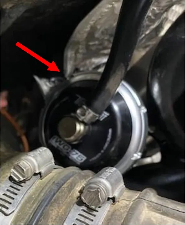
- Step 35
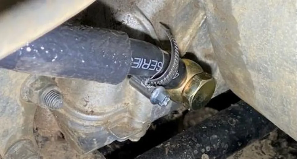
Once the turbocharger is installed, fasten down the oil drain tube to the fitting installed on the crank case. Make sure this 16-32 clamp is tight!
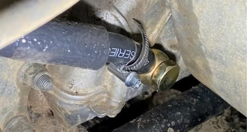
- Step 36
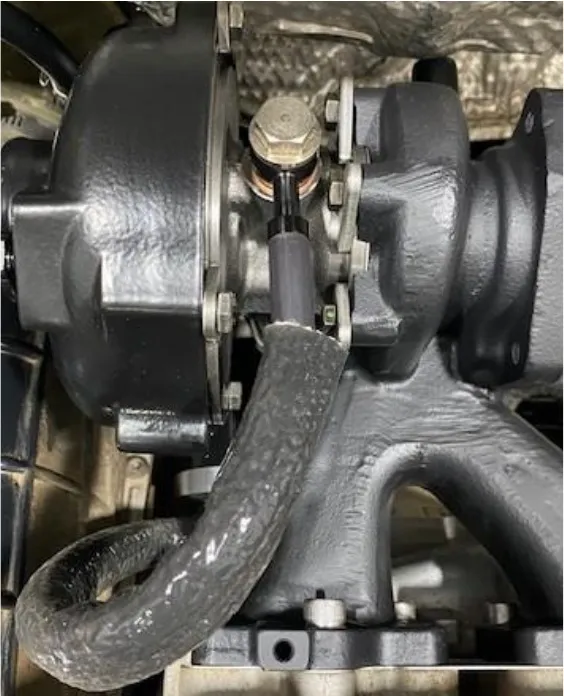
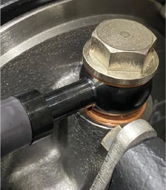
Remove the RED cap on the turbocharger oil feed port, install the M12 banjo bolt with sealing washers on both sides. Tighten down with a 14mm socket as shown below.
- Step 37
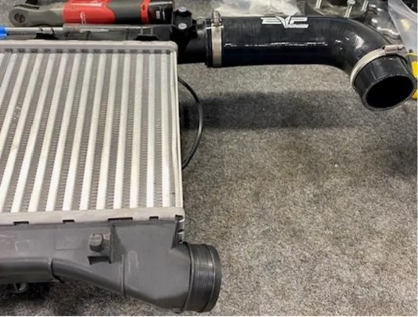
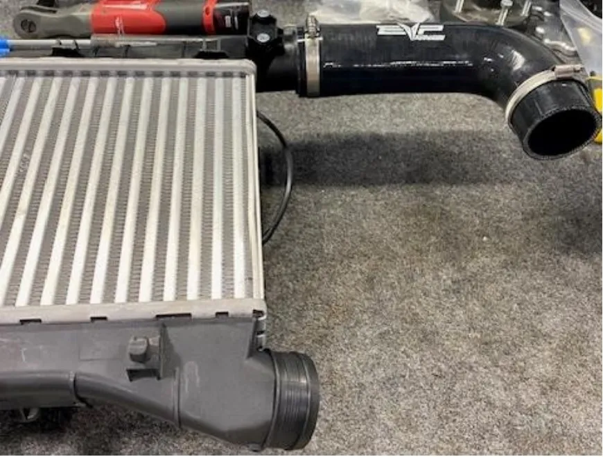
With the intercooler on the bench, install the smaller “J” tube onto the longer port. Install (2) 50/70mm worm drive clamps onto the hose but don’t tighten down.
- Step 38
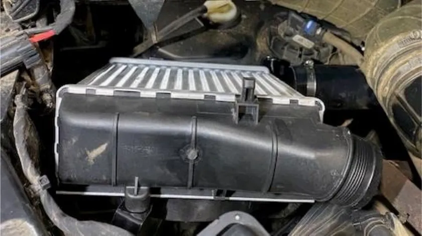
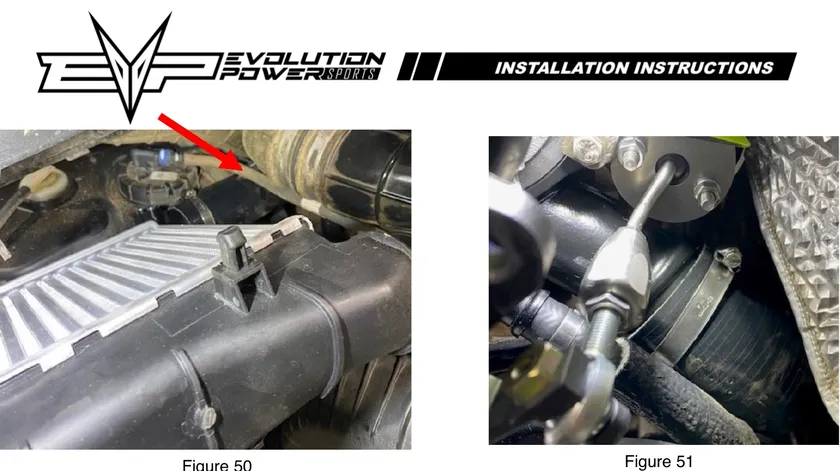
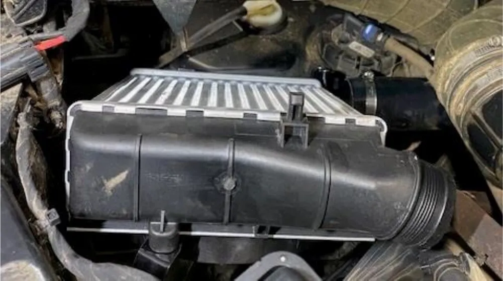
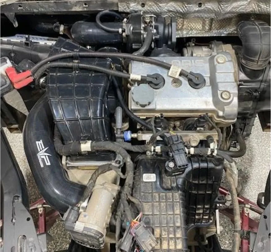
Install the intercooler into the vehicle, where the OEM airbox was located. The “J” tube goes in first , underneath the fuel line, back up to the turbocharger.
- Step 39
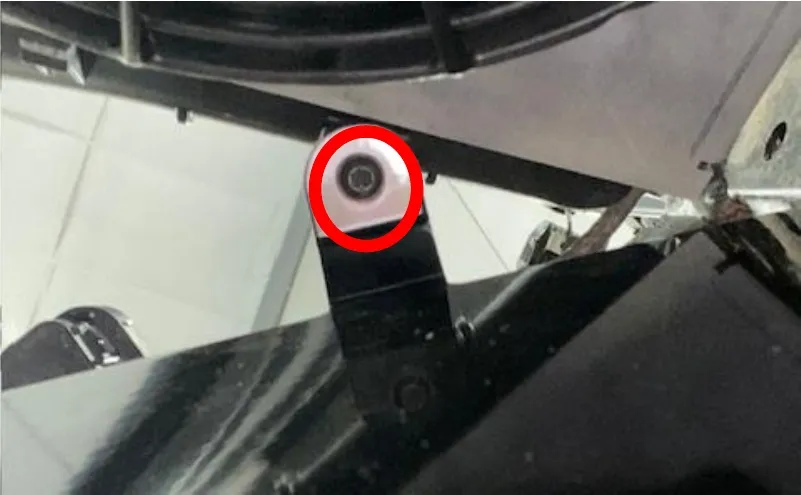
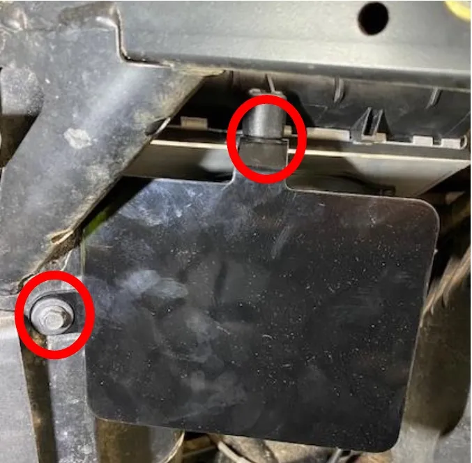
install the black support bracket reusing (1) OEM airbox screw. Install the supplied torx screw for plastic, using a T-25 socket. It is helpful to use a long extension and go up underneath. DO NOT OVER TIGHTEN.
- Step 40
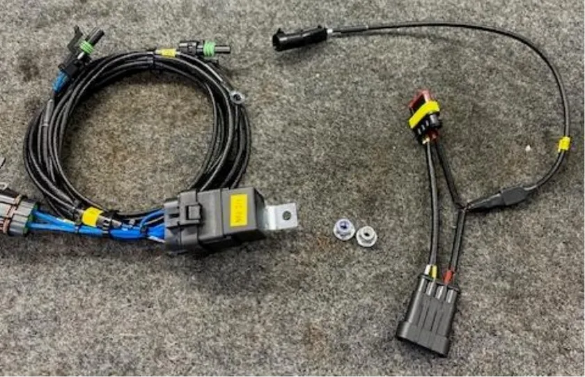
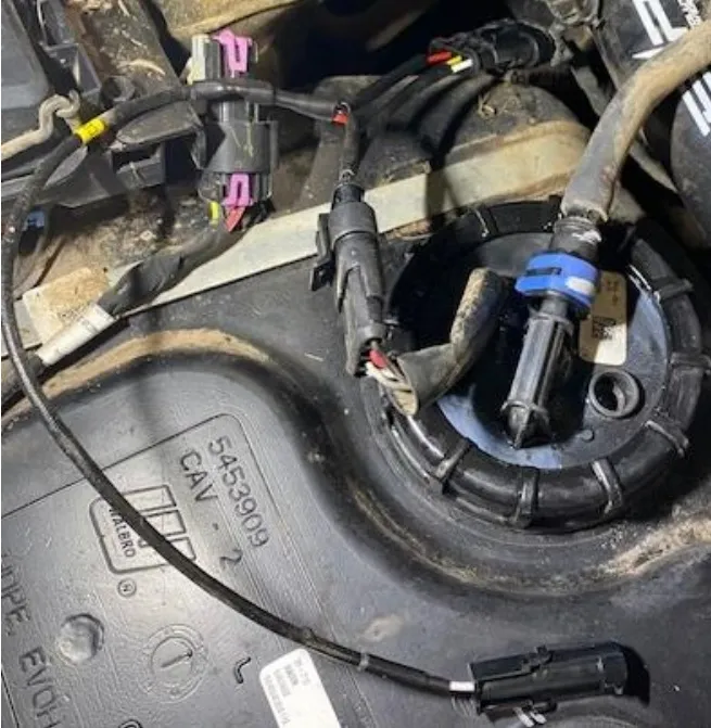
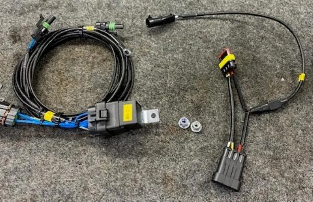
Tighten the “J” tube worm drives and make sure the intercooler support bracket is tight. Install the (2) supplied intercooler harnesses, one off the fuel pump harness and one to the battery.
- Step 41
Install the fuel pump harness into the fuel pump and the OEM harness. Leave the single connector unplugged for now.
- Step 42
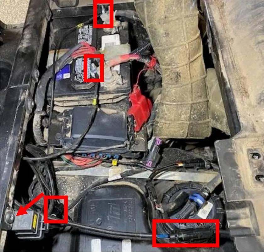
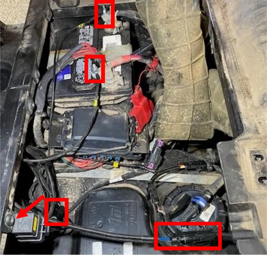
Remove (1) T-40 screw located underneath the seat, mount the relay and reinstall. Install the positive and negative to the battery, use supplied nuts to use open studs on the battery terminals. Connect the intercooler fan connector, and last connect the fuel pump single pigtail to relay single pigtail. Zip tie access wire and coil up.
- Step 43
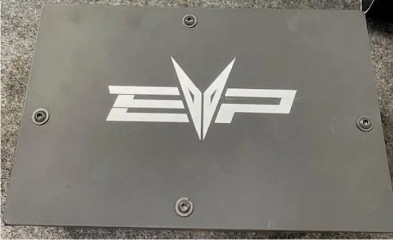
Remove the (8) M6 screws holding the lid onto the airbox.
- Step 44
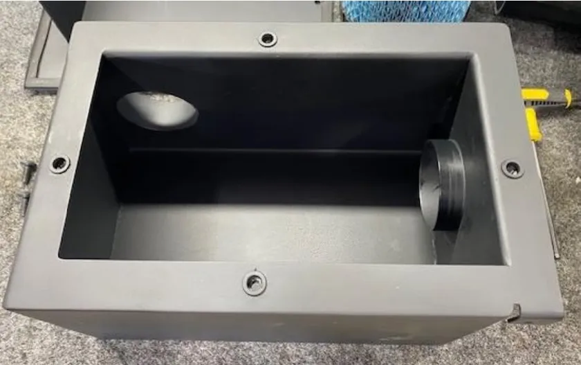
Remove the lid, remove the air filter.
- Step 45
Remove (3) T-40 screws underneath the rear driver side seats. You will only be reusing (2) screws.

- Step 46
Install the airbox, reusing (2) OEM screws.
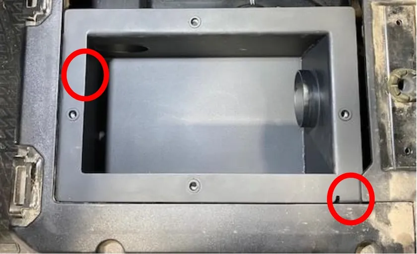
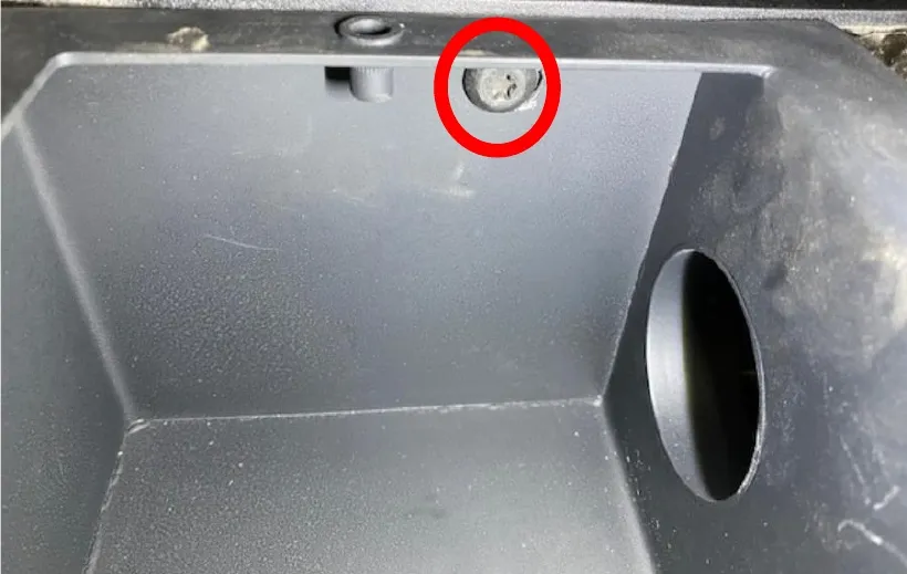
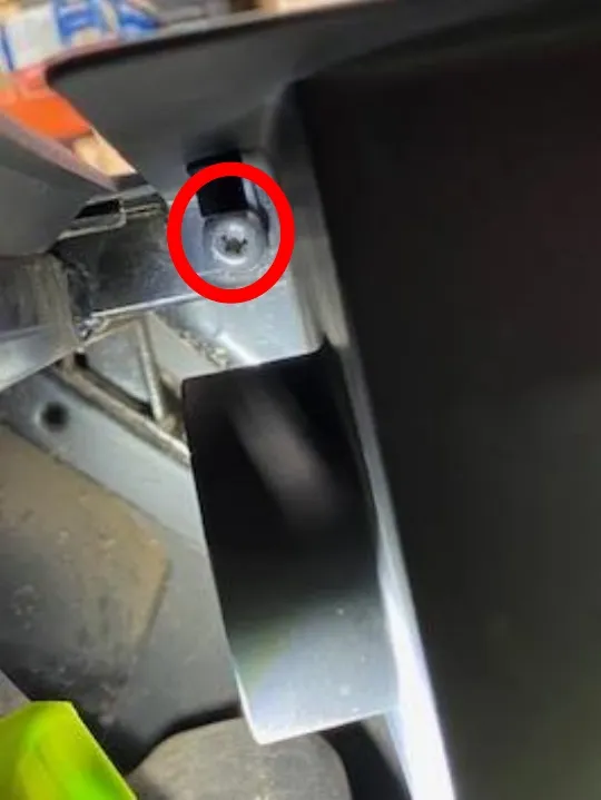
- Step 47
Install the air filter, install the lid and (8) M6 screws.
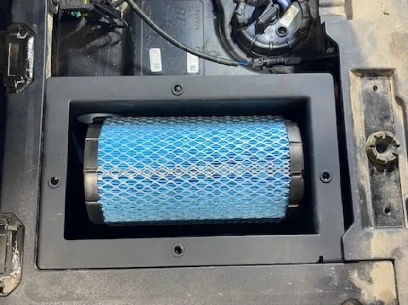
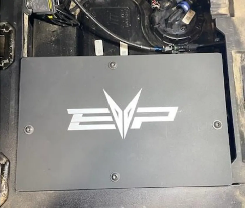
- Step 48
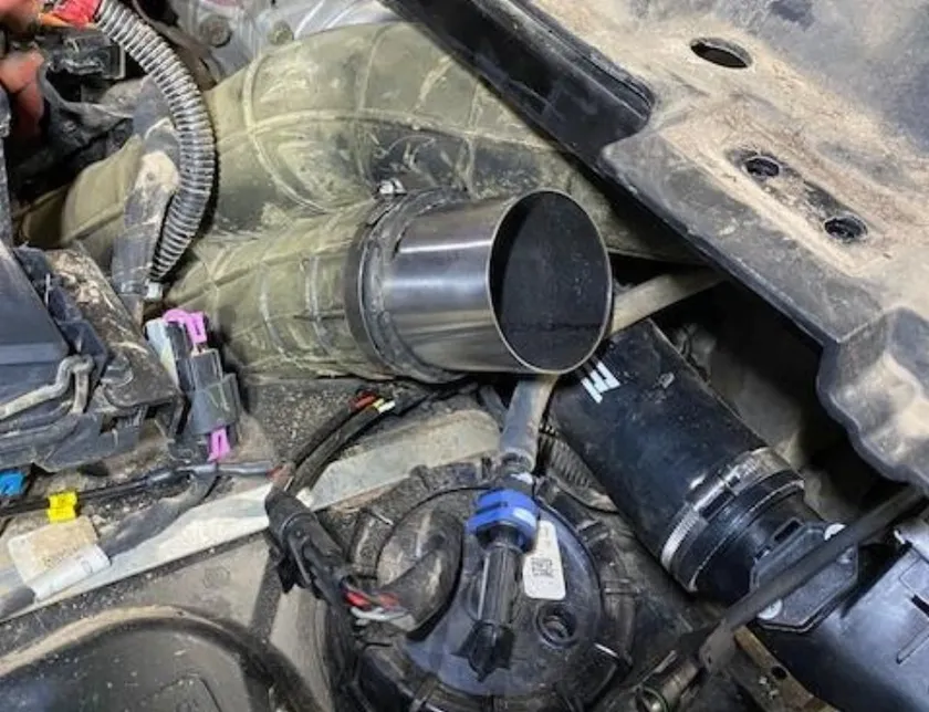
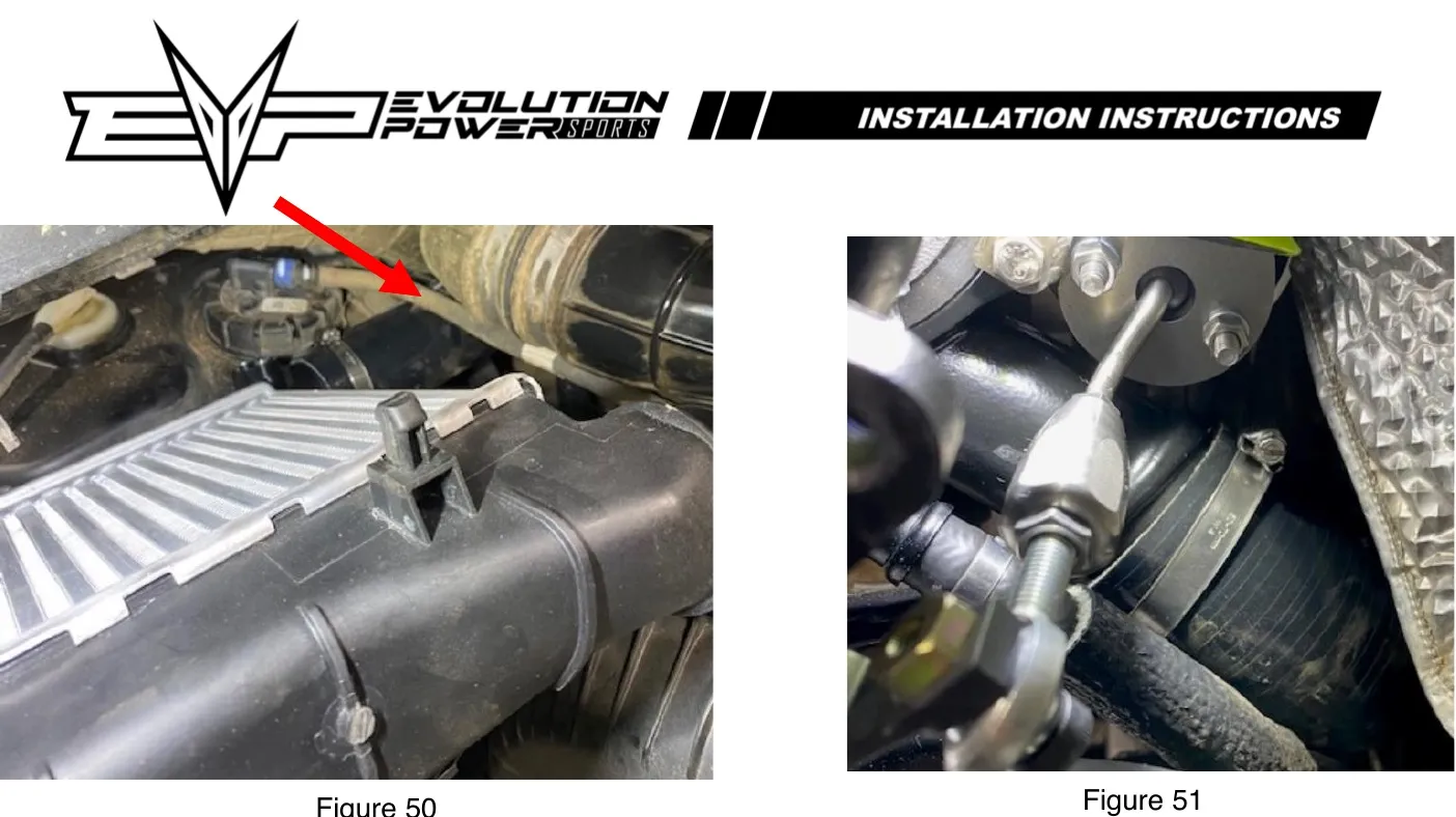
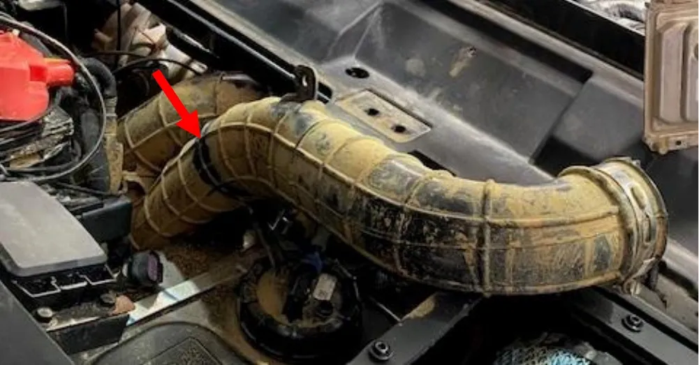
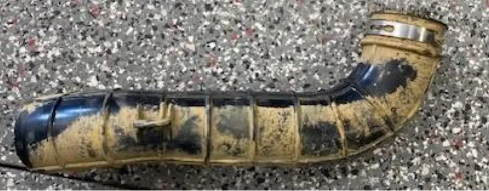
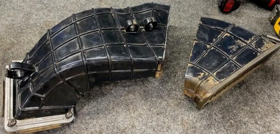
Remove the (1) push dart holding the fresh airduct in place. With a sharp blade, cut down (10) ribs from the very front. Leave the 10th rib on the piece in the vehicle, this is used for the clamp later on.
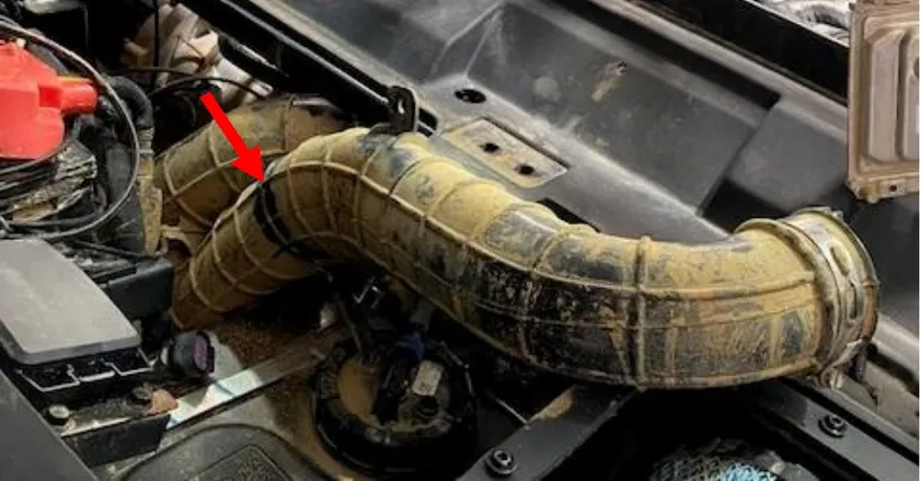
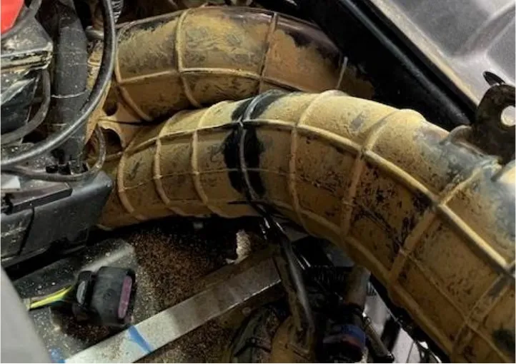

- Step 49
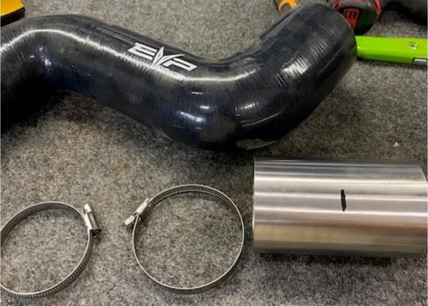
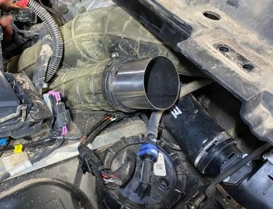
Make a mark halfway on the supplied coupler, install it halfway into the air intake duct you just trimmed. Tighten 60/80worm drive.
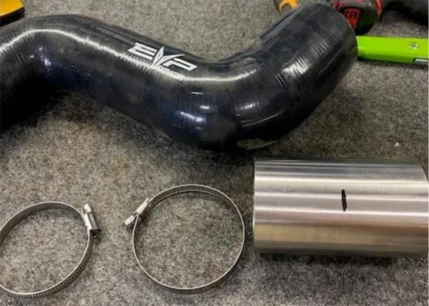
- Step 50
Install the fresh air intake from the coupler to the airbox. Fasten down with supplied 60/80 worm drives.

- Step 51
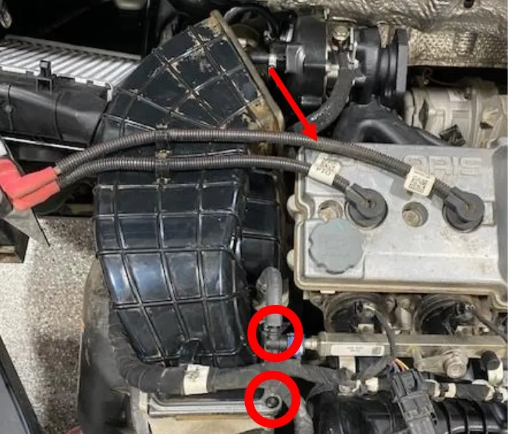
Remove both coils from the valve cover, remove (2) T-30 screws on the cvt duct.
- Step 52
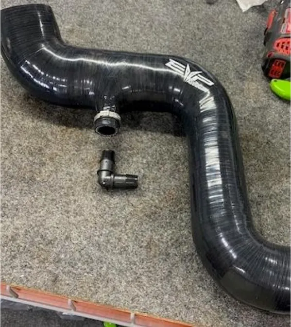
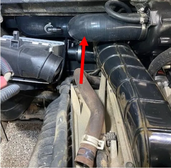
Install 5/8” 90-degree barb in intake tube from airbox to turbocharger. Use supplied 30.1mm pinch clamp. Install the tube using (2) 50/70mm worm drive clamps.
- Step 53
Cut back 2.50” off the OEM crank case hose, keep the self-tightening clamp, install onto the 90-degree barb.
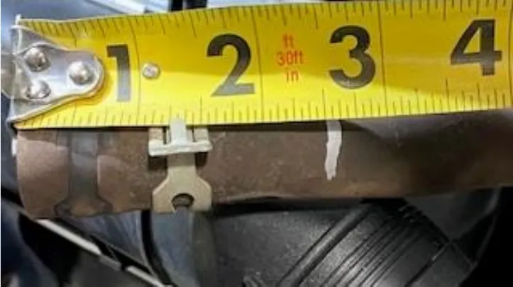
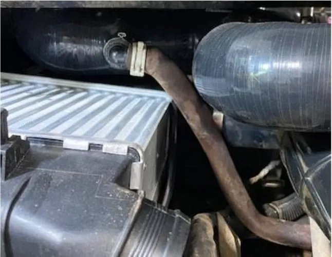
- Step 54
Install the charge tube from intercooler to throttle body, using (2) 50/70 worm drives.
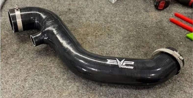
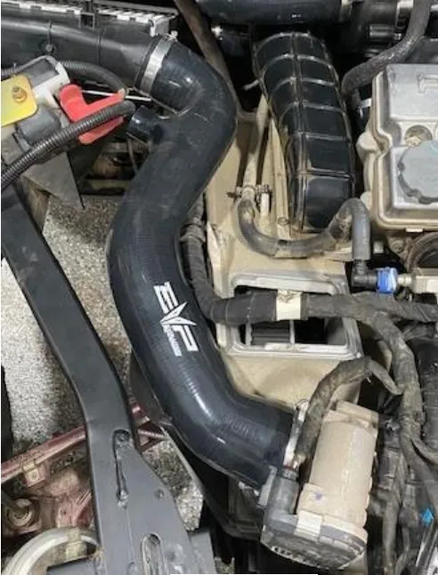
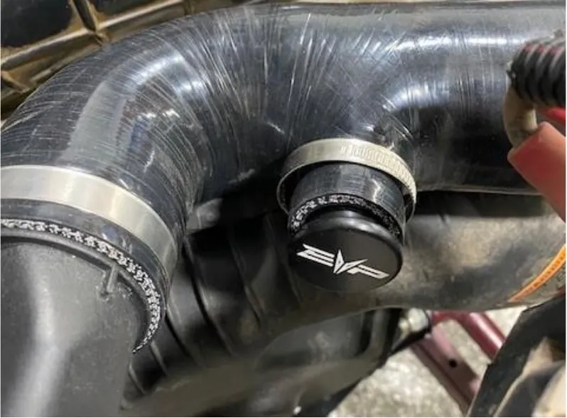
- Step 55
If you are NOT running a blow off valve, plug the 1.0” port with bov plug and 25-40mm worm drive.
- Step 56
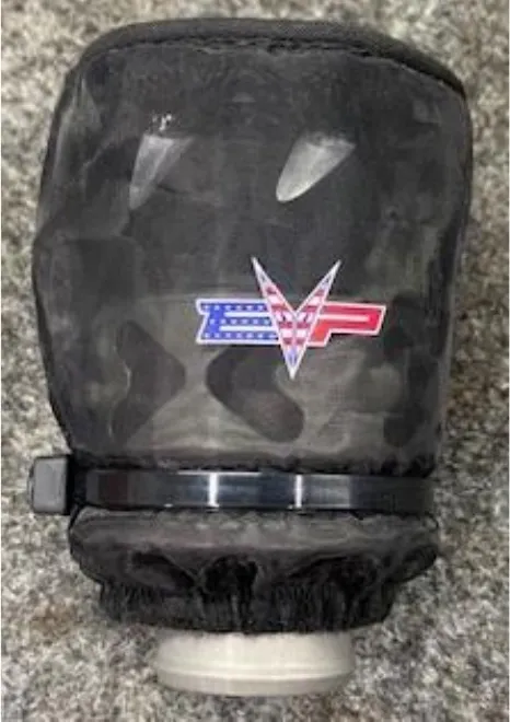
If you ARE running a blow off valve, install the pre filter around the BOV, secure with a zip tie. Install into the charge tube with 25/40mm worm drive clamp.
- Step 57
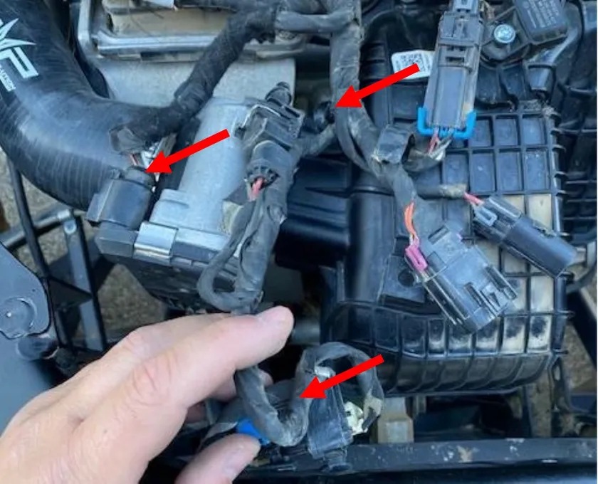
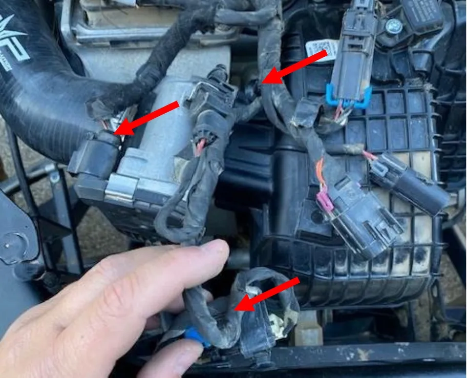
Cut (2) zip ties holding the rear harness for throttle body and bed box. Unplug throttle body, rear connector. Lay the harness over the valve cover area.
- Step 58
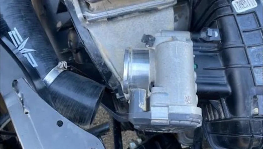
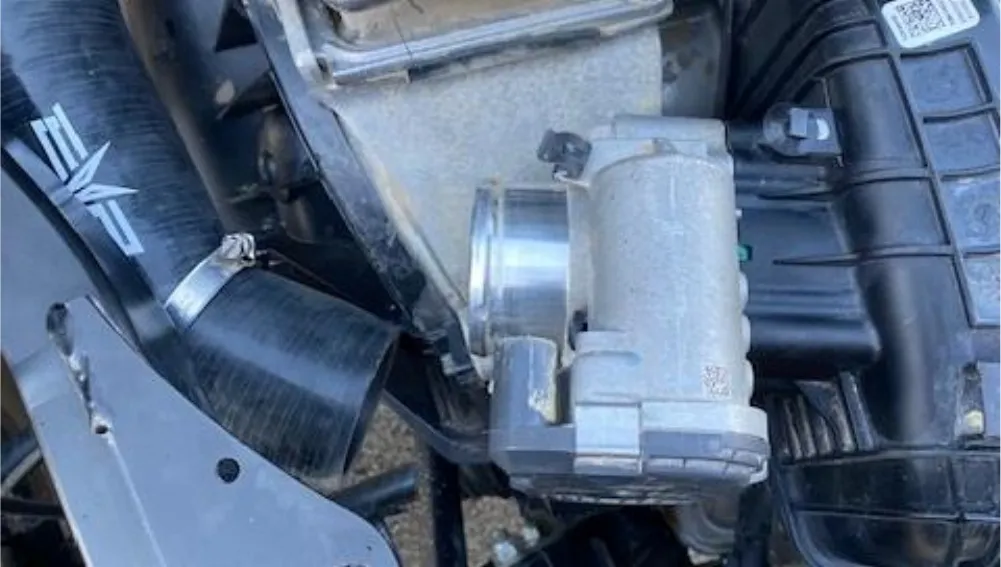
Remove charge tube from throttle body, push tube below the frame.
- Step 59
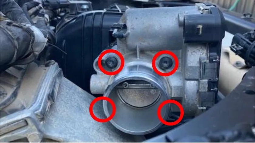
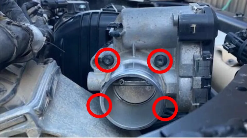
Remove (4) T-30 screws mounting the throttle body to the plenum.
- Step 60
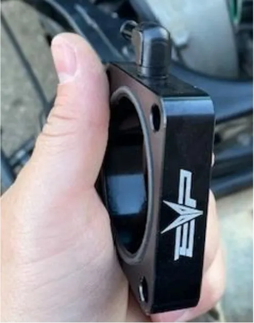
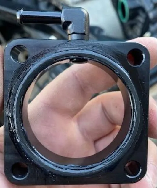
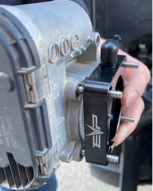
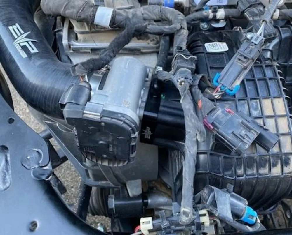
Locate the throttle body spacer and O-ring. Make sure the barb fitting is located on top, facing away from the EVP logo. Apply dielectric grease to the O-ring.
- Step 61
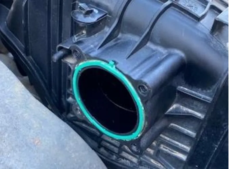
Check the plenum O-ring for cracks or tears, replace it if needed. Apply dielectric grease to this O-ring as well.
- Step 62
Install the throttle body and spacer together with supplied (4) screws BEFORE MOUNTING. Fasten down to the plenum, don’t over-tighten.
- Step 63
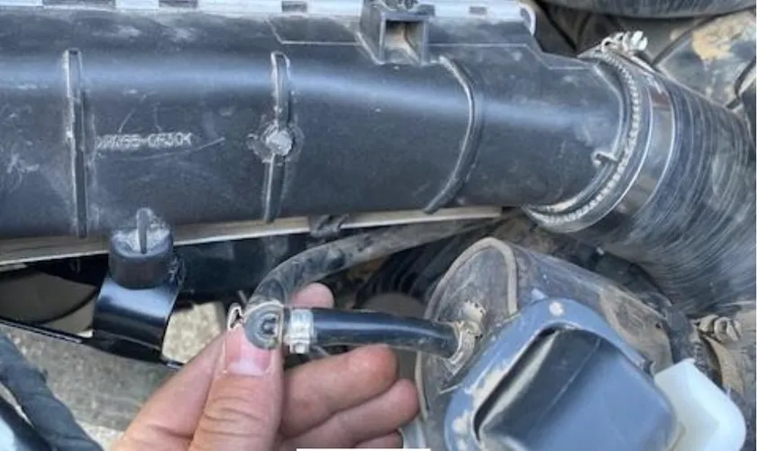
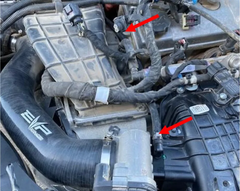
Route the vacuum line from the BOV to the barb fitting located on the throttle body spacer. Route the line under the intercooler, between the valve cover and CVT duct. Use supplied 13.3mm pinch clamp. Reinstall charge tube and clamp.

- Step 64
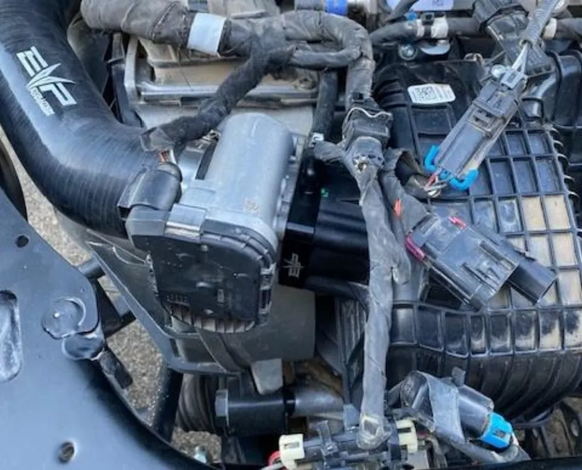
Reinstall all connectors and use supplied zip ties to remount the harness.
- Step 65
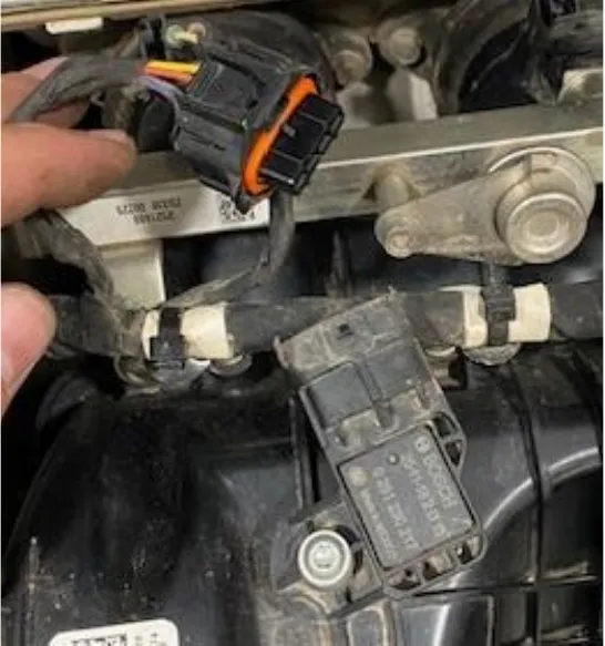
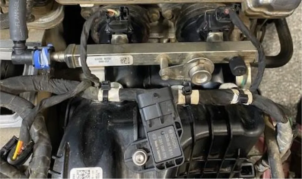
Unplug the MAP sensor from the harness, replace with MAP sensor with supplied 3 BAR and reuse OEM Torx screw to secure. Use dielectric grease on O-ring.
- Step 66
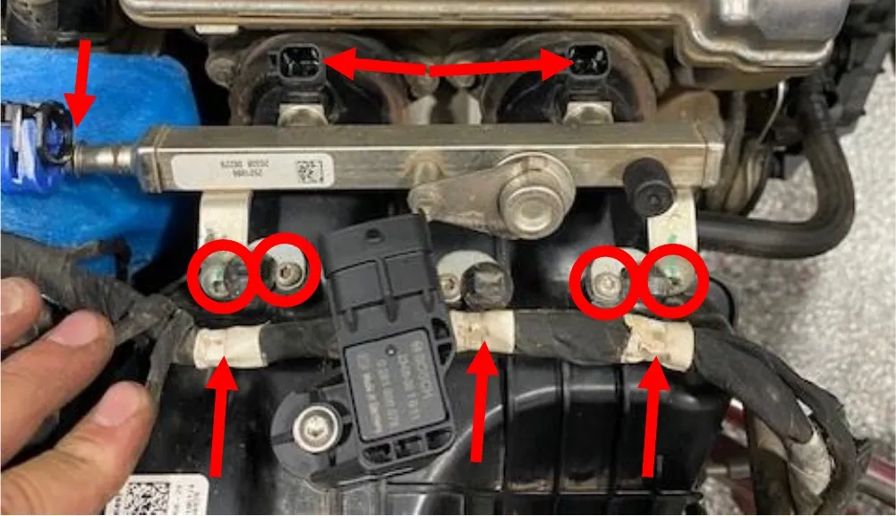
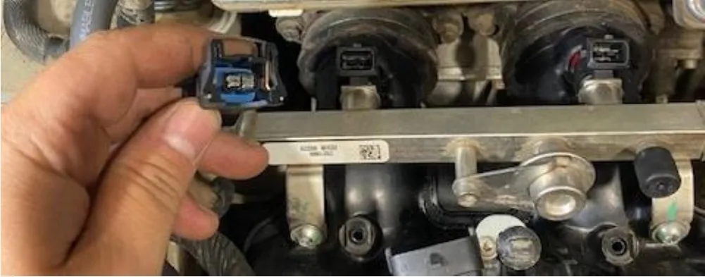
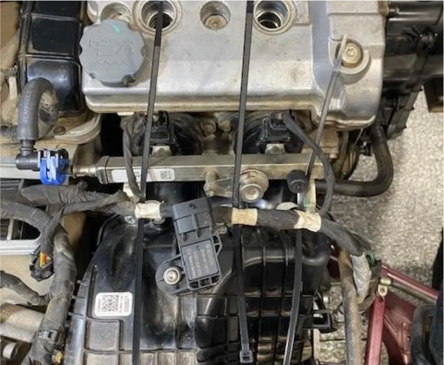
Spray around injectors with cleaner before removing. Remove the blue safety clip on the fuel rail, pack rags underneath it as it will leak fuel. Unplug both injectors from the harness, cut (3) zip ties on OEM harness located on the white tape. Remove (2) zip tie holders with T-20 socket. Remove (2) fuel rail screws using a T-30.

- Step 67
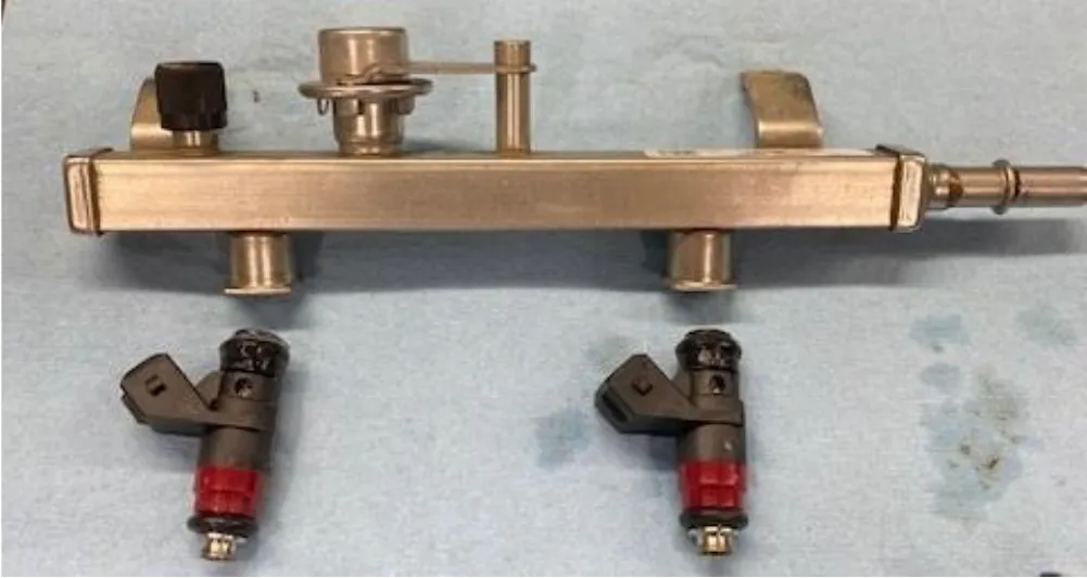
Remove the fuel rail and injectors, install new injectors and use dielectric on all O-rings.
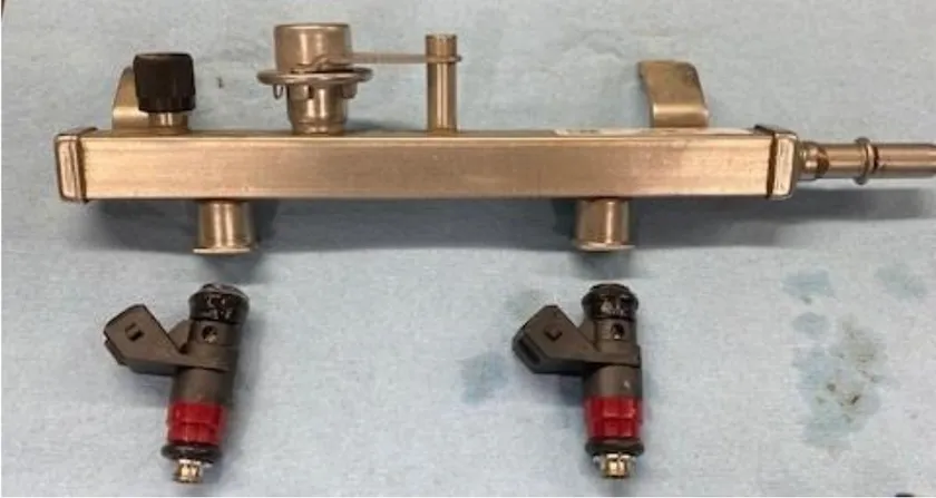
- Step 68
Reinstall the fuel rail, install supplied injector adaptors onto the injectors. Use dielectric grease. Make sure they seat/clip in all the way.
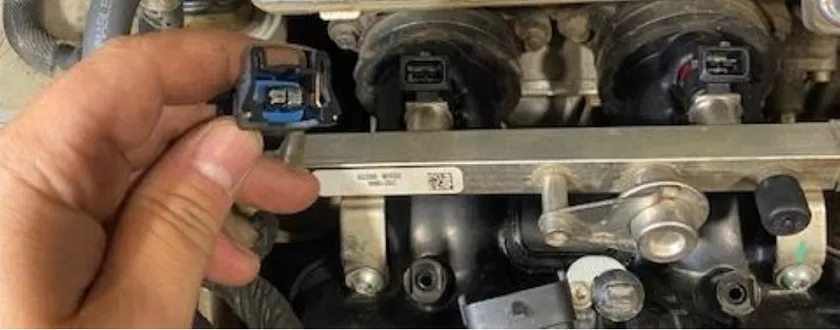
- Step 69
Reinstall injector connectors, fuel hose with safety clip, MAP sensor connector, zip tie holders and zip ties.
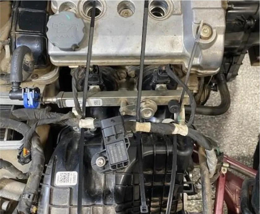
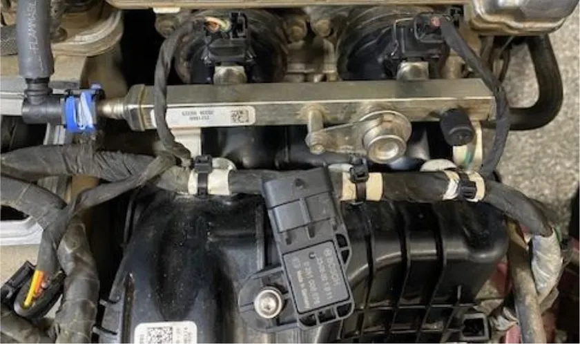
- Step 70
It is recommended to replace your spark plugs, with the coils already removed use a 5/8” socket to remove the OEM NGK-R-MR7F. Replace them with OEM or EVP Brisk plugs, gap to .020”. Reinstall.
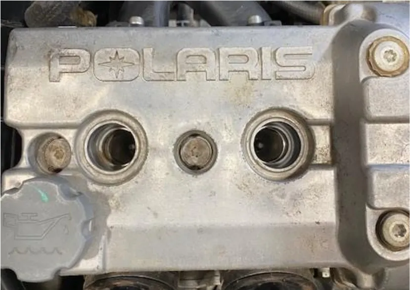
- Step 71
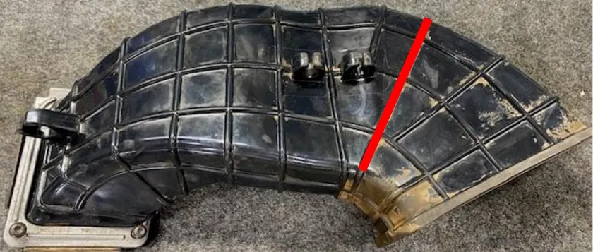
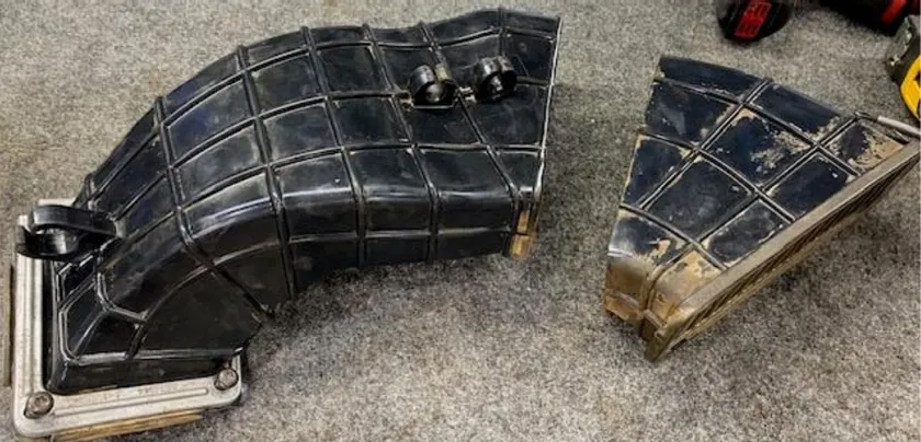
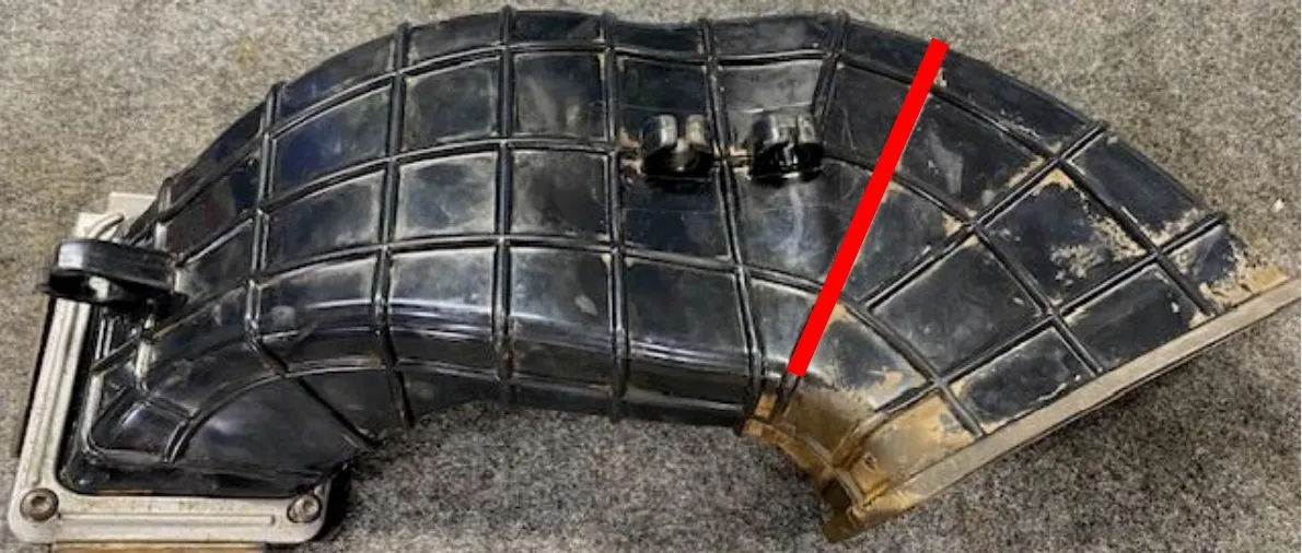
Cut the OEM CVT duct back (3) ribs, leave the third rib on the hose. Use a sharp razor blade to cut straight.
- Step 72
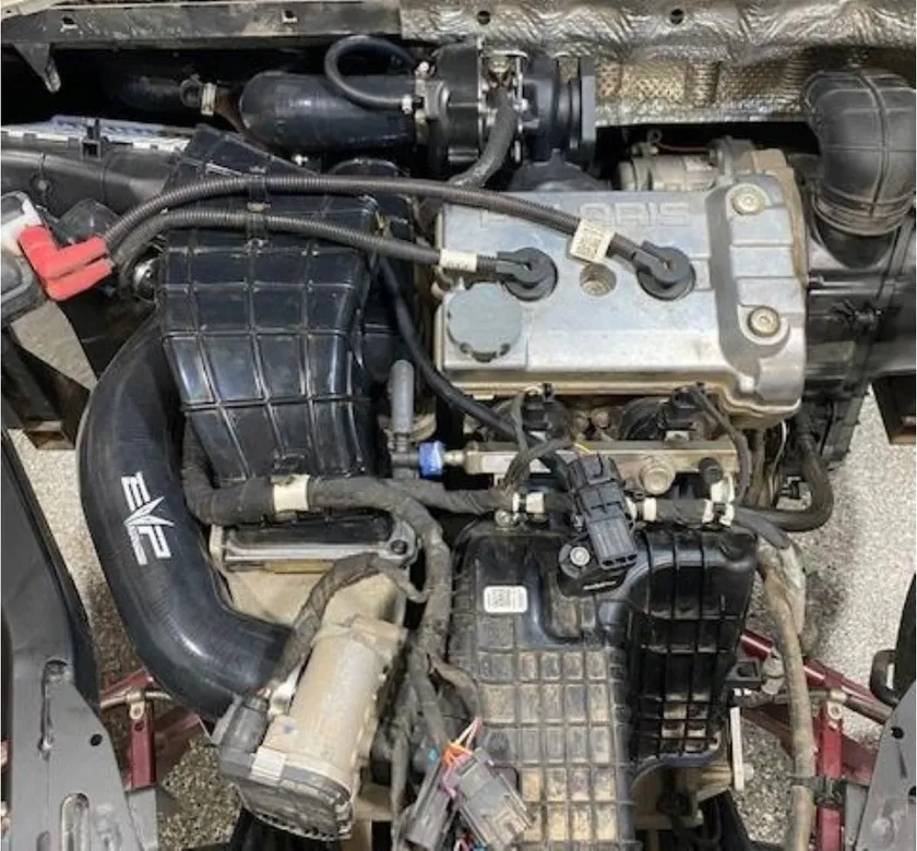
Reinstall back on the CVT housing, reinstall the coils.
- Step 73
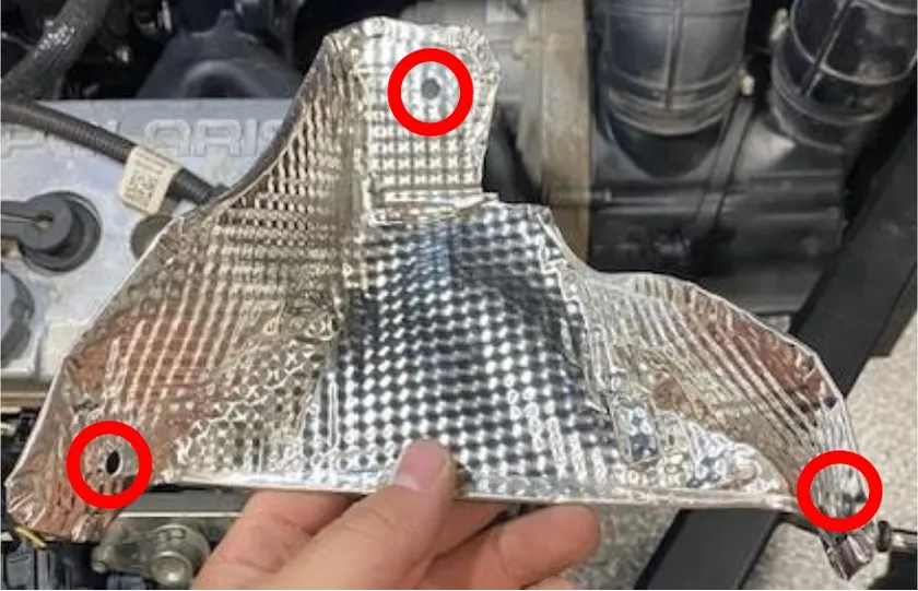
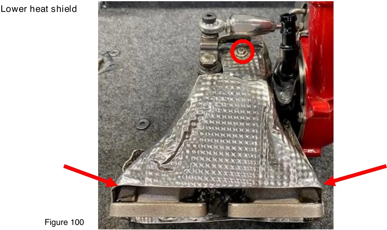
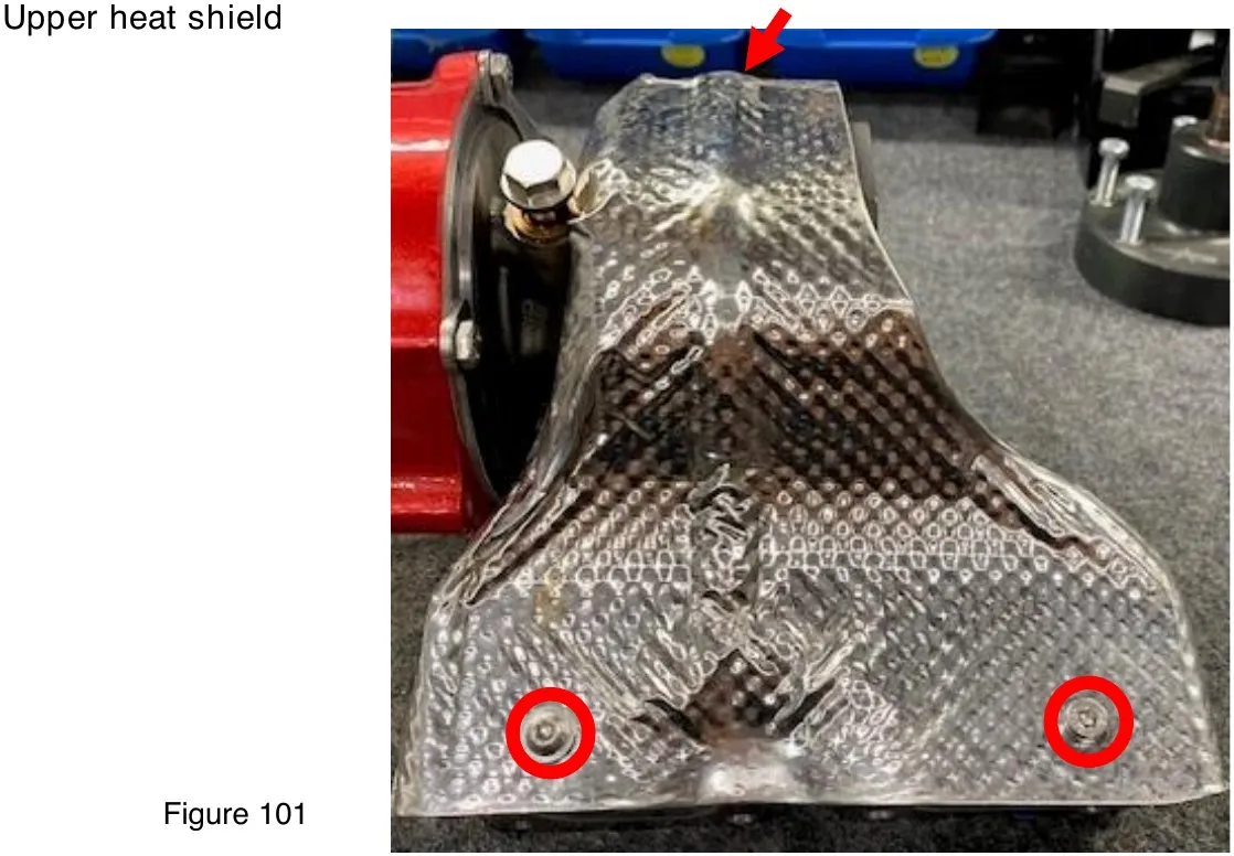
Installing the turbocharger upper/lower heat shields. Below are photos on the heat shields on the bench. Both heat shield has (3) screws, one on the lower heat shield being close to the wastegate rod. This one is difficult to reach in the car. See below.

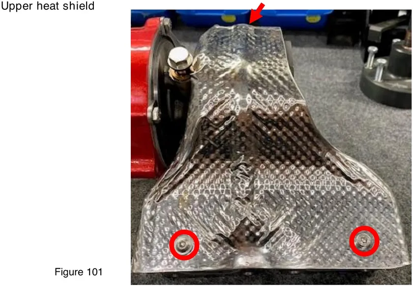
- Step 74
Install the lower heat shield first, use (3) supplied button head screws. It may be easier to place a screw on a ball end Allen wrench and get the hole closest to wastegate turn buckle.
- Step 75
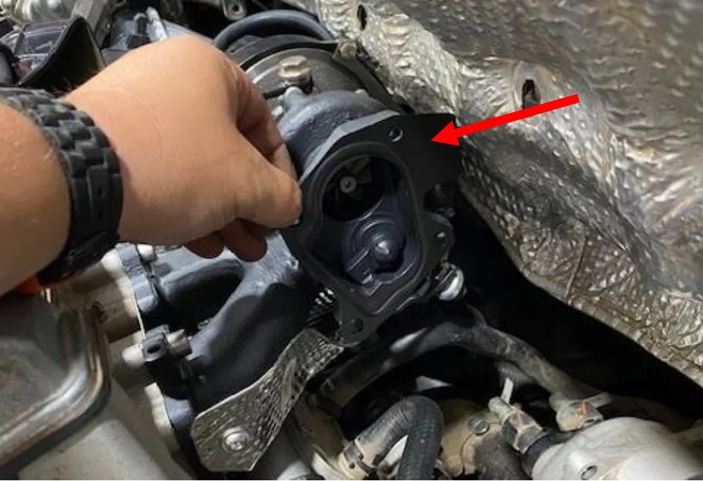
Install the turbocharger to downpipe gasket and downpipe, use supplied stainless hardware supplied. Torque to 16 ft-lb.
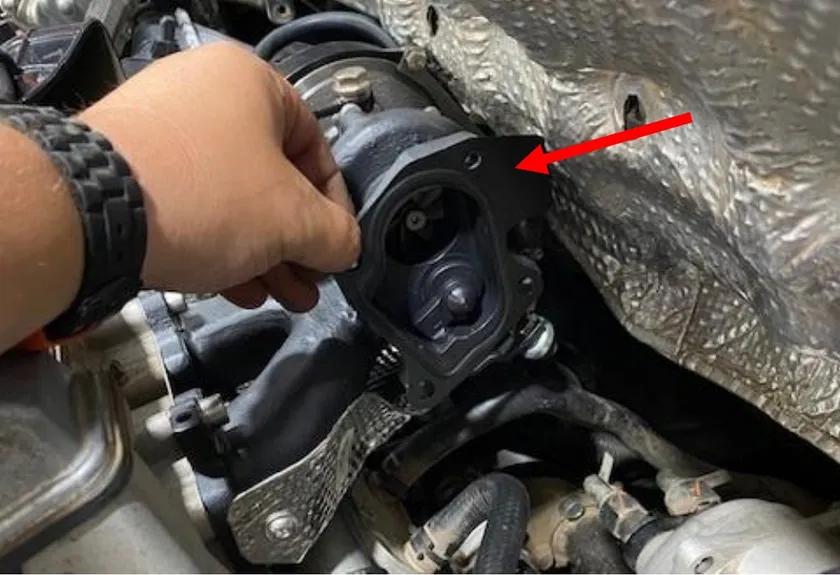


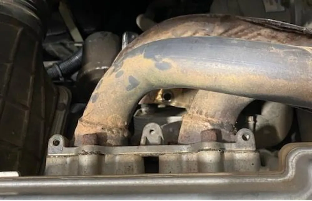
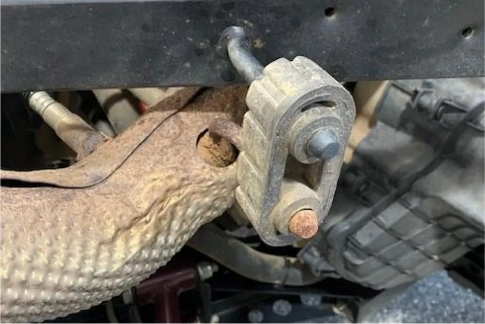

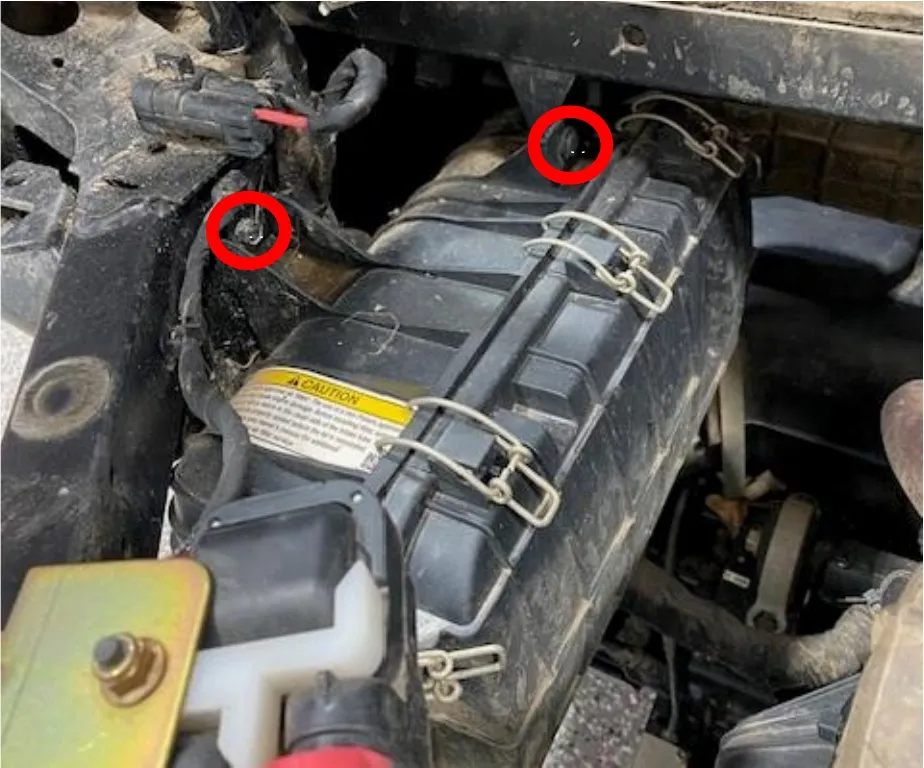
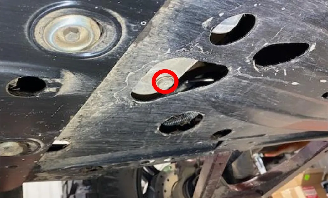

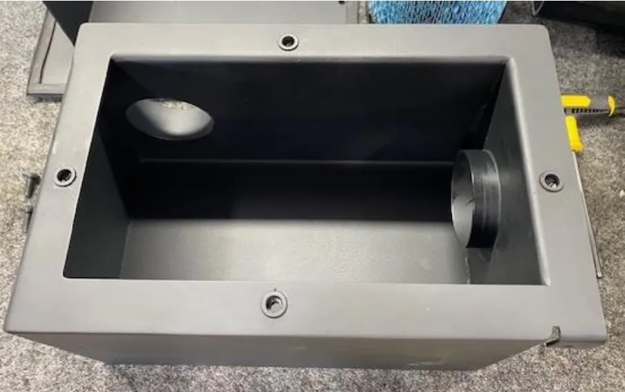
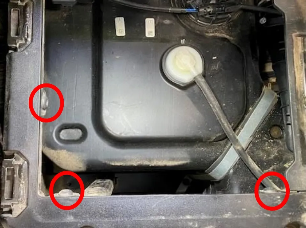
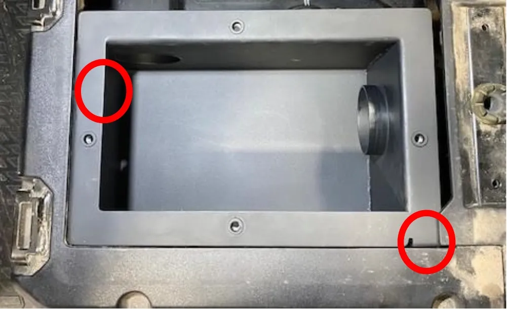
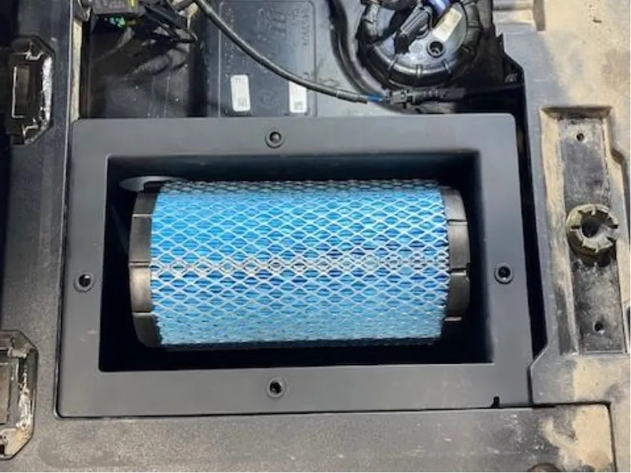

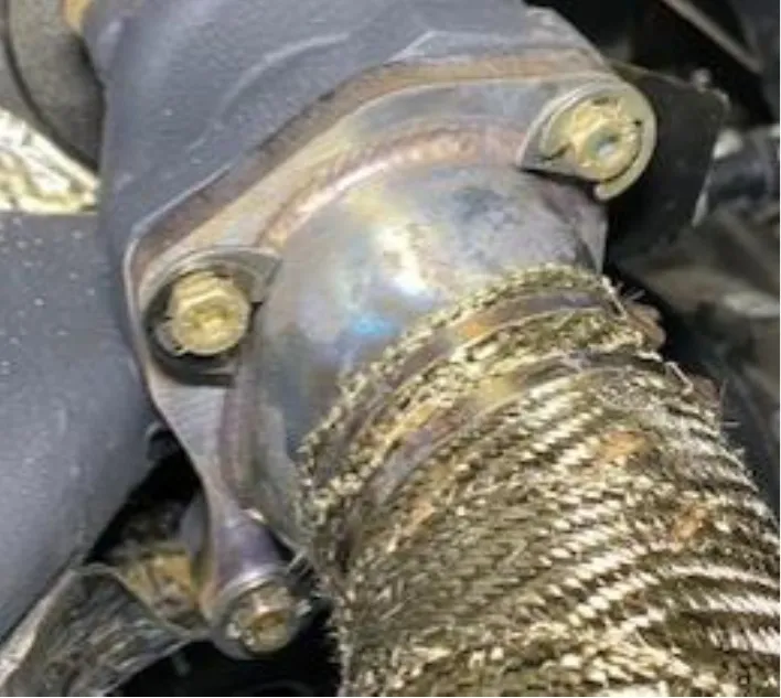
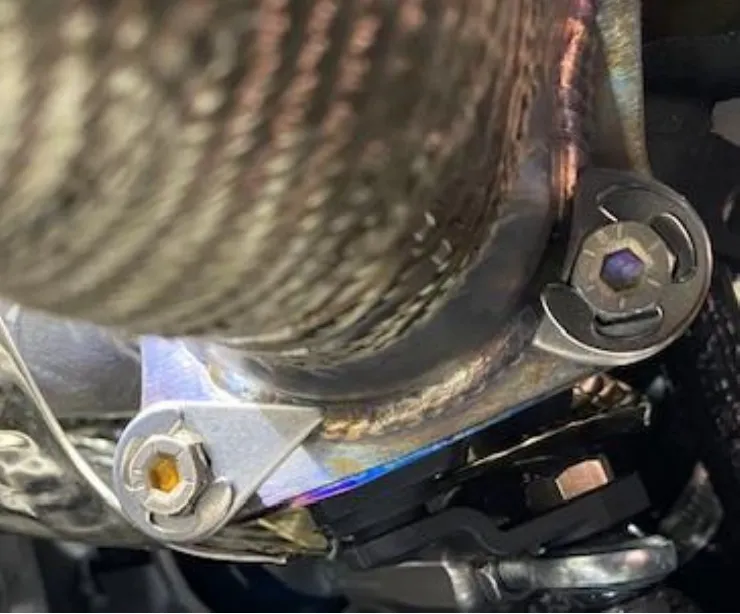
Install the Stage 8 locking fasteners. (3) half-moons and (1) tear drop which will be installed on the lower left bolt.
- Step 76
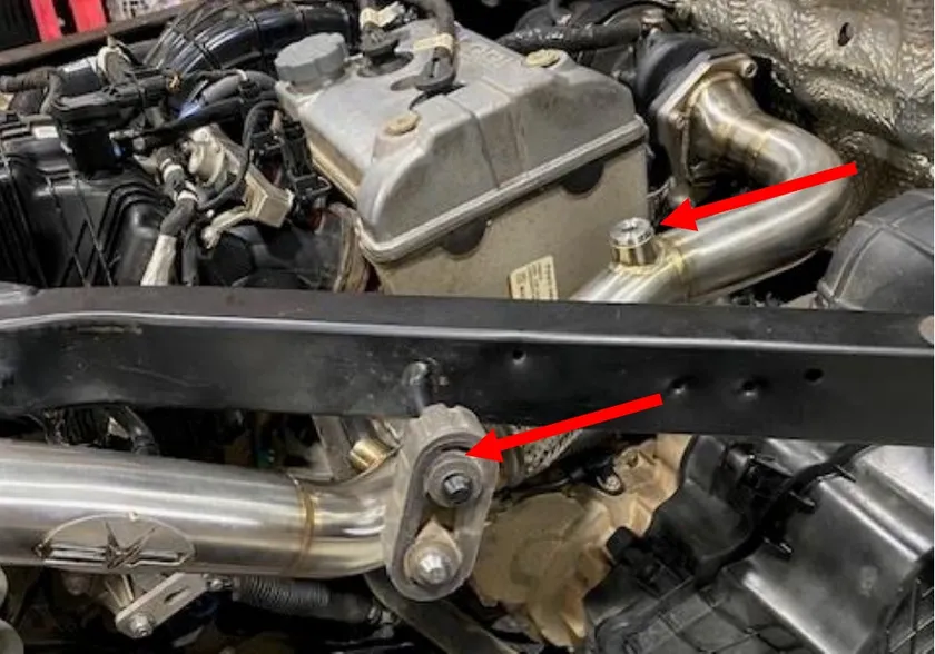
Install the downpipe, reuse the OEM rubber isolator hanger, install anti-seize on first 02 bung and tighten down with 8mm Allen.
- Step 77
Install supplied exhaust gasket donut, install exhaust screws and springs. If your old screws are trashed, please get new ones. Tighten them in steps until both are bottomed out on the head pipe flange.
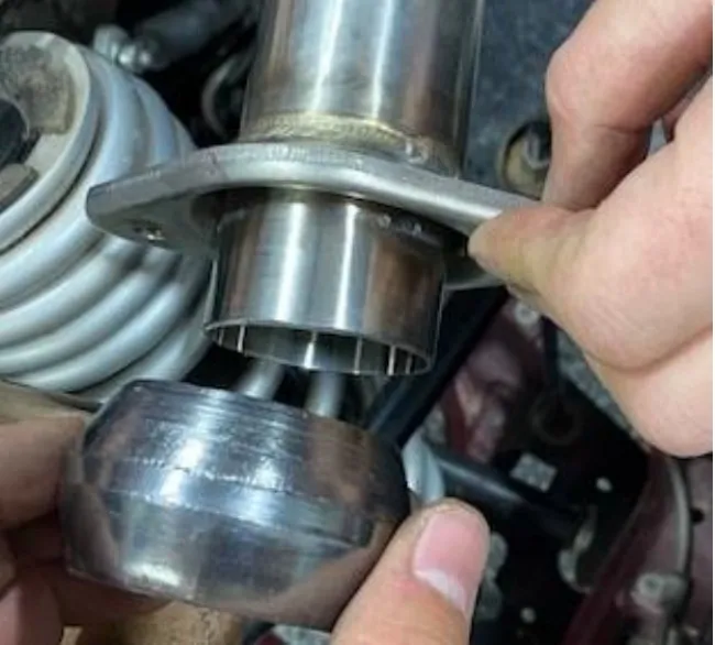
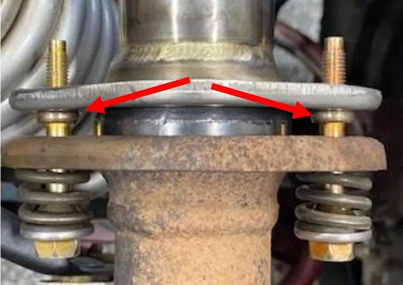
Fig. 106 - Step 78
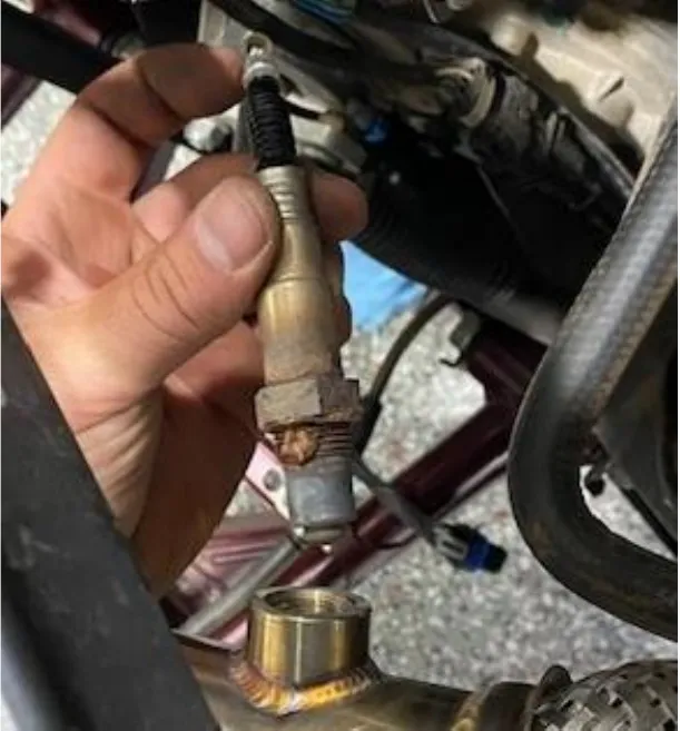
Apply anti-sieze to the 02 sensor threads, install it into the second bung on the pipe. Tighten with a 22mm and plug in the connector.
- Step 79
Install the upper heat shield and (3) supplied screws. Push up on the firewall heat shield to gain access.

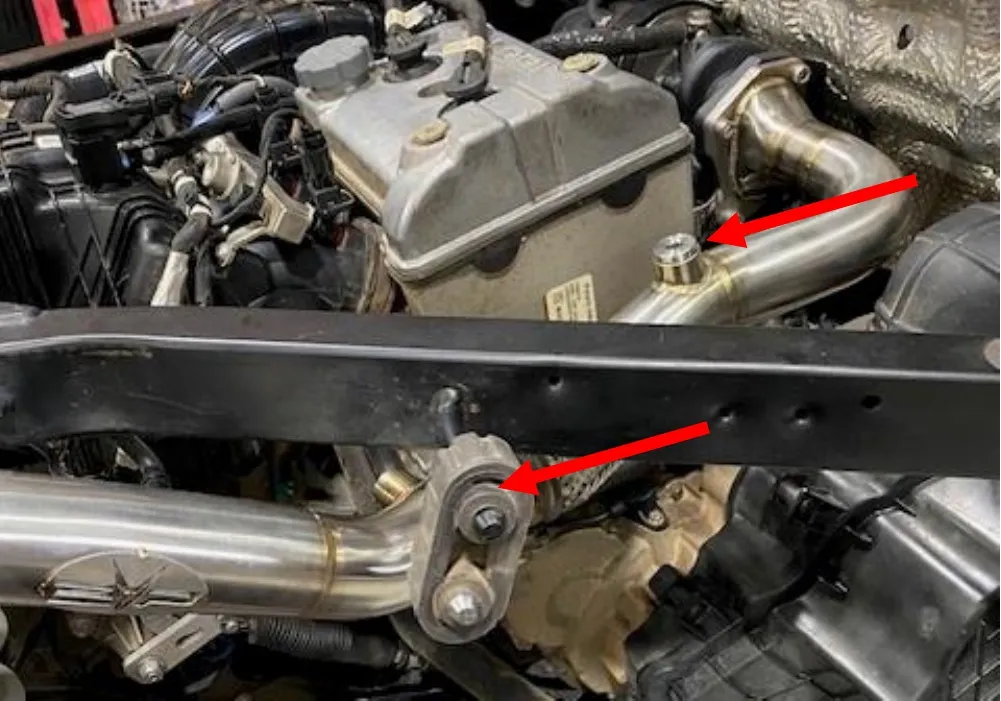
- Step 80
Wipe down the entire exhaust system with brake cleaner and alcohol. Install the heat blanket and springs onto the head pipe.
Notethis will smoke for some time during first couple startups.

- Step 81
Find the rear seat mounting hardware.

- Step 82
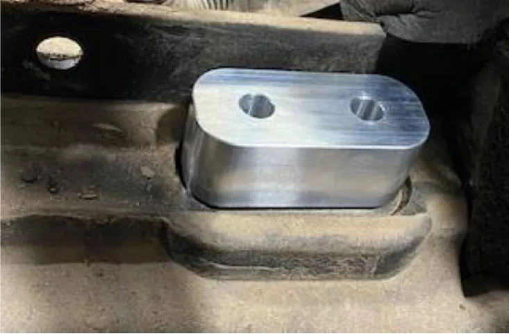
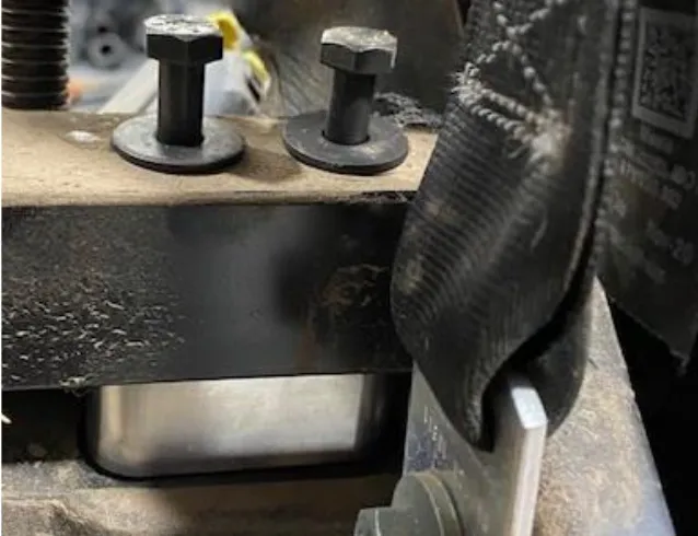
Install the billet blocks on the rear seat frame. Place the rear seatbelt mount on top of the billet block, install new hardware and fasten down.
- Step 83
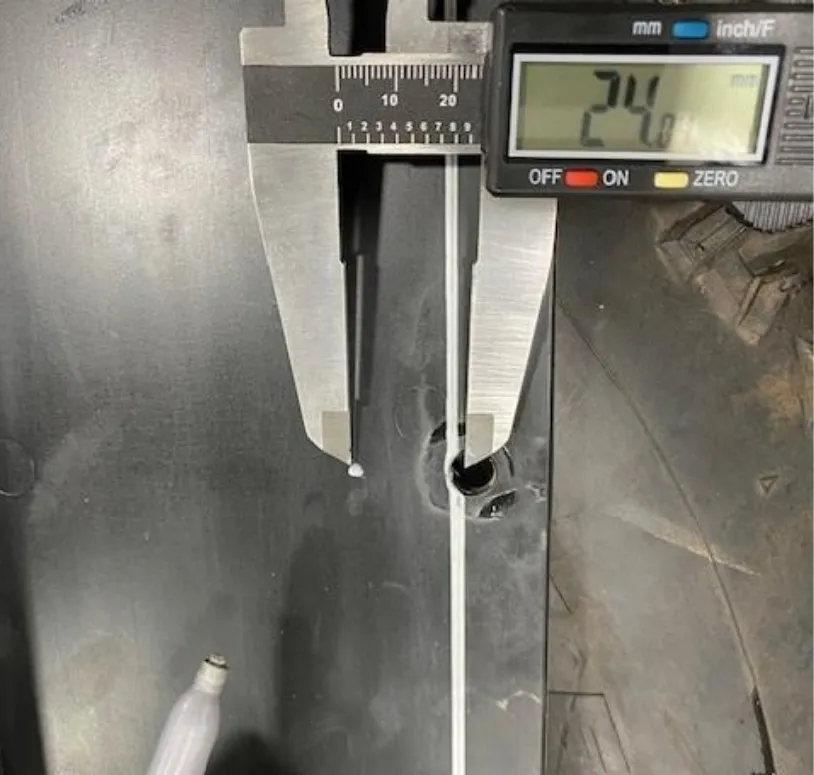
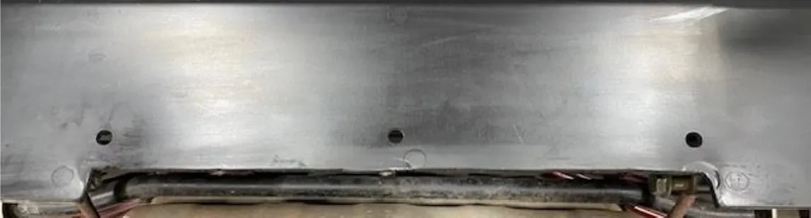
Clean the rear firewall outside. You will be drilling 24mm upwards, center to center on all (7) lower holes. Use a 3/8” drill bit, silver sharpie, and a measuring device.


24mm center to center, going upwards.
- Step 84
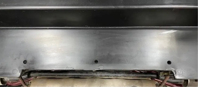
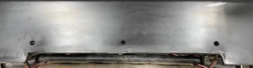
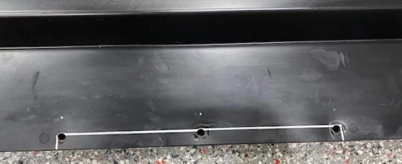
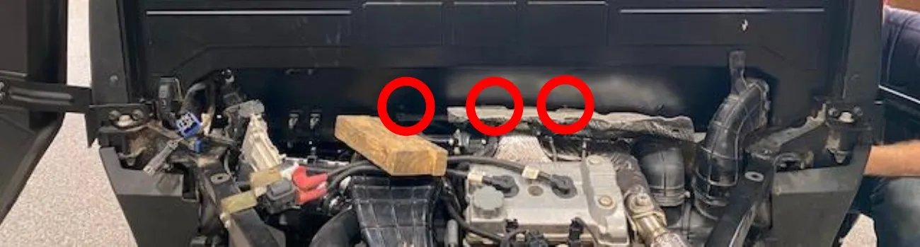
On the middle (3) holes, you will be cutting out the tops of all three holes, and the outsides of two. As seen in figure 106, here is a close up.

- Step 85
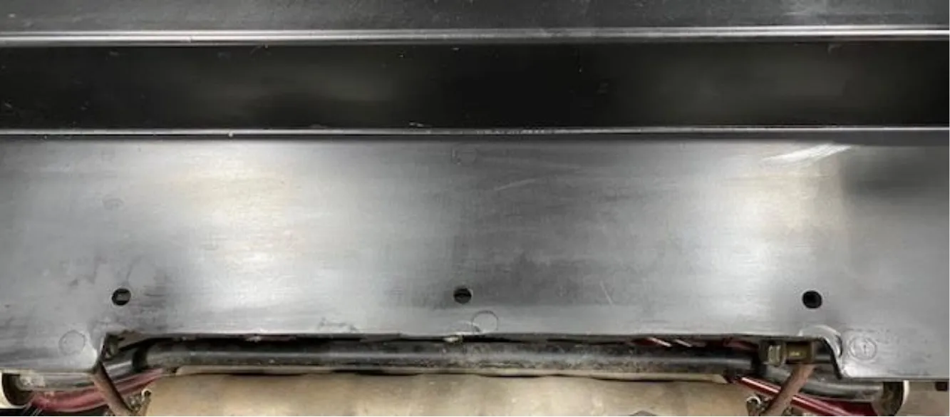
It works best to use a Dremel, sandpaper, round all corners, and use a flame at the end to smooth out the plastic.
- Step 86
Below is the finished cut and drilled firewall.
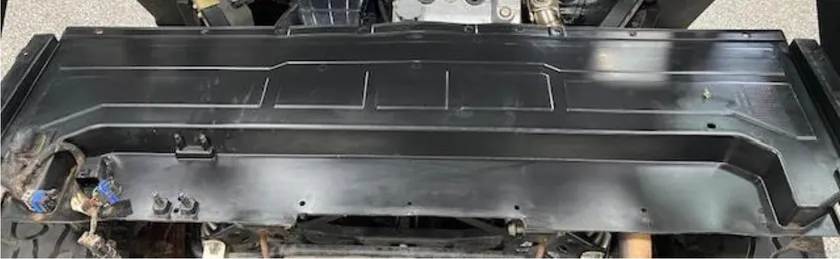
- Step 87
Reinstall rear carpet/soundproof material and (6) push darts.
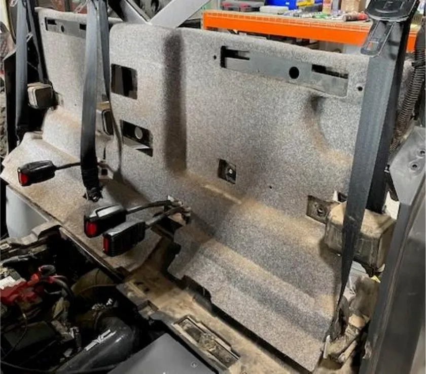
- Step 88
Install the rear back pads, clip in the tops and reinstall (6) screws for plastic from the backside.
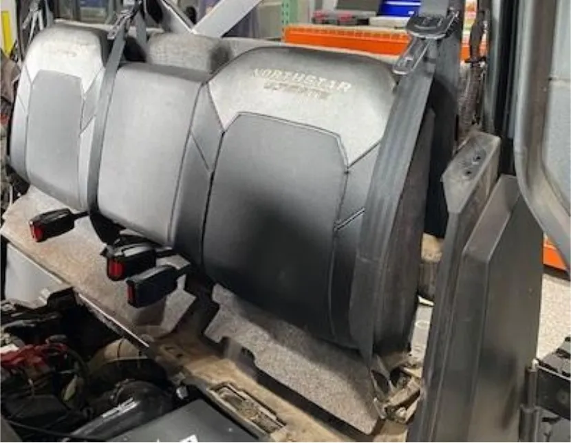
- Step 89
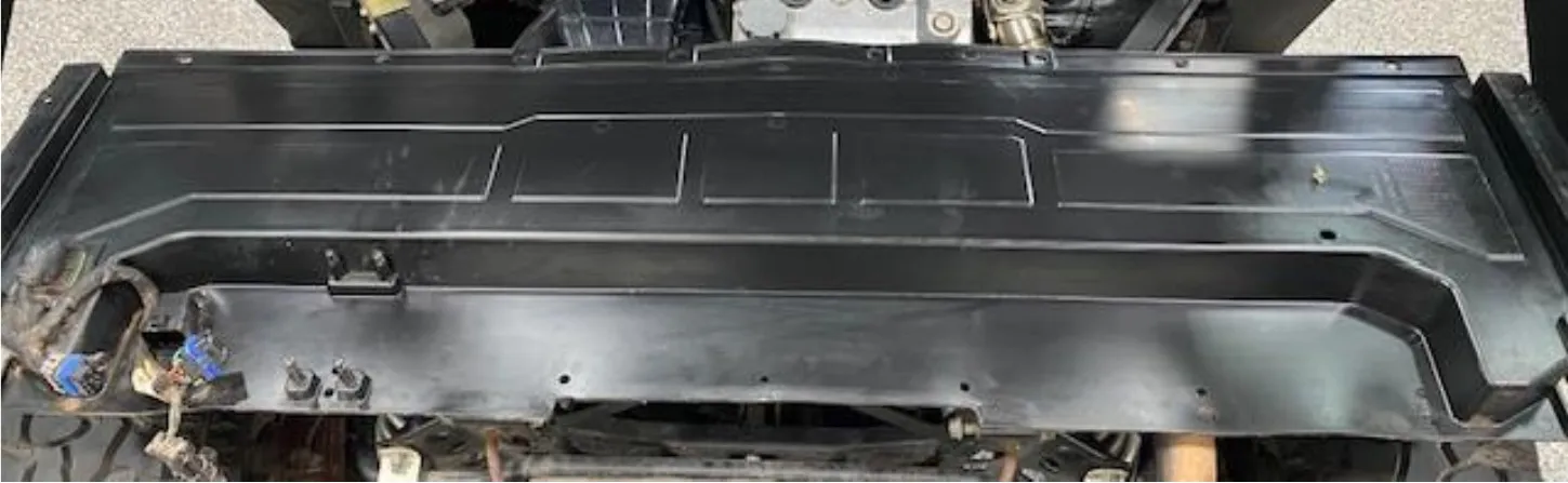
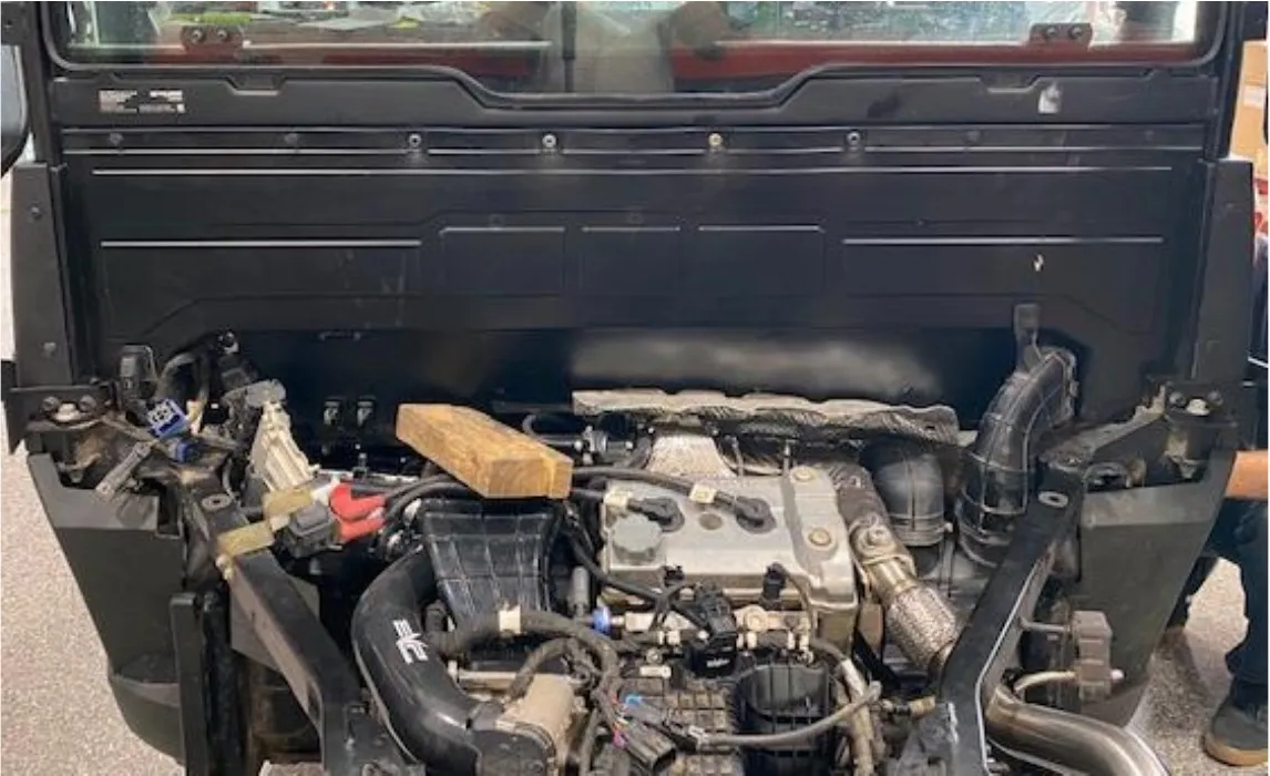
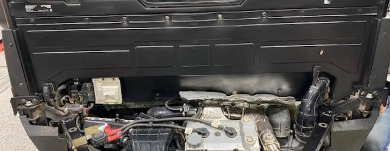
Fold the OEM heat shield back down to the original 90-degree bend. Slide the bottom of the firewall into place. The (3) holes that were cut out will fit around the turbocharger. Reinstall the yellow connector on the driver side, and re-mount the AC air duct on the passenger side (if equipped).
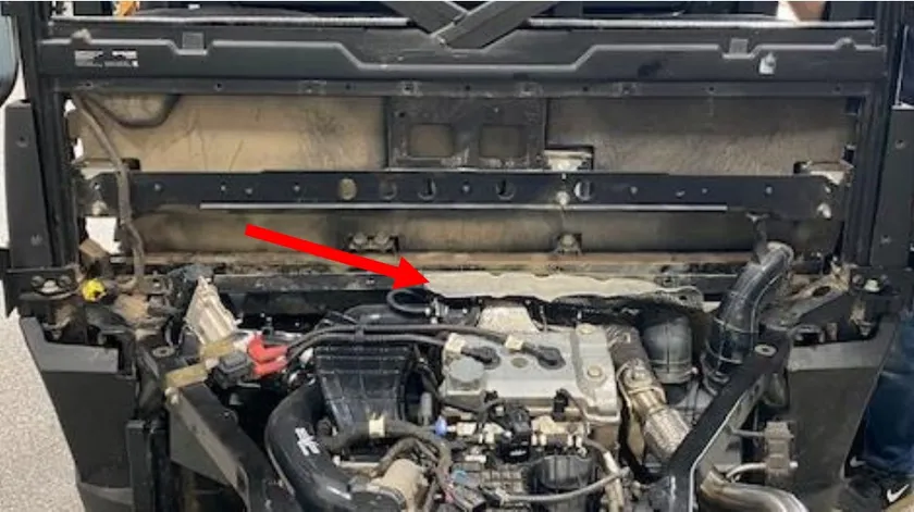
- Step 90
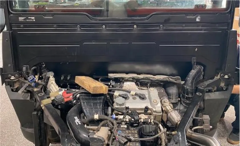
Install all upper hardware screws & push darts, hardware for end caps, rear window.
- Step 91
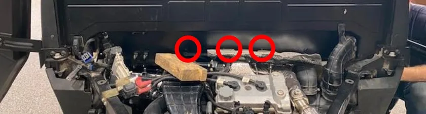
Pay attention to the lower hardware. The (3) holes that got cut away, you must lift up the inner firewall to match these (3) holes, and the hardware will screw into the rear seat mounts. So you have to line up both plastic firewalls, using a second person or pry bar. You will be able to get (2-10mm head) screws through the heat shield. The third hole in the heat shield is not used, even from factory. If you need to, you can make new holes on the heat shield.
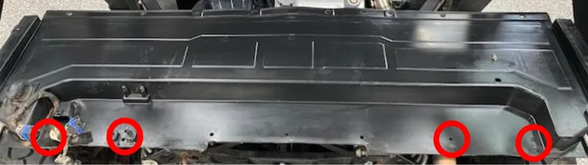
- Step 92
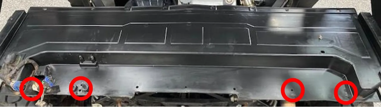
Now that you have the (3) middle holes installed, the (4) holes on the left and right just need to be drilled out with the 3/8” drill bit. You already have the outer firewall drilled; you just need to drill through those holes into the inner firewall. Be careful not to ruin the threads on the seat belt bar. Install (4) T-40 screws.
- Step 93
Reinstall all relays, push darts, and ecu to the firewall.
Noteonly reinstall the top (2) ecu screws. The bottom (2) will not be reused.


Reinstall any zip ties were cut.
- Step 94
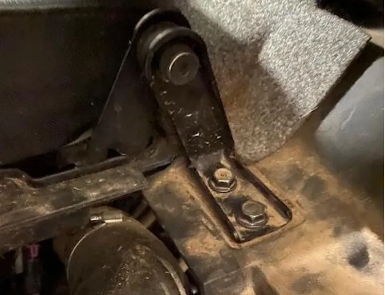
Reinstall the lower rear seats. ONLY one tray will be reused, since the airbox is taking up space. You may need to apply some pressure to this bracket and hardware to get started. Reinstall the shock as well.
Procedure
Steps Before Starting
- Check oil level whether you changed oil or not.
- Make sure the downpipe is wiped clean of all fingerprints
- Correct fuel is drained and added into the fuel tank, 91 or higher octane.
- Correct tune file was already loaded onto the ECU.
- Keep the rear box off for initial start up
- Clutching is already done
- Unplug injector connectors, turn the vehicle over a few times. This will build oil pressure.
- Re-connect injector adaptors, start the vehicle and let is run for a few minutes. Check for leaks around the fuel rail, oil filter adaptor block etc.
- Reinstall bed, connectors etc.
Note
new turbochargers smoke, new exhaust smoke, heat blankets smoke.
Note
Check oil levels again, add if necessary.
Need technical support?
Submit a ticket with your vehicle and what you're seeing, and our support team will get back to you.
