 BUY NOW, PAY LATER. Starting at 0% APR


Fuel Pump For 275 and 310 Kits
Can-Am 2017-2021 X3/Turbo R & 2020 Turbo RR Dynomite 275 & 310
2017-2021 X3/Turbo R & 2020 Turbo RR Dynomite 275 & 310 Turbo Kit
Before you start
Note
Expect 24–48-hour delay from the time you request a tune to when the file is enabled. Please create your Maptuner account before starting the project.
| Level | Tunes | Boost (psi) | Spark Plug Gap | Waste Gate (psi) | Engine HP |
|---|---|---|---|---|---|
| DM-275 | 91, 100 | 24 | .016 - .018 | 6.5psi | 275 (100) |
| DM-310 | 91, 100, 110, E85 | 29 | .016 - .018 | 6.5psi | 310 (E85 or 110) |
By purchasing this kit, you understand and agree to the following:
This is a high-performance upgrade!!!! Although we have gone through great lengths to build safety into the upgrade turbo kit, the fact is installing any performance upgrade and/or turbo system requires care in both operation and installation. Poor fuel, improper setup or any number of things that are done incorrectly can damage your engine!
- You have likely voided the sound and exhaust emission standards of your country if applicable
- This upgrade is intended for OFFROAD and RACING use only
- This is a performance upgrade which may shorten the life of your engine, especially if installed incorrectly or operated without regard to your instruments
- The fuel requirements must be adhered to!!!! Poor fuel can destroy an engine in seconds!!!
- Evolution Powersports bears no responsibility for damage caused to your vehicle by the installation of EVP products. The warranty on big turbo kits is 30 days from the date of purchase. Evolution Powersports, at its discretion will determine whether a part meets the warranty requirements. In no case is there any warranty from EVP for your vehicle or vehicles drivetrain. Although we have been careful to supply you with the highest quality parts possible, we assume no liability for damage to vehicle or personal injury from installing or using any of our products.
- The installation of this kit is technical and mechanical in nature with many opportunities to make mistakes – mistakes that can be very costly! If you are not qualified to install this kit, don’t do it!! Bring it to one of our qualified installation centers to do the installation.
- This kit will make your vehicle faster, climb higher and accelerate more quickly and take a longer distance to brake than a stock tuned vehicle. If you are not capable of controlling the vehicle with the added performance, do not install the kit.
- High boost is hard on spark plugs – they must be changed frequently. If you experience misfire issues – Gap and replace the spark plugs!
- A full exhaust and clutching are required for this kit and can be purchased separately
In the box
Parts and tools
Parts included with Dynomite 275 Kit
- Maverick X3 Dynomite Direct Replacement Turbocharger
- DYNOMITE DM-275 and DM-310 Install Kit
- Maverick X3 Silicone Charge Tubes with BOV Port
- Maverick X3 Blow Off Valve Kit
- Can Am X3 Injectors – Set of 3
- Maverick X3 Big Intake Outlet with New Silicone Boot
- Maptuner X for BRP Vehicles (Includes Maptuner X and BRP Cable)
Parts included with Dynomite 310 KitDynomite 310
- Dynomite 275 Kit
- Ultra-High Efficiency Intercooler – with Race Core
- Can Am Maverick X3 Head Stud Kit – Set of 8
Parts list for DM-275 and DM-310 Install Kit
- 1Turbo Oil Feed Line
- 12” Fire sleeve for Oil Hose
- 12.5” T-bolt Clamp
- 12.0” T-bolt Clamp
- 127mm Pinch Clamp – Oil Drain Hose
- 120A Fuse
- 2Bosch 4 BAR MAP Sensor
- 1MAP Sensor Adaptor Harness
- 1Fuel Pump Upgrade
- 1Fuel Pump Adaptor Harness with Relay
- 818mm Pinch Clamps for Water Hoses
- 1M8X1.25X40mm Stud
- 1M8X1.25 Copper Flange Nut
- 24” 3/8” Silicone Water Hose
- 3” 3/8” Silicone Water Hose
- 9” 3/8” Silicone Water Hose
- 6” Fire sleeve for Water Hose
- 18” Fire sleeve for Water Hose
- 13/16” Black Nylon Elbow
- 7” 3/16” Vacuum Hose
- 2Brass Splicer 3/8” Hose ID Barb – 3/8” Hose ID
- 13/8” Brass Elbow
Parts list for Rising Rate Fuel System Kit (DM-340 KIT)
- 1Corrugated Fuel Line 13.8”
- 1Bosch 3 BAR Fuel Pressure Regulator
- 1Rising Rate Body and Bracket
- 15/16” Fuel Return Block off Plug
- 11/4” NPT to 5/16” Barb
- 215.7mm Pinch Clamp – Fuel Return Block Off
- 11/4” NPT to 5/16” 90 Deg Barb
- 110.0mm Pinch Clamp – Return Line
- 15/16” Brass T
- 213.3mm Pinch Clamp – Tank Pressure Line
- 11/8” NPT Plug
- 26mm X 1.0 Nutzerts
- 1Circlip 1-7/16 Internal
- 16mm X 1.0 Socket Head Cap Screw
- 2M4X8MM Recessed Screw
- 1In Tank Block Off Hose
- 1Fuel Return Fitting and Grommet
- 1EVP Camshaft set (exchange)
Required tools
- Sockets (7mm, 8mm, 10mm, 11mm, and 13mm)
- T40 Torx
- Side cutter / wire cutter
- 4mm Allen
- 10mm wrench
Required accessories
- EVP or other Full Exhaust
Recommended accessories
- Boost gauge
- AFR gauge
Procedure
Turbo Removal
- Step 1
Remove panel between the seats that allows access to the turbocharger.
- Step 2
Remove and label pressure lines from the boost control solenoid going to the wastegate actuator, intake, and air box.
- Step 3
Remove the worm drive clamp holding the intake tube onto the turbo.
- Step 4
Remove the worm drive clamp on the top of the air box.
- Step 5
Using a 13mm socket remove the 2 bolts behind the driver seat holding the air box to the firewall.
- Step 6
Remove the worm drive clamps or t-bolt clamps holding the charge tubes to the intercooler.
- Step 7
Using a 10mm socket, remove the fasteners (4) holding the intercooler in place. Be sure to unplug the intercooler fan. Remove intercooler assembly from vehicle.
- Step 8
Remove the nut on the V-band clamp holding the exhaust onto the turbo.
- Step 9
Remove the worm drive clamps holding the heat shielding on to the mid-pipe. Remove heat shields from mid-pipe.
- Step 10
Remove oil drain line from turbocharger by cutting the OEM clamp.
- Step 11
Remove the charge tube from the turbo outlet.
- Step 12
Remove oil supply line from top of the turbocharger.
- Step 13
Remove the nut securing the water line to the bottom of the exhaust manifold.
- Step 14
Using soft grip vise grips or hose clamps pinch off the soft coolant lines that supply and return water to the turbo.
- Step 15
Remove the OEM clamps holding the soft coolant line to the hard line on top and bottom. Using a side cutter, cut clamps securing soft water lines to the hard lines.
- Step 16
Remove socket head cap screw securing hard water lines to turbocharger and remove the hard line.
- Step 17
Remove bolts securing exhaust manifold heat shields – lower heat shield can be removed. Upper heat shield must stay on until the turbo is loose.
- Step 18
Using a 10mm socket or T40 Torx remove the fasteners holding the exhaust manifold to the engine and remove the turbo from the vehicle.
- Step 19
Remove oil pressure sensor and OEM oil line (be sure to save the copper washers)
Procedure
EVP Turbo Install Installation
- Step 1
Slide supplied fire sleeve over the supplied oil hose. sensor Reinstall oil pressure through the banjo side of the EVP oil supply hose. Re-use copper washers (install a copper washer on both sides of the banjo fitting).
- Step 2
Install the provided stud into the top hole of the center exhaust port, thread stud in and back it out one full turn (See Fig. 1)
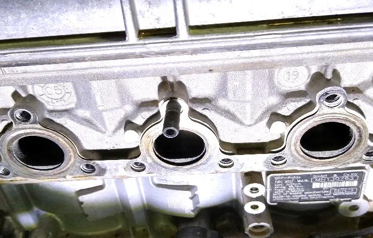
Fig. 1 - Step 3
Reinstall the OEM exhaust gasket and install new turbo charger, reusing OEM fasteners.
- Step 4
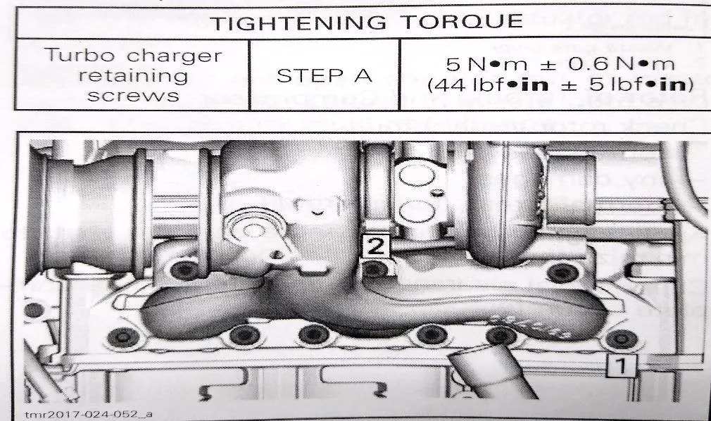
Torque (2) of the retaining screws to 44 in-lb (about 4 ft-lb), following the order shown in Figure 2.
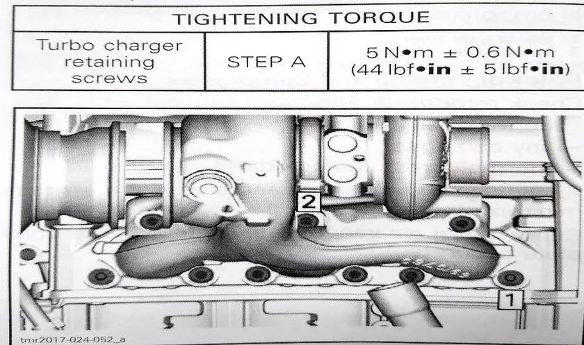
Fig. 2 - Torque5 N•m ± 0.6 N•m (44 lbf•in ± 5 lbf•in)Turbo charger retaining screws, STEP A
- Step 5
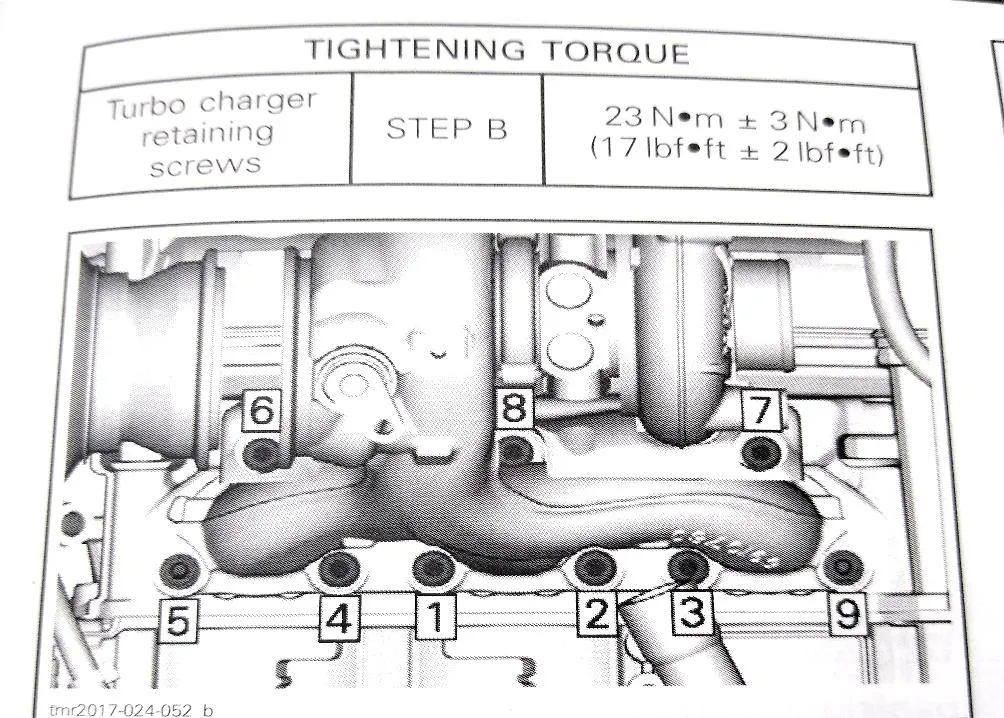
Torque retaining screws to 17 ft-lb, following the order shown in Figure 3. On the final torque sequence take a 4mm Allen wrench and hold stud while tightening copper nut with 10mm wrench as close to 17 ft-lb as you can. (make sure you have at least 2 threads protruding from nut)
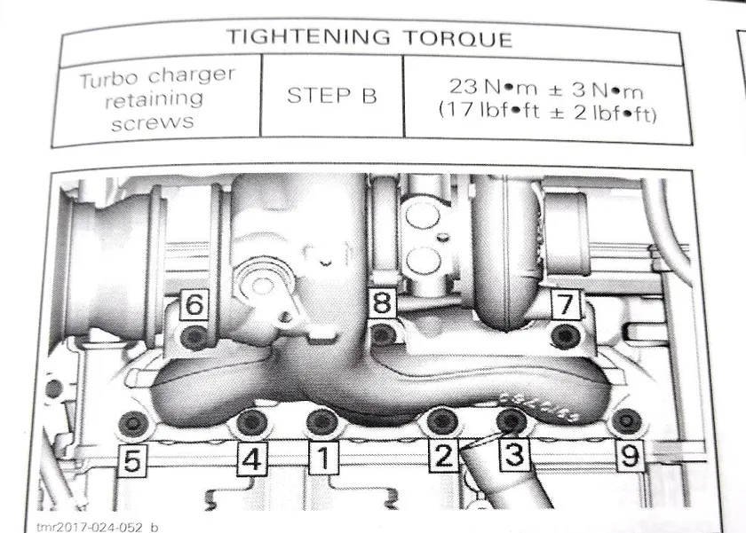
Fig. 3 - Torque23 N•m ± 3 N•m (17 lbf•ft ± 2 lbf•ft)Turbo charger retaining screws, STEP B
- Step 6
Connect the oil line to the fitting on the top of the turbo and tighten.
- Step 7
Use a 27mm pinch clamp to secure the oil line onto the turbo charger.
- Step 8
Using the provided 24” coolant line with fire sleeve and 3/8 brass fitting, connect the supplied line to the lower coolant line on the passenger side. Use an 18mm pinch clamps to secure. Be sure to route the coolant line between the oil drain and motor.
- Step 9
Connect coolant lines to the turbo as shown in Figure 4.
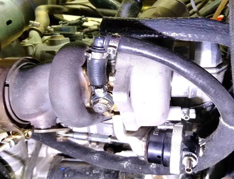
Fig. 4 - Step 10
Cut 4” off existing upper coolant line. Using the supplied 9” coolant line with fire sleeve, connect line to the existing coolant line on the top using the supplied brass fitting. Connect line to the turbo as shown in Figure 5. Secure all connections with 18mm pinch clamps.

Fig. 5 - Step 11
Install the new upper charge tube onto the turbo.
- Step 12
Reinstall the intercooler and connect the charge tubes and intercooler fan.
- Step 13
Connect the new V-flow to the air box and reinstall the air box to the firewall. Tighten the clamps on the v-flow. (See V-flow instructions for further detail)
- Step 14
Connect the 3 lines from the boost control solenoid to their corresponding locations.
- Step 15
Reinstall exhaust - be sure to install the EVP supplied heat shield for the turbo exhaust housing. Additional heat shielding may be required. It is up to the customer and/or installer to determine what additional shielding may be required.
Procedure
2018-2020 Maverick X3 AEM High Flow Fuel Pump
Note
it is best to syphon all fuel out of the tank prior to starting this job
Caution
THE FUEL PUMP RELAY HARNESS MUST BE INSTALLED PRIOR TO POWERING UP THE DASH OR STARTING THE VEHICLE – FAILURE TO ADHERE TO THIS WILL DAMAGE YOUR ECU.
- Step 1
Remove plastics covering fuel tank. See picture below for location
- Step 2
Unplug electrical connector going into the top of the pump.
- Step 3
Unhook fuel hose by removing the red clip from the connection. Then push down on the fitting while pushing in on the back side of the fitting – then lift the fitting off the pump assembly.
- Step 4
Rotate pump assembly cap counterclockwise and remove. Remove assembly. (see the pictures for clarification)
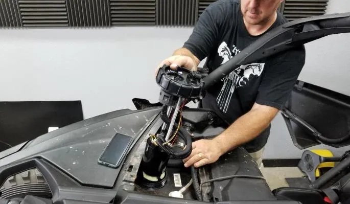 Note
Your fuel pump assembly must be the 172 HP Turbo R or 195 HP RR versions. If you have a 2017 X3 or a 120 Base Model that has not been updated to the Turbo R or RR pump assembly, this must be purchased separately!
- Step 5
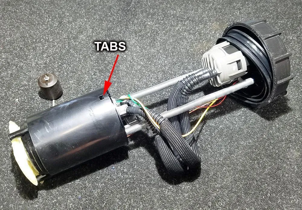
With the fuel pump on a workbench and all the fuel drained out of the pump assembly, press in on the tabs to release the housing covering the tank.
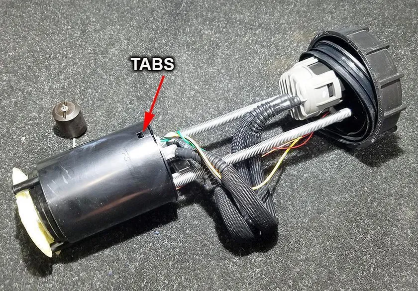
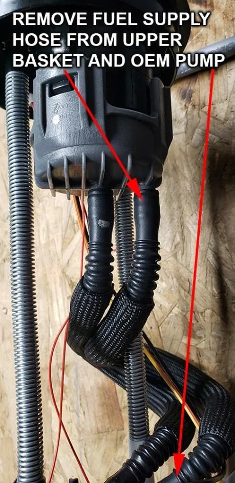
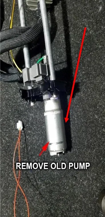
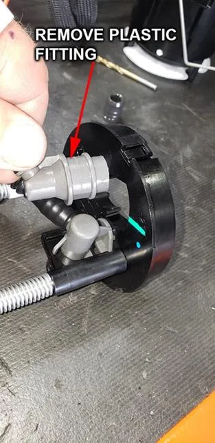
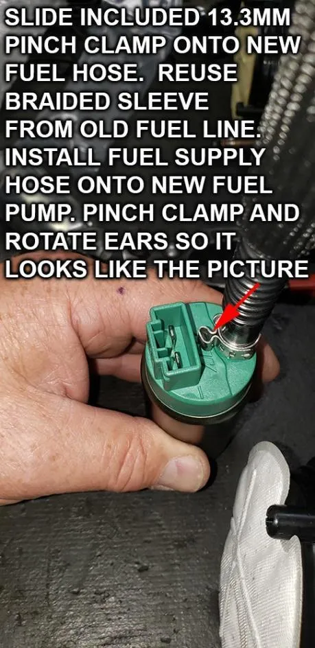

Install fuel pump assembly back into tank in the reverse order from its removal.
- Step 9
Install the EVP supplied fuel pump into the plastic housing that was removed in step 5. Make sure the pump is oriented and fitted correctly into the bottom of the housing - when properly oriented, the pump will drop into place and it will not rotate.
- Step 10
Plug the electric connection into the pump.
- Step 11
Carefully align the tabs and reinsert the cap into the housing – do not force it – if it does not fit in with moderate pressure, something is not correct – recheck. See picture below of fuel line and electrical connection.
- Step 12
Reinstall pump assembly.
- Step 13
INSTALL EVP PLUG N PLAY FUEL PUMP RELAY HARNESS
- Step 14
Connect the yellow wire with the ring terminal and the relay to one of the bolts that secure the fuel pump protector strap to the frame. Make sure the ring terminal is grounded to the frame.
- Step 15
Replace OEM fuel pump fuse with the supplied 20 amp in location F5.
Setup
Clutching
Note
Clutching for 275-310 kits must be adjusted for an 8400-8600 RPM shift out. THIS IS VERY IMPORTANT!
Note
Running a 91-octane tune clutching must be adjusted to 8100 RPM shift out.
Setup (optional)
Launch Control
Note
If Launch Control has been purchased as part of this kit, your engagement RPMs MUST be raised to at least 2600 RPMs but preferably 3000 RPMs. The reason is big turbos require more energy to spool and it takes more RPMs to generate enough heat. Although Launch Control will work at 2600 RPM, it cannot build more than a few lbs of boost at 2600. At 3000 RPMs, 7-8 lbs of boost at sea level and modest air temperatures is possible.
Emissions notice. This product is exempt from the emission standards and related requirements of 40 C.F.R. § 1051 as provided by 40 C.F.R. § 1051.620, and California law [e.g., vehicle code §§ 27156 and 38391]. This product is sold only for use in connection with EPA certified, purpose-built, nonroad vehicles used solely for closed course, nonroad competition/racing and not used for any recreational purpose or on public highways or right of ways maintained by and open to the public. This product is sold only in connection with machines that do not fall under state and/or federal noise or emission standards/regulations. Purchasers who/that purchase this product represent and warrant that the product is purchased only in connection with EPA-certified, emission-regulations-exempt and noise-regulations-exempt competition/racing vehicles as interpreted under applicable state and/or federal law.
Need technical support?
Submit a ticket with your vehicle and what you're seeing, and our support team will get back to you.
