 BUY NOW, PAY LATER. Starting at 0% APR


Polaris XP Turbo/S Captains Choice Slip-On Pressure Actuated
XP Turbo/S Captains Choice Slip-On Pressure Actuated
Before you start
The bed of the vehicle has been removed in these pictures to better show the installation.
In the box
Parts and tools
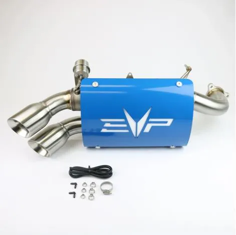
Included parts
- 13/16” Barbed Elbow Fitting
- 124” Hose
- 115.7mm Pinch Clamp
- 211.3mm Pinch Clamp
Required tools
- Pinch Clamp Tool
- Angle Grinder
Procedure
Installation
- Step 1
Remove OEM exhaust.
- Step 2
Install EVP “Captains Choice” Exhaust
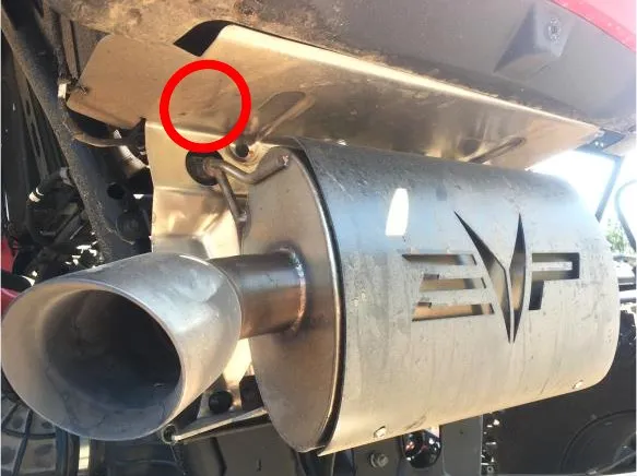 Note
Factory heat shield will need to be trimmed or removed to install the exhaust. It is recommended that the heat shield is left in place and trimmed around the actuator valve. Some customers prefer the look of no heat shield. The location that will need to be trimmed is circled in the following picture.
- Step 3
Remove rear access panel to the top of the engine.
- Step 4
Remove the recirculation valve from factory charge tube.
- Step 5
Disconnect MAP Sensor electrical connection.
- Step 6
Loosen both front and rear T-bolt clamps.
NoteThese will be reused without the springs.
- Step 7
Remove OEM charge tube being careful not to damage the OEM MAP sensor, wiring, or vacuum hoses (it may be easier to remove the bed bolts and shim the bed up with a 2x4 for additional clearance).
- Step 8
Remove MAP sensor from OEM charge tube by unscrewing the T25 securing bolt.
- Step 9
Install MAP sensor into the EVP charge tube. Secure using the M6X12 mm bolt.
- Step 10
Install the OEM T-bolt clamps without springs onto the respective ends of the charge tubes. Install the EVP charge tube onto the OEM intercooler first, then install front end onto the turbocharger and tighten T-bolt clamps.
- Step 11
Slide the supplied 32 mm worm drive clamp onto the BOV port and install BOV or diverter valve. The clamp may need to be opened wider than received in order to fit correctly. Tighten clamp.
NoteIf the fitment is tight, lightly wet and try again.
- Step 12
Reconnect the MAP sensor electrical connection.
- Step 13
Install the 90-degree barb fitting into the small port on the side of the EVP charge tube. If difficult to install, wet with soapy water and retry. If still difficult, ream port hole with a 3/16” drill bit. Slide the 15.7 mm pinch clamp onto the port. Using a side cutter or pinch clamp tool, pinch the ears of the clamp to tighten.
Procedure
Installation for Non-Adjustable Boost Actuated Cut Out Valve
- Step 1
Using the 24” section of hose, slide the 11.3 mm pinch clamp onto the hose and install the hose onto the barb fitting installed in step 13. Tighten clamp.
- Step 2
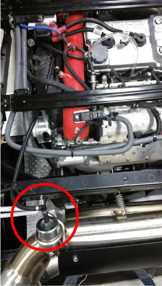
Route the free end of the hose to the actuator valve on the exhaust. An extra elbow connector and clamps are included if your routing requires a sharp bend at the actuator valve. Use if necessary. Slide the supplied green spring clamp onto the hose end and install the hose onto the actuator valve. Slide the clamp onto the actuator valve barb. See section circled with red in the picture.
Need technical support?
Submit a ticket with your vehicle and what you're seeing, and our support team will get back to you.
