BUY NOW, PAY LATER. Starting at 0% APR


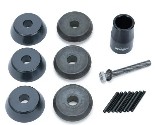
Procedure
Removing and Installing Primary Spring
- Step 1
With a sharpie, mark a straight line down the spider, moveable sheave, and stationary sheave. This will help for reassembly. PDrive clutch has markings on the spider and moveable sheave but it is still useful to mark it.
- Step 2
Remove (6) T40 screws holding the governor cap to the moveable sheave. Slowly let the moveable sheave down without marking up the stationary sheave. See figures 1-2.
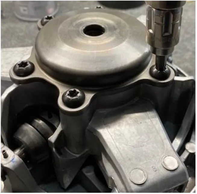
Figure 1 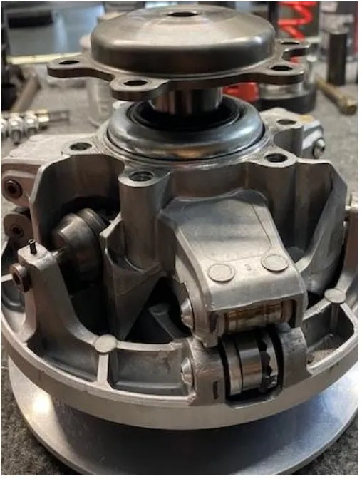
Figure 2 Noteyou may need to use heat to loosen up OE red thread locker.
- Step 3
Apply some grease to the threads of tool Clutch Puller X3. Thread the clutch puller into the clutch, leaving 1/2" gap from bottoming out on the governor cup. Do NOT let the clutch puller stand out past the stationary sheave. See figure 3-4.
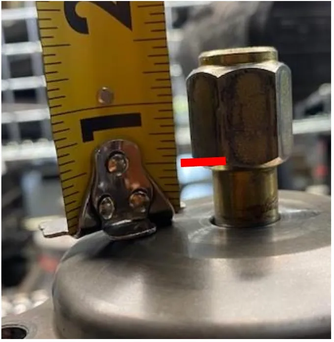
Figure 3 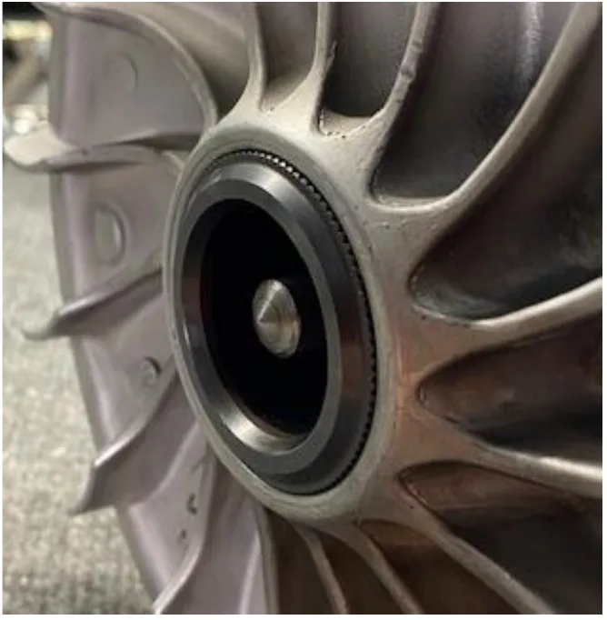
Figure 4 - Step 4
Apply grease to the top of the clutch puller. See figure 5.
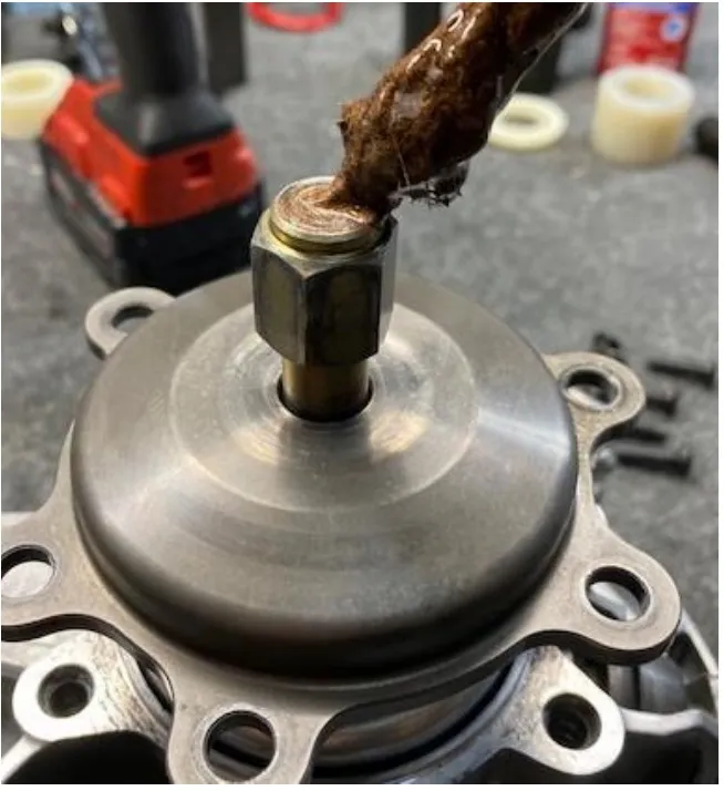
Figure 5 - Step 5
Install the Governor Cup Removal Tool with hardware. (6) M8 bolts and (1) M16 bolt. Slide the moveable sheave up to the governor cup. With a 13mm socket, screw in all (6) M8 bolts. Do not overtighten. See figure 6-7.
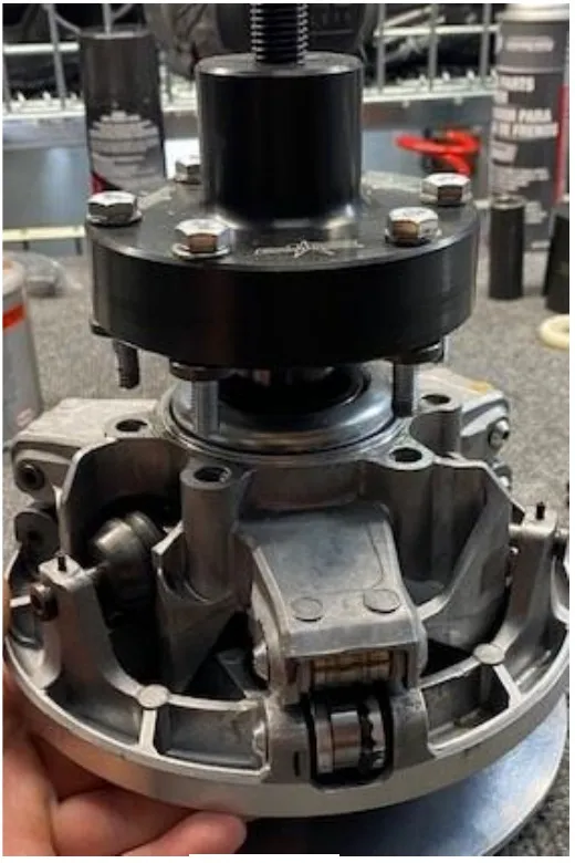
Figure 6 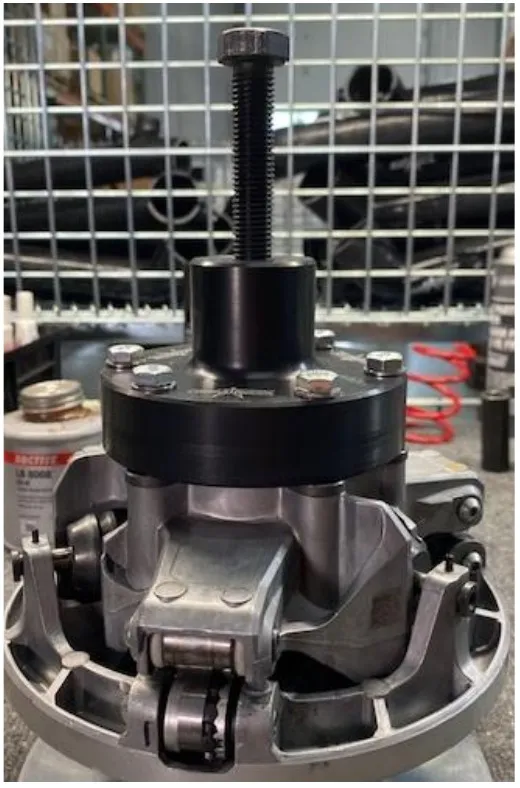
Figure 7 - Step 6
With an impact driver and 24mm socket, screw in the governor cup M16 bolt. This may take some grunt. There will be a loud POP sound when the governor cup pulls off the taper. Loosen the M16 bolt and (6) M8 bolts. Remove the Governor Cup Removal Tool and Clutch Puller from the clutch. The governor cup can be removed from the clutch. See figure 8.
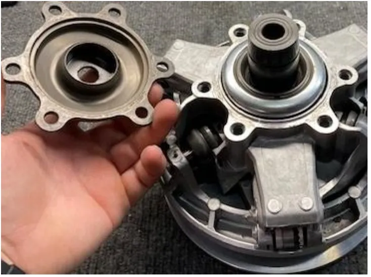
Figure 8 - Step 7
Install the Can Am Primary Clutch Threaded Rod until it bottoms out on the clutch. Install the Circlip Tool with the Nylon Bushing. Thread the Handle for Threaded Rod and compress the spring, taking tension off the circlip. Remove the circlip. See figure 9-11.
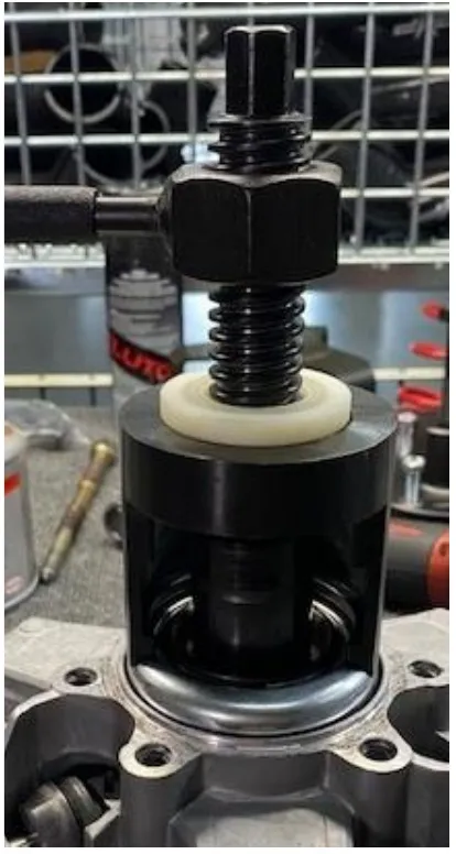
Figure 9 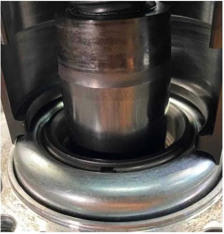
Figure 10 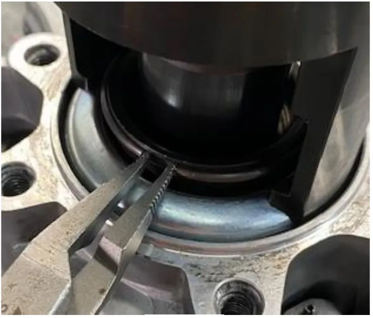
Figure 11 - Step 8
Loosen the handle, decompressing the spring. Remove the Handle and Circlip Tool. Remove the circlip and retaining ring, followed by the spring cup and spring. See figures 12-14.
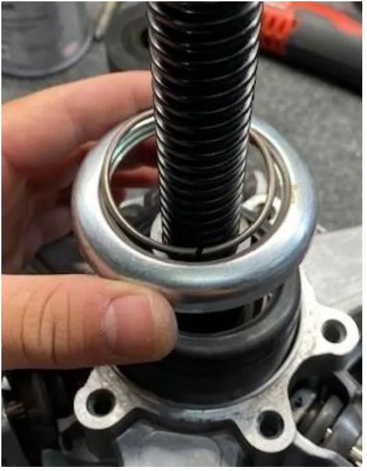
Figure 12 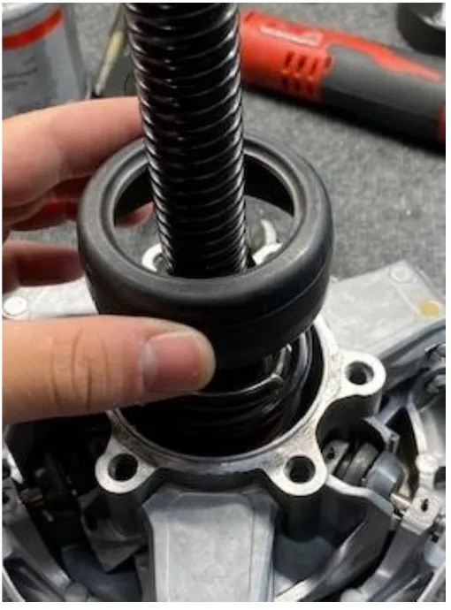
Figure 13 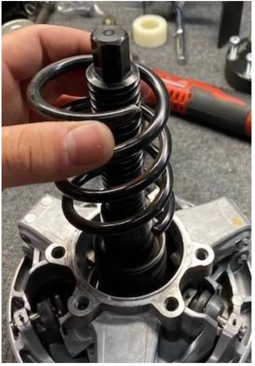
Figure 14 - Step 9
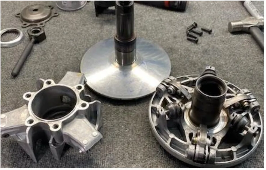
At this time, if you would like, remove the spider from the moveable sheave. Remove the moveable sheave from the stationary sheave. The clutch is completely disassembled for cleaning or replacing the sliding sheave bushings. See figures 15-16
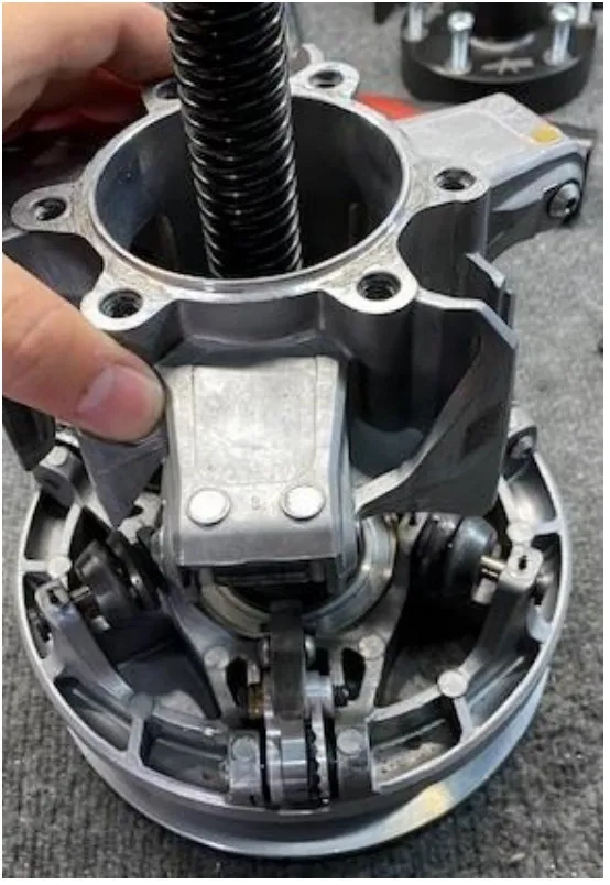
Figure 15 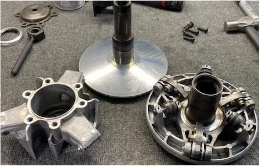
Figure 16 - Step 10
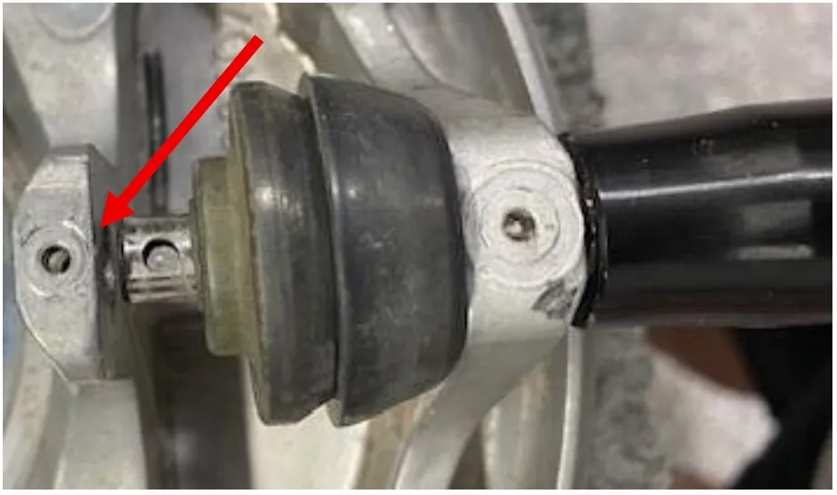
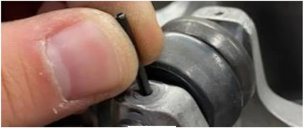
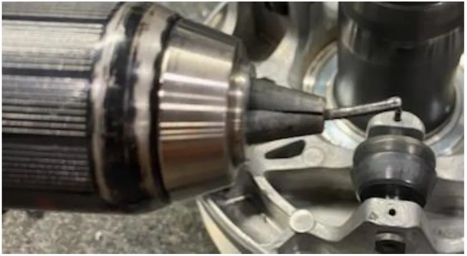
Install a chuck from a drill or a slide hammer onto the spring pins. You don’t need to spin the drill, you can pull up with your hands.
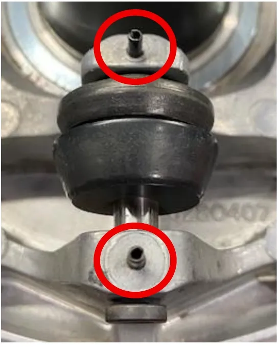
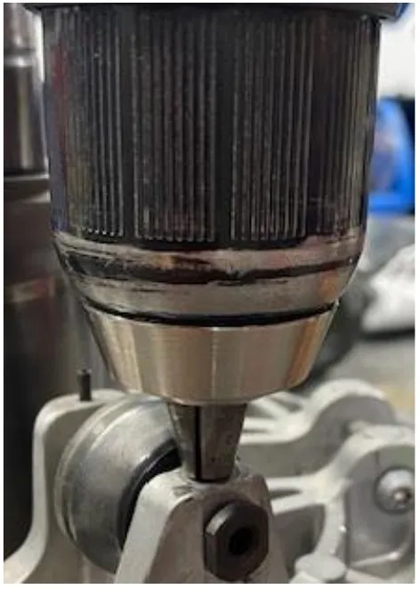
Once spring pins are removed, you can discard them.
- Step 11
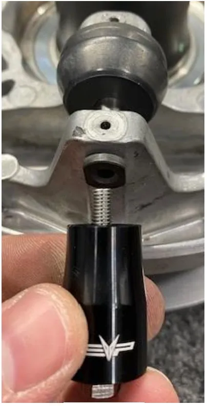
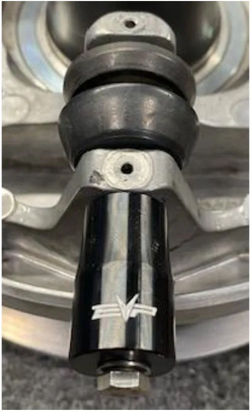
Install the M5-0.8 x 45mm bolt and washer through the billet sleeve. Screw into the end of the roller pin. Use a 8mm socket to start turning the pin out. Don’t use an impact gun, slowly turn by hand. You can use lube or heat to help.
- Step 12
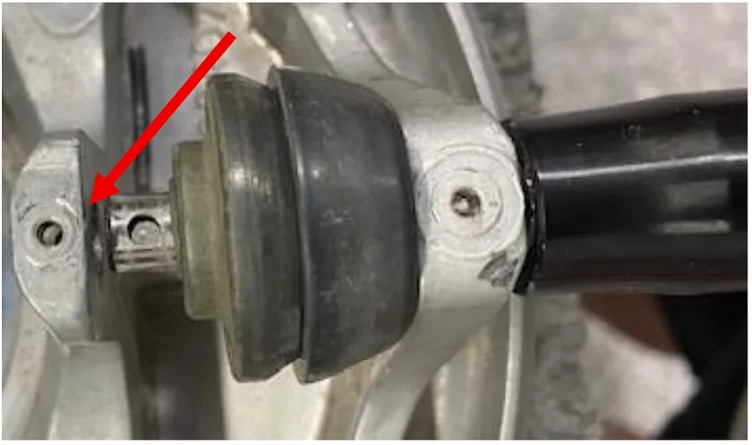
Once the pin passes the first pocket, you can slide the pin and rollers out. The first pocket is tapered.
- Step 13
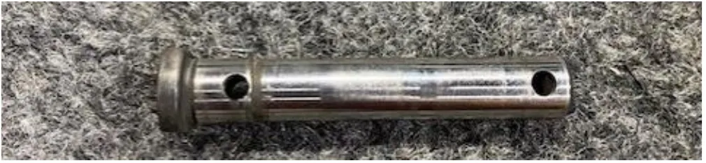
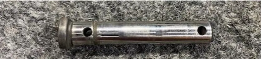
Check the roller pins, if they are worn out or grooved like this one below we recommend replacing. Most of the time the pins are fine and the rollers need replacing.
- Step 14
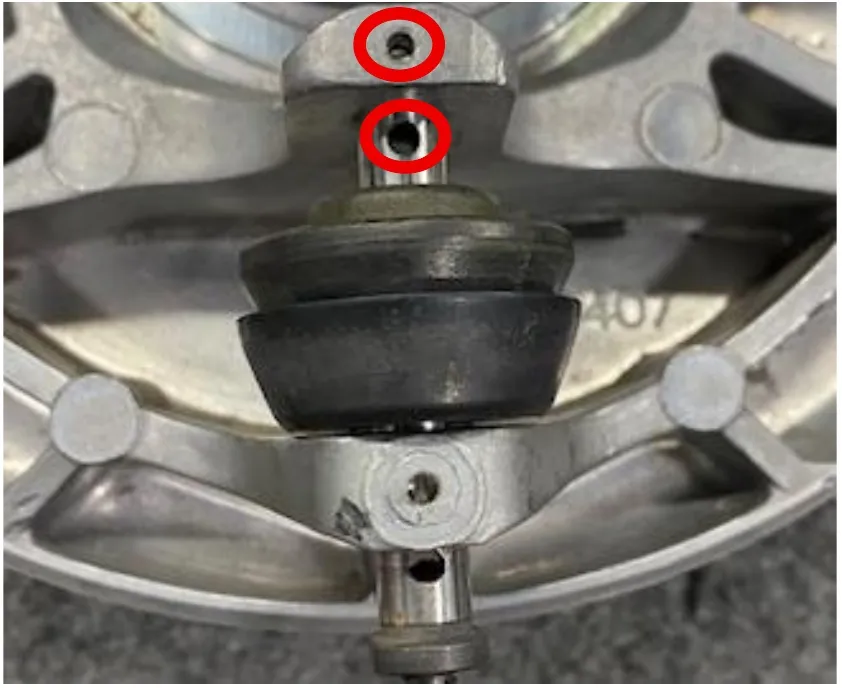
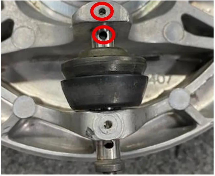
Install the pin with new rollers. Make sure to align the pin holes up with the tower holes. They need to be completely straight. You can use grease or dielectric on the tapered side, tap the pin in with a hammer until the holes are aligned.
- Step 15
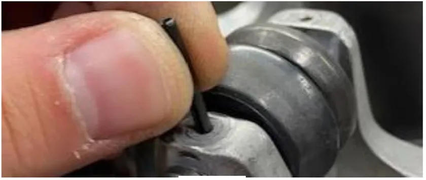
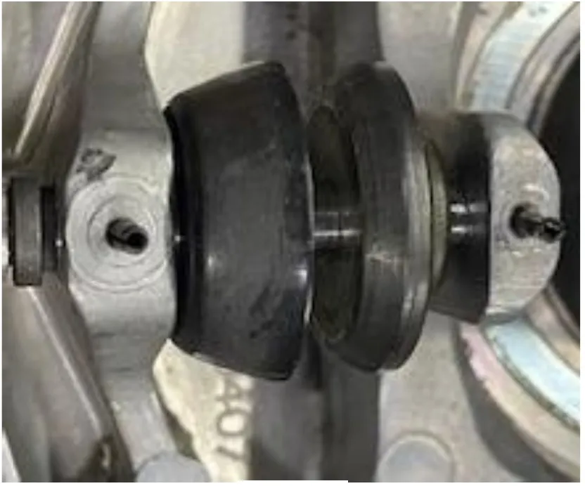
Once the holes are aligned, tap in new spring pins. Make sure not to bottom the spring pins out, or you wont ever get them out again.
- Step 16
Reassemble the drive clutch in reverse order. Make sure your sharpie lines are aligned between the sheaves and spider. You can also see alignment markings on the spider and moveable sheave. See figure 26. When installing the spider, make sure the sliding sheave bushings are split. One on the outside of the tower and one on the inside of the tower. Torque the governor cup bolts to 23 ft-lbs using medium thread locker. Use the Shift-Tek-P Primary Holding Tool when torquing the primary clutch bolt. OE primary bolt torque spec 89 ft-lbs. EVP primary bolt torque spec 110 ft-lbs.
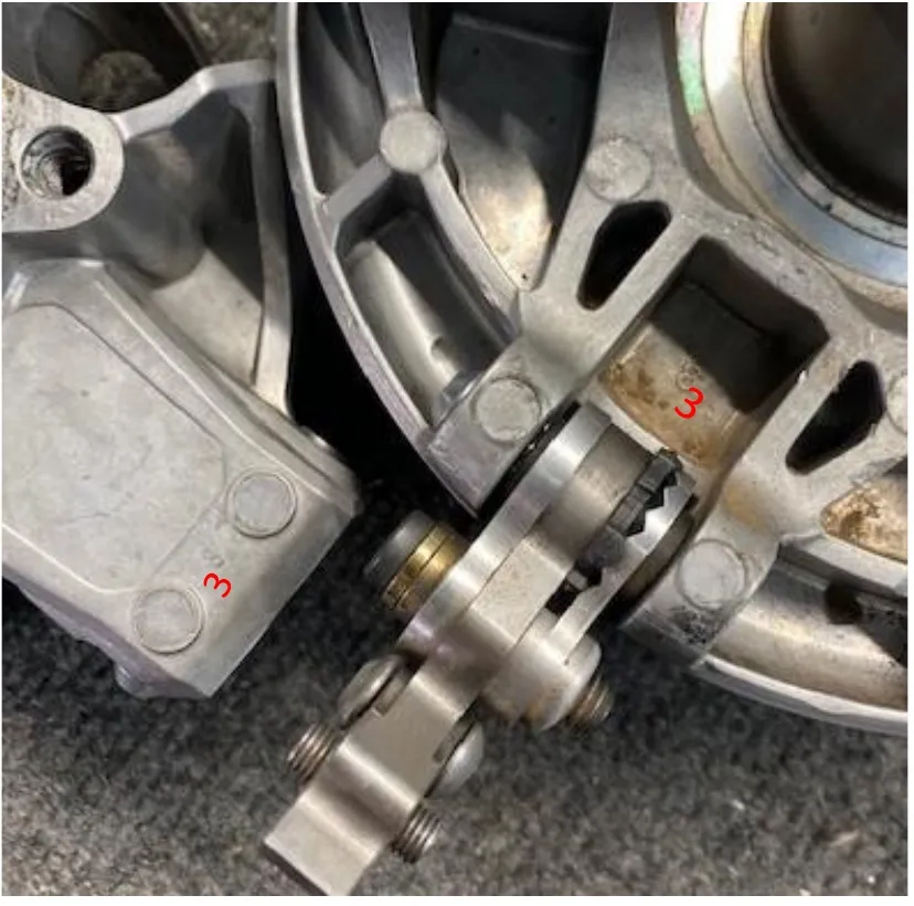
Figure 26