 BUY NOW, PAY LATER. Starting at 0% APR


The illustrations in this document show typical construction of the different assemblies and may not reproduce the full detail or exact shape of the parts; however, they represent parts that have the same or similar function.
Can-Am 2017-2021 Maverick X3 850W Magneto
Installation instructions for the 2017-2021 Maverick X3 850W Magneto on the Can-Am Maverick X3. Parts, tools, and full procedure.
Before you start
Warning
- For safety reasons, this kit must be installed by an authorized BRP dealer.
- This kit is designed for specific applicable models only (authorized BRP dealers will confirm model(s)). It is not recommended for units other than the one (those) for which it was sold.
- Should removal of a locking device (e.g. lock tabs, self-locking fasteners, etc.) be required when undergoing disassembly / assembly, always replace with a new one.
- Torque wrench tightening specifications must strictly be adhered to.
- Always wear EYE PROTECTION AND APPROPRIATE GLOVES when using power tools.
- Unless otherwise specified, engine must be OFF when performing any operation on the vehicle.
- Always be aware of parts that can move, such as wheels, transmission components, etc.
Note
USE TIGHTENING TORQUES IN THE FOLLOWING TABLE IF NOT OTHERWISE SPECIFIED.
| GRADE 5.8 | GRADE 8.8 | GRADE 10.9 | GRADE 12.9 | |
|---|---|---|---|---|
| M4 | 1.8 ± 0.2 N•m (16 ± 2 lbf•in) | 2.8 ± 0.2 N•m (25 ± 2 lbf•in) | 3.8 ± 0.2 N•m (34 ± 2 lbf•in) | 4.5 ± 0.5 N•m (40 ± 4 lbf•in) |
| M5 | 3.3 ± 0.2 N•m (29 ± 2 lbf•in) | 5 ± 0.5 N•m (44 ± 4 lbf•in) | 7.8 ± 0.7 N•m (69 ± 6 lbf•in) | 9 ± 1 N•m (80 ± 9 lbf•in) |
| M6 | 7.5 ± 1 N•m (66 ± 9 lbf•in) | 10 ± 2 N•m (89 ± 18 lbf•in) | 12.8 ± 2.2 N•m (113 ± 19 lbf•in) | 16 ± 2 N•m (142 ± 18 lbf•in) |
| M8 | 15.3 ± 1.7 N•m (135 ± 15 lbf•in) | 24.5 ± 3.5 N•m (18 ± 3 lbf•ft) | 31.5 ± 3.5 N•m (23 ± 3 lbf•ft) | 40 ± 5 N•m (30 ± 4 lbf•ft) |
| M10 | 29 ± 3 N•m (21 ± 2 lbf•ft) | 48 ± 6 N•m (35 ± 4 lbf•ft) | 61 ± 9 N•m (45 ± 7 lbf•ft) | 73 ± 7 N•m (54 ± 5 lbf•ft) |
| M12 | 52 ± 6 N•m (38 ± 4 lbf•ft) | 85 ± 10 N•m (63 ± 7 lbf•ft) | 105 ± 15 N•m (77 ± 11 lbf•ft) | 128 ± 17 N•m (94 ± 13 lbf•ft) |
| M14 | 85 ± 10 N•m (63 ± 7 lbf•ft) | 135 ± 15 N•m (100 ± 11 lbf•ft) | 170 ± 20 N•m (125 ± 15 lbf•ft) | 200 ± 25 N•m (148 ± 18 lbf•ft) |
| M16 | 126 ± 14 N•m (93 ± 10 lbf•ft) | 205 ± 25 N•m (151 ± 18 lbf•ft) | 255 ± 30 N•m (188 ± 22 lbf•ft) | 305 ± 35 N•m (225 ± 26 lbf•ft) |
| M18 | 170 ± 20 N•m (125 ± 15 lbf•ft) | 273 ± 32 N•m (201 ± 24 lbf•ft) | 330 ± 25 N•m (243 ± 18 lbf•ft) | 413 ± 47 N•m (305 ± 35 lbf•ft) |
Installation time is approximately 2.5 hours.
In the box
Parts and tools
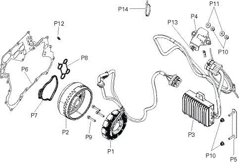
| ITEM | DESCRIPTION | Part number | QTY |
|---|---|---|---|
| P1 | 850W Rotor ass'y | 420686194 | 1 |
| P2 | Stator plate | 420686363 | 1 |
| P3 | Voltage Regulator | 710006824 | 1 |
| P4 | Cable Support | 710007104 | 1 |
| P5 | Voltage Regulator Support | 710006987 | 1 |
| P6 | Gasket (magneto) | 420431640 | 1 |
| P7 | Gasket (water pump) | 420431682 | 1 |
| P8 | Gasket (oil cooler) | 420431870 | 1 |
| P9 | M6 X 30 Socket Head Screw | 205063044 | 3 |
| P10 | M6 Elastic Nut | 233261414 | 4 |
| P11 | M6 Flat Washer | 234062670 | 2 |
| P12 | 7603 DIN Washer | 504082900 | 1 |
| P13 | 173 mm Locking Tie | 293750009 | 5 |
| P14 | 371 mm Locking Tie | 293750018 | 20 |
Required tools
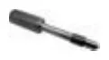
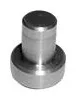
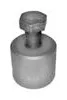
- CRANKSHAFT LOCKING TOOL (P/N 529 036 272)
- CRANKSHAFT PROTECTOR (P/N 529 036 213)
- FLYWHEEL PULLER (P/N 420 976 235)
Procedure
Removing Magneto Cover
- Step 1
Drain engine oil.
- Step 2
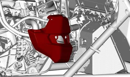
Remove protective cover.
- Step 3
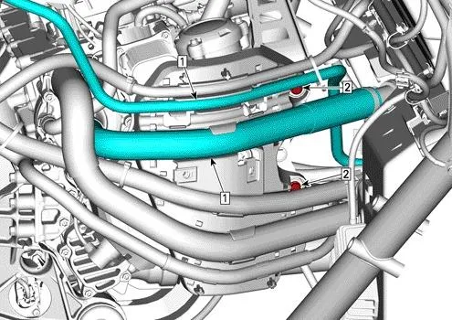
Cut all locking ties securing hoses on the hoses support.

- Step 4
Move fuel and coolant hoses aside, no need to disconnect them as they are long enough to get clearance.
- Step 5
Remove hose support.
- Step 6
Drain coolant by removing the lowest water pump screw. Discard sealing washer.

- Step 7
Disconnect outlet hose from thermostat housing.
- Step 8
Disconnect inlet hose from water pump housing.
- Step 9
Disconnect turbocharger inlet hose from water pump housing. Discard clamp.
- Step 10
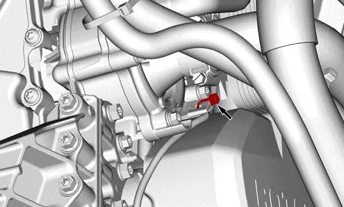
Remove locking ties securing CPS wire.
- Step 11
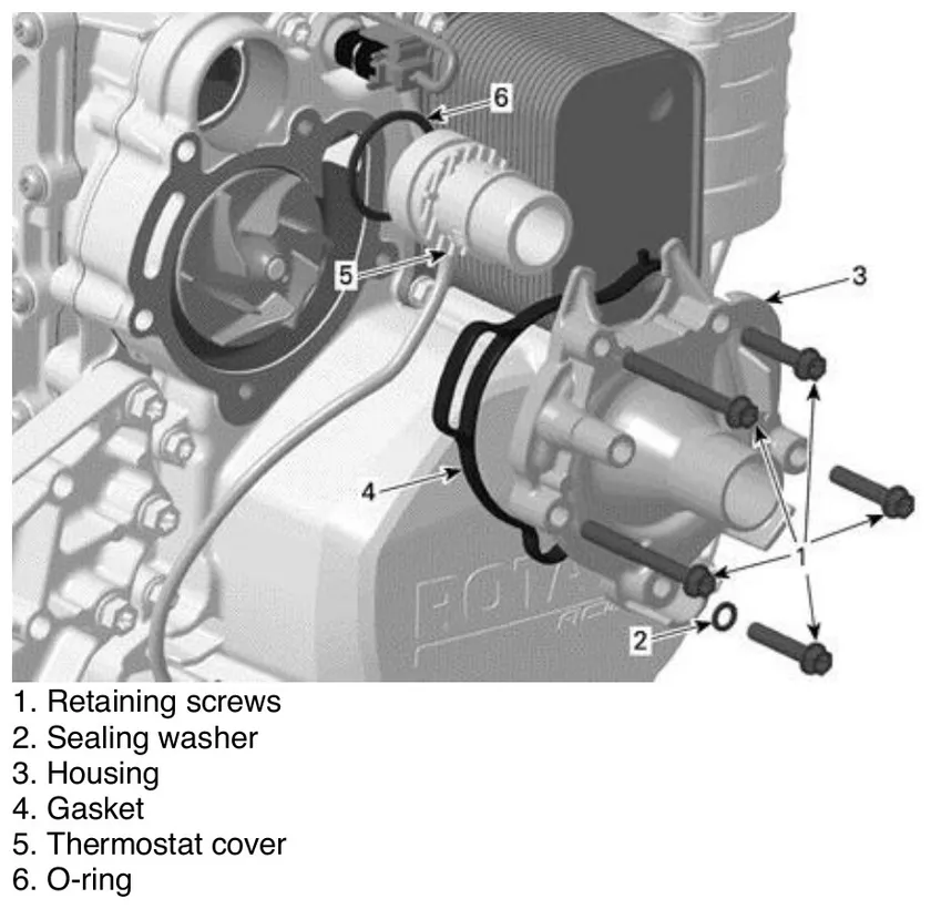
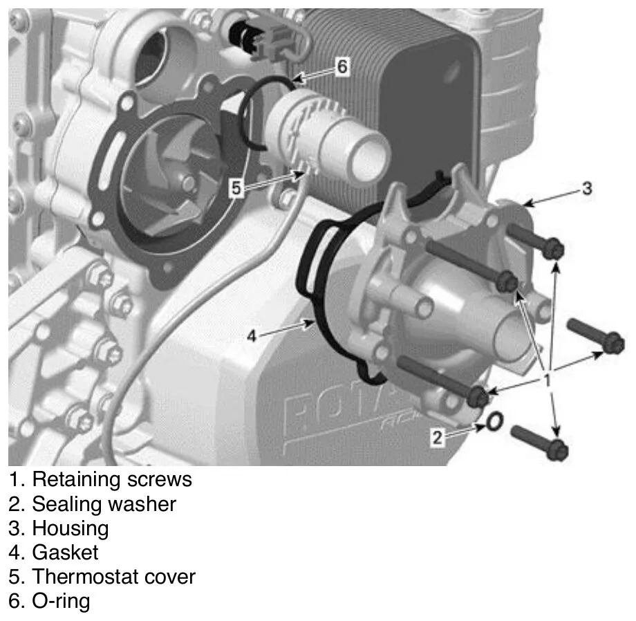
Remove water pump housing retaining screws.
- Step 12
Remove water pump housing with thermostat cover from magneto cover.
- Step 13
Remove oil cooler retaining screws, oil cooler and gasket. Discard gasket.

- Step 14
Pull oil pressure regulator parts from magneto cover by removing regulator plug and washer. Discard sealing washer.

- Step 15
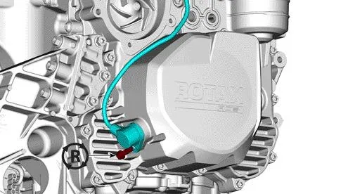
Remove CPS.
- Step 16
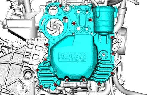
Remove magneto cover retaining screws.
- Step 17
Place an oil pan under magneto area to catch remaining oil.
- Step 18
Remove magneto cover.
Procedure
Removing the Stator
- Step 1
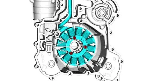
Remove and discard stator retaining screws.
- Step 2
Remove stator.
Procedure
Removing the Rotor
Perform the crankshaft locking procedure:
Note
When crankshaft is locked, the cylinder no. 2 is at TDC.
Caution
Crankshaft must be locked whenever the magneto rotor retaining nut has to be removed.
- Step 1
Remove ignition coils by removing the retaining screws.

- Step 2
Blow compressed air into spark plugs holes.
- Step 3
Remove spark plugs.
- Step 4
Remove the passenger seat.

- Step 5
Remove the battery.

- Step 6
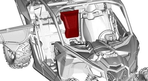
Remove Rear Service Cover.
- Step 7
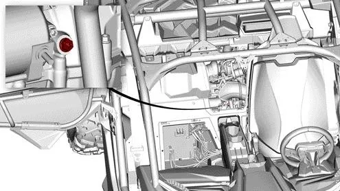
Remove and keep crankshaft access plug, discard gasket ring.
- Step 8
Rotate the crankshaft by rotating the magneto bolt clockwise until the locking position is reached.
NoteHaving someone to look through the crankshaft access hole to know when the locking hole is aligned with the access hole will greatly help.
- Step 9
Lock crankshaft using the crankshaft locking tool.
- Step 10
Remove rotor retaining screw and lock washer.

- Step 11
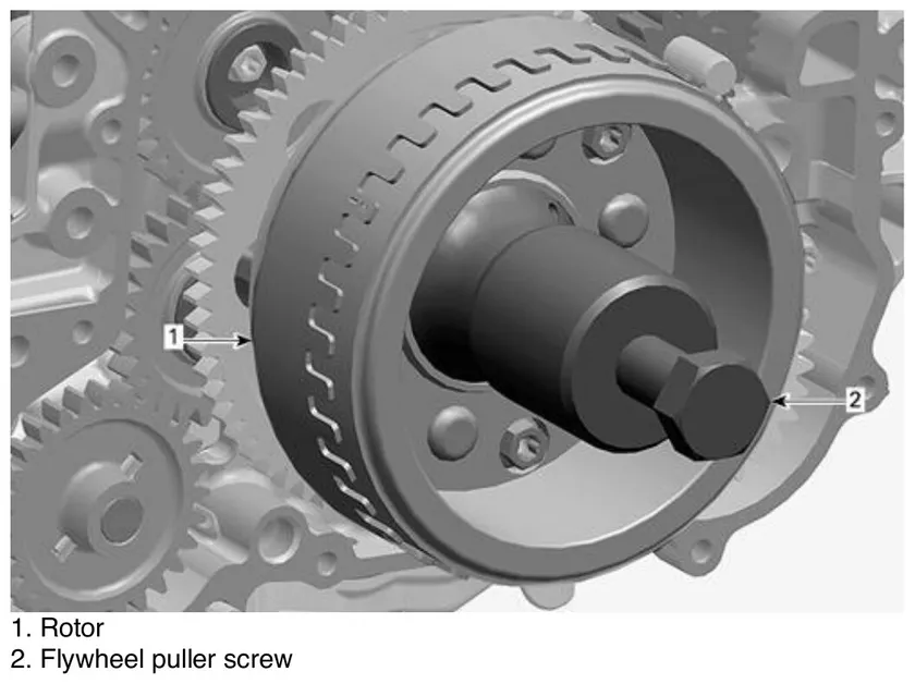
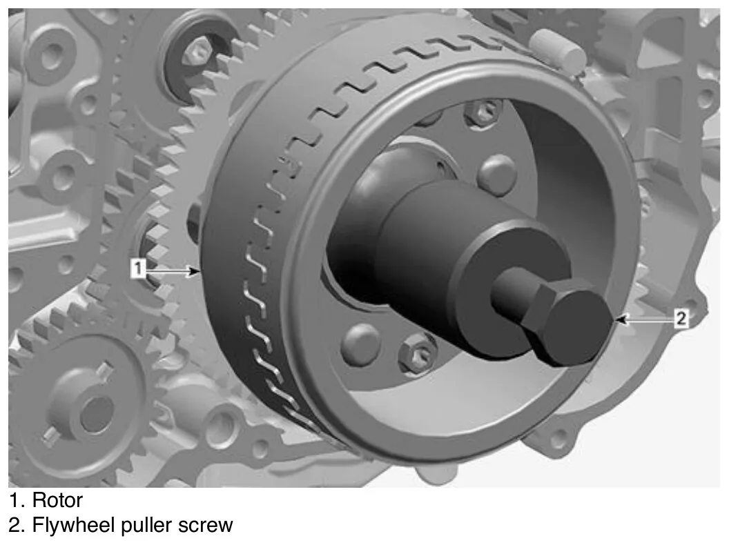
Install crankshaft protector and flywheel puller.
 Note
Apply some grease on the crankshaft protector surface to ease puller operation.
Procedure
Rotor and Stator
The installation of the rotor [P1] is the reverse of the removal procedure. However, pay attention to the following.
Blow the oil passage in the magneto hub using compressed air, ensure it is not clogged.
Using the recommended service product, clean:
- The oil passage
- The crankshaft thread
- The crankshaft taper
- The rotor taper.
service product
| CLUTCH AND PULLEY FLANGE CLEANER PRO S1 (P/N 779244) |
Caution
Taper on crankshaft and rotor must be free of grease.
Apply engine oil on sprag clutch and needle bearing.
Install sprag clutch gear onto rotor [P1].
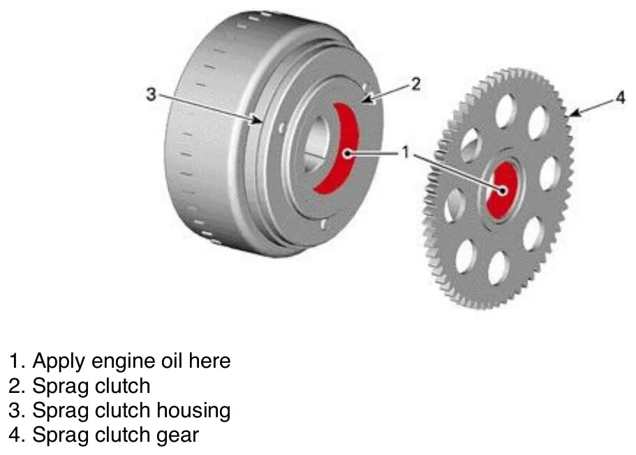
Slide rotor [P1] along with the sprag clutch gear onto crankshaft. The Woodruff key and keyway must be aligned.
Rotate sprag clutch gear counterclockwise to align with starter double gear.
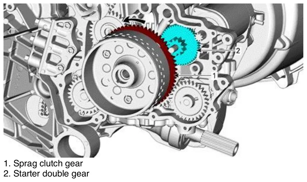
Remove all the old Loctite on the previously removed M16 x 35 retaining screw.
Apply Loctite on M16 x 35 screw.
Install washer and retaining screw. Tighten to specification.
tightening torque
| M16 x 35 screw | LOCTITE 243 (BLUE) (P/N 293 800 060) + 150 ± 10 N•m (111 ± 7 lbf•ft) |
Ensure that the stator plate [P2] cable is underneath the cable holder during installation of the stator.
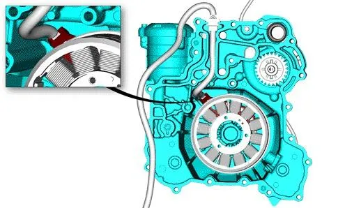
Install the stator plate [P2] using M6 x 30 socket head screw [P9]. Tighten to specification.
tightening torque
| M6 x 30 screw [P9] | LOCTITE 243 (BLUE) (P/N 293 800 060) + 9 ± 1 N•m (80 ± 9 lbf•in) |
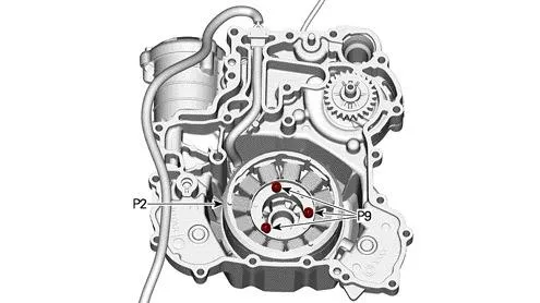
Clean magneto cover.
service product
| LOCTITE CHISEL (GASKET REMOVER) (P/N 413 708 500) |
Ensure starter drive gear pin in place.
Apply engine oil on the starter drive gear pin and on the water pump shaft.

Apply Loctite 5910 into the groove of the grommet and insert harness into the channel and the grommet into its seat in the ignition cover. Slightly pull harness towards outside while holding the grommet.
service product
| LOCTITE 5910 (P/N 293 800 081) |
Caution
Make sure that the stator cable harness is embedded into the channel. The part of the harness that is out of the channel must be tight, otherwise it might chafe or jam.
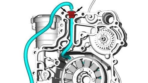
Apply Loctite 5910 onto the sealing surface of the grommet.
service product
| LOCTITE 5910 (P/N 293 800 081) |

Install a NEW magneto cover gasket [P6].
Carefully install magneto cover.
Warning
Magnetic force between magneto, flywheel and stator are very high. Avoid finger contusions.
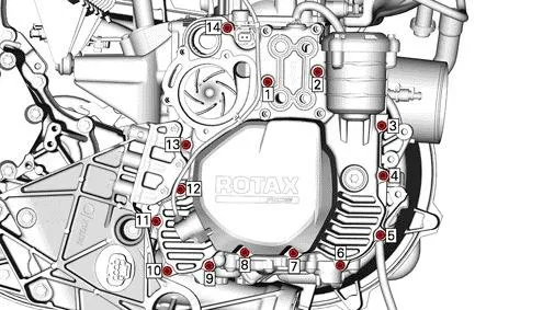
Tighten magneto cover screws according to the following sequence.
tightening torque
| Magneto cover retaining screw | 9 ± 1 N•m (80 ± 9 lbf•in) |
Reinstall the oil cooler with a new gasket [P8]. Tighten to specification in two steps by following the tightening sequence.
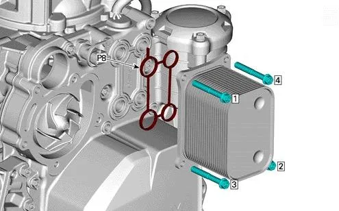
tightening torque
| Oil cooler retaining screw | Step 1 | 5 ± 0.6 N•m (44 ± 5 lbf•in) |
| Step 2 | 9 ± 1 N•m (80 ± 9 lbf•in) |
Reinstall the water pump housing with a new gasket [P7]. Tighten retaining screws to specification as per the following procedure.
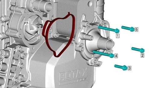
tightening torque
| Water pump housing retaining screw | 9 ± 1 N•m (80 ± 9 lbf•in) |
Unlock the crankshaft by removing the locking tool.
Install a new gasket ring on the plug screw.
Install the plug screw and tighten to specification.
tightening torque
| Plug screw | 10 ± 1 N•m (89 ± 9 lbf•in) |
Procedure
Voltage Regulator
Note
If a rear winch is installed, you will have to relocate the solenoid by following the original winch installation instructions.
Remove the 650W regulator.
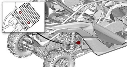
Following the template A, drill the holes for the new support [P5].
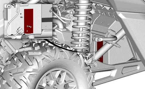
Install the support [P5] and 850W regulator [P3]. Secure using M6 elastic nut [P10].

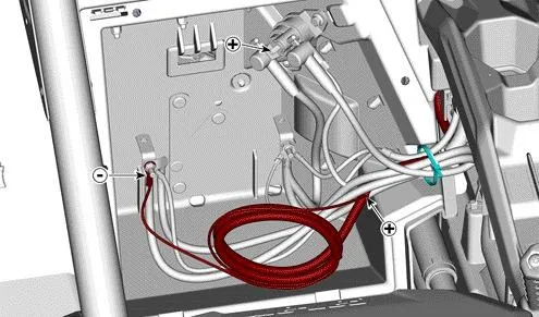
Remove the factory regulator positive wire (BK/YE) from the starter relay.
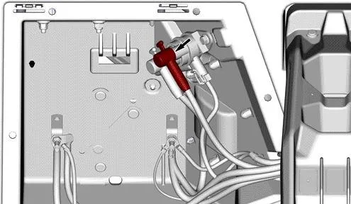
Note
Ensure to make a continuity test on the wire to ensure you removed the correct factory wire.
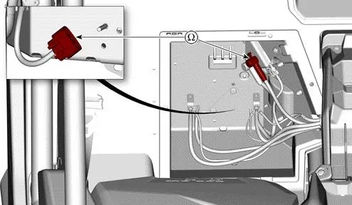
Connect the negative wire of the new regulator ([P3]) to the battery and the positive one on the starter relay.
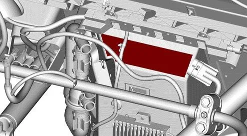
Position the template B and mark holes to drill.
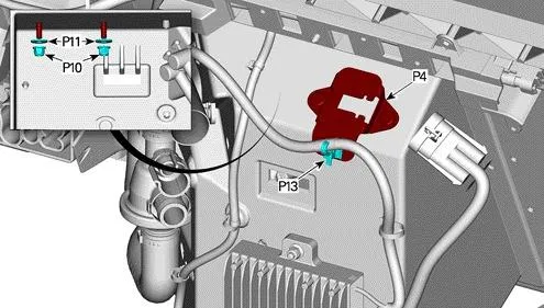
Install the new connector support [P4] and secure using flat washers [P11] and M6 elastic nut [P10].
Put dielectric grease on the connector of the old regulator and tape it.
Connect the regulator to the magneto.
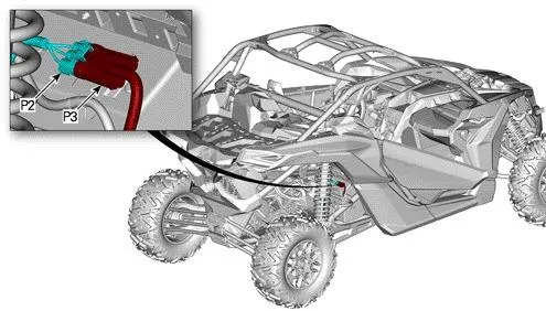
Reinstall all the removed parts.
Emissions notice. This product is exempt from the emission standards and related requirements of 40 C.F.R. § 1051 as provided by 40 C.F.R. § 1051.620, and California law [e.g., vehicle code §§ 27156 and 38391]. This product is sold only for use in connection with EPA certified, purpose-built, nonroad vehicles used solely for closed course, nonroad competition/racing and not used for any recreational purpose or on public highways or right of ways maintained by and open to the public. This product is sold only in connection with machines that do not fall under state and/or federal noise or emission standards/regulations. Purchasers who/that purchase this product represent and warrant that the product is purchased only in connection with EPA-certified, emission-regulations-exempt and noise-regulations-exempt competition/racing vehicles as interpreted under applicable state and/or federal law.
Need technical support?
Submit a ticket with your vehicle and what you're seeing, and our support team will get back to you.
