 BUY NOW, PAY LATER. Starting at 0% APR


Can-Am Maverick R Auxiliary Tank
Maverick R Auxiliary Tank
In the box
Parts and tools
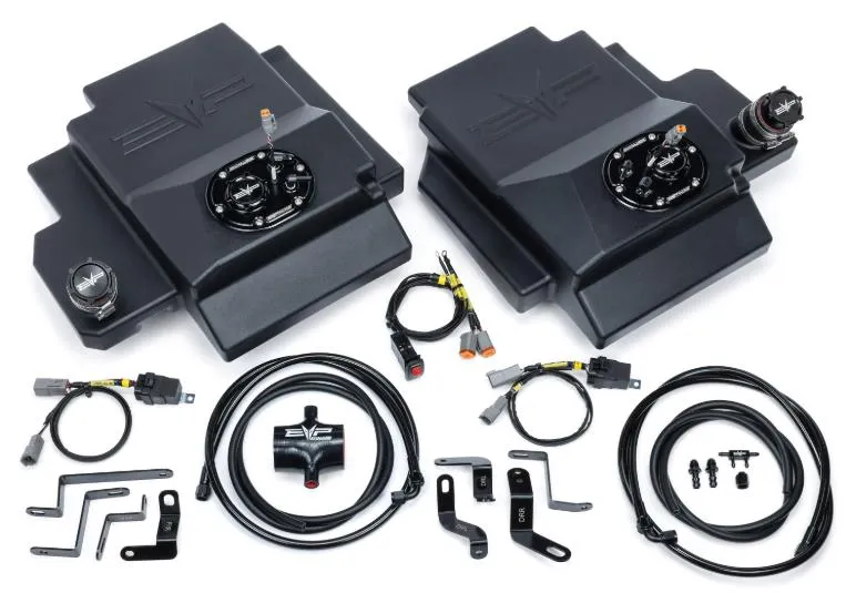
Included parts
- 1Passenger/Driver Side Tank
- 1Installation Kit, Passenger/Driver or Dual Kit
Required tools
- Screwdriver(s)
- Torx Socket Set
- Metric Socket Set
- Push Dart Tool
Procedure
Installation
- Step 1
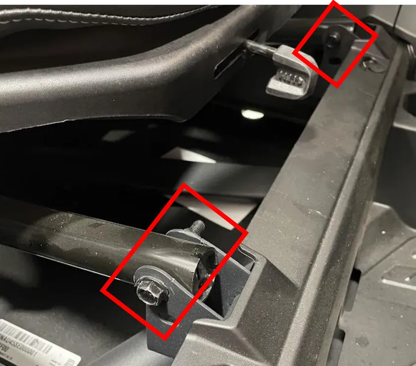
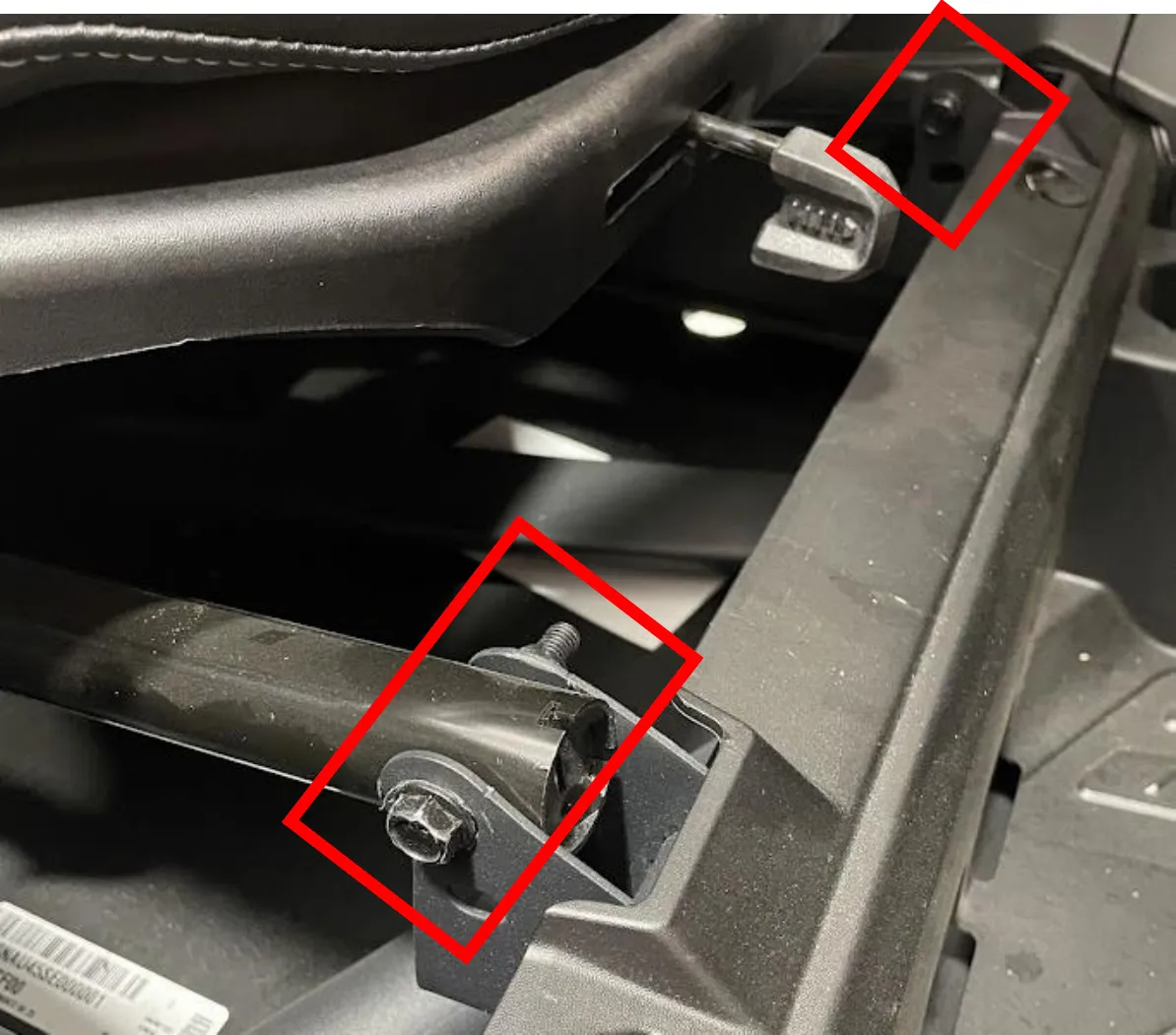
Remove the seat(s) front mounting bolts. Slide the seat all the way back. Remove (2) 13mm bolts with (2) 13mm locknuts.
- Step 2
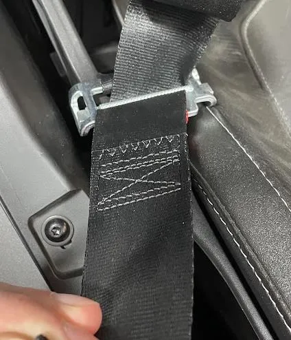
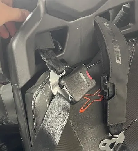
Unfasten the seat belt straps from the lower locks. Pull straps through the seat.
- Step 3
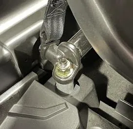
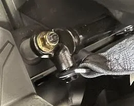
Slide the seat all the way forward, remove the rear seat locknuts and spacers (if on top). Use a 17mm socket.
- Step 4
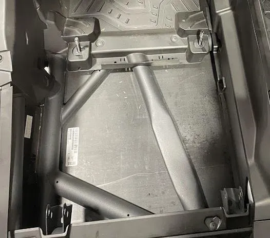
Slide the seat to the middle position before removing it from vehicle.
- Step 5
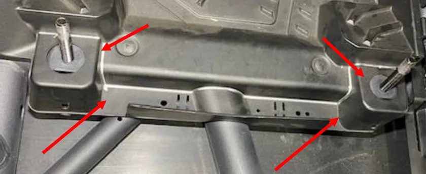
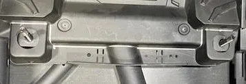
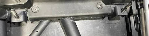
MAX ONLY: With a Dremel, jig saw, carbide bit- cut the plastic on the silver line. 2-door vehicles this is NOT NEEDED.
- Step 6
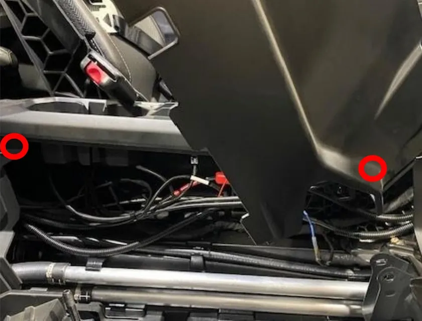
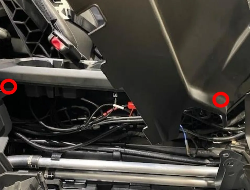
Remove the side tunnel plastic. Remove (2) T-30 on the rear (it may help to remove the cup holder), pop the panel out of 3 clips, twist upward and remove (2) gold T-30 located on the very front of the panel, inside the tunnel.
- Step 7
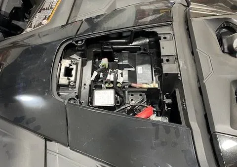
Remove the front fuse box cover.
- Step 8
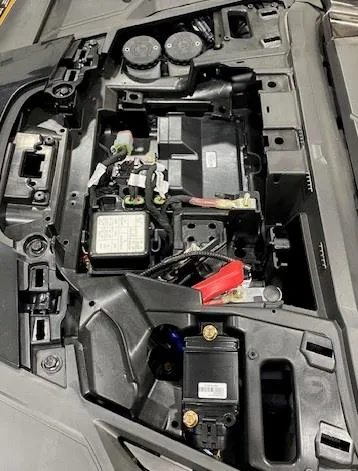
Remove both driver and passenger side trim panels, pop out of (4) clips.
- Step 9
Remove the upper glove box lid, open fully and pull upward.
- Step 10
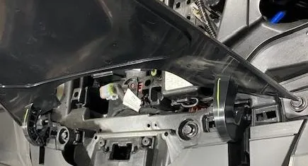
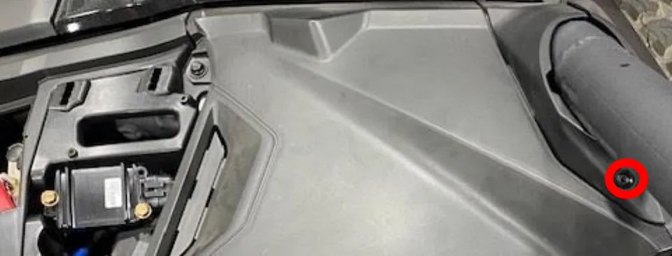
Remove both passenger and driver side dash to cage trim. Remove (1) T-25.
- Step 11
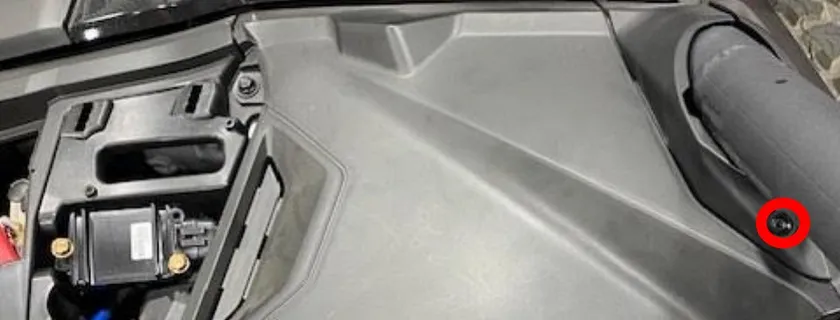
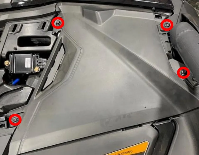
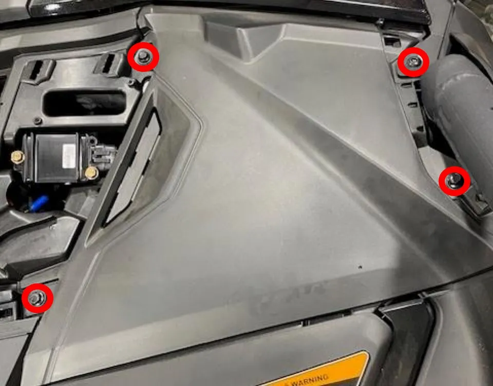
Remove both passenger and driver side upper dash panels. (3) 10mm screws and (1) T-30 screw.
- Step 12
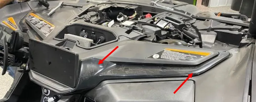
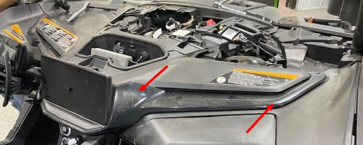
Remove both passenger and driver side dash trim pieces. Pull out of (4) clips.
- Step 13
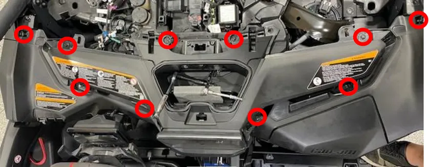
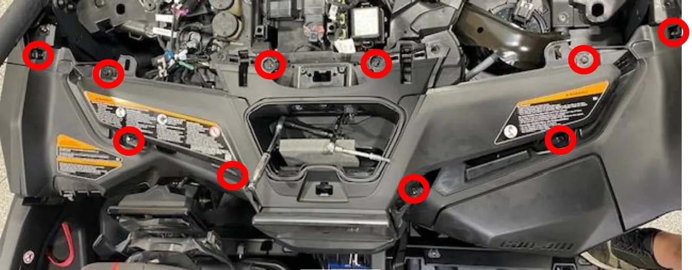
Remove the central dashboard kit, remove (8) 10mm screws and washers.
- Step 14
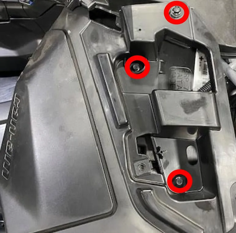
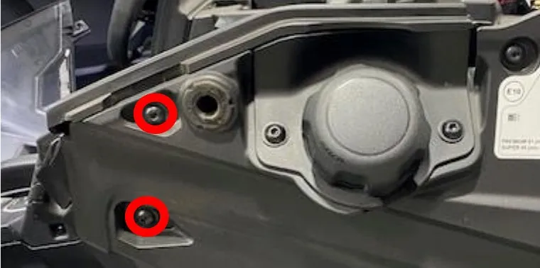
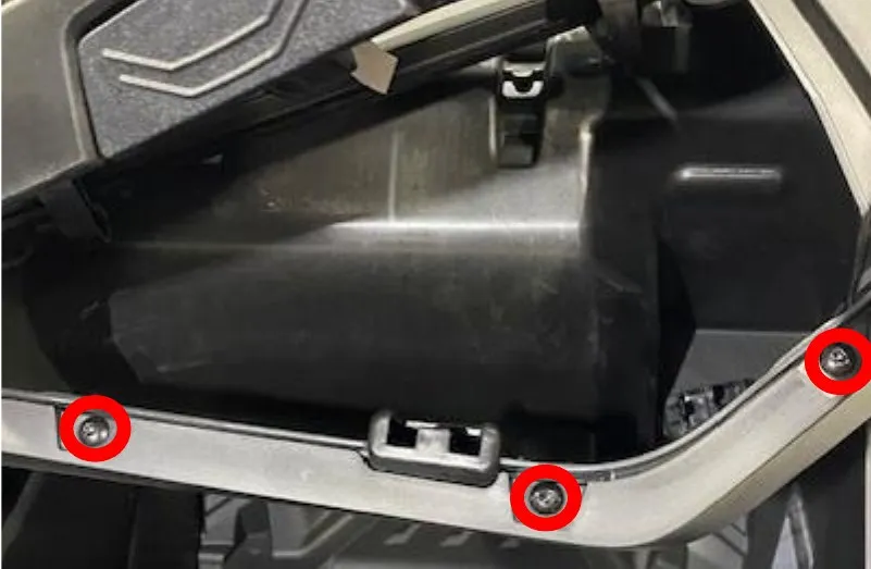
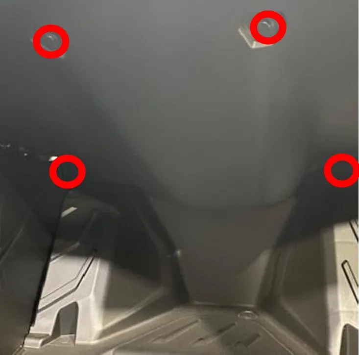
Remove the passenger glove box, (3) 10mm screws on top, (3) T-25 screws inside the glove box, (2) T-30 screws behind the gas door, (4) push darts underneath the glove box holding the interior trim on.
- Step 15
Remove the glovebox, you can keep the glove box lower trim piece in or remove it.
- Step 16
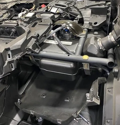
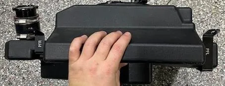
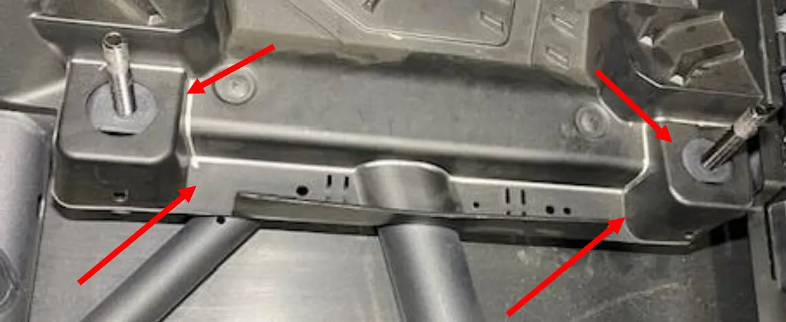
Passenger Side: Install the brackets to the tank loosely, use supplied M8-1.50 x 12mm hardware. The brackets are labeled as PFL = passenger front left, PFR = passenger front right, PRL = passenger rear left, PRR = passenger rear right. Install the tank with brackets into the vehicle to get an idea of where the brackets need to be. Once completed, remove each bracket fastener, apply BLUE Loctite to the threads and torque hardware down for the final time.
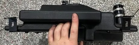
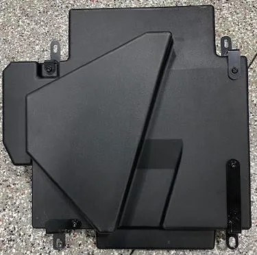
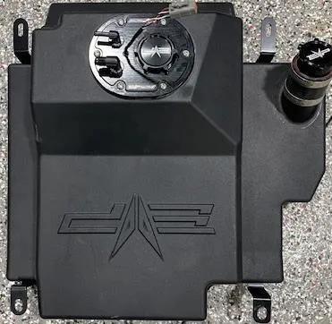
- Step 17
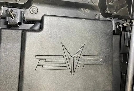
Install the tank into the vehicle.
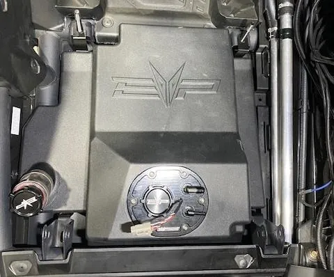
- Step 18
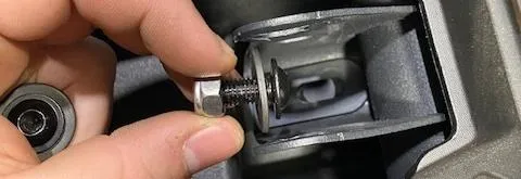
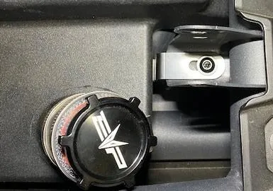
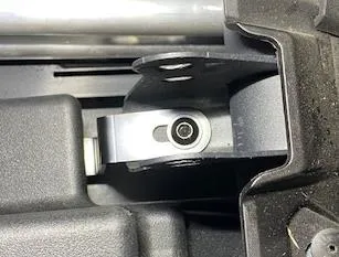
Install the supplied M8 x 16mm bolt with washer and locknut on the bottom of the front mounts. Use an 5mm Allen and 13mm short wrench to fasten down.
- Step 19
Driver Side: Install the brackets to the tank loosely, use supplied M8-1.50 x 12mm hardware. The brackets are labeled as DFL = driver front left, DFR = driver front right, DRL = driver rear left, DRR = driver rear right. Install the tank with brackets into the vehicle to get an idea of where the brackets need to be. Once completed, remove each bracket fastener, apply BLUE Loctite to the threads and torque hardware down for the final time.
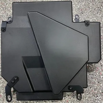
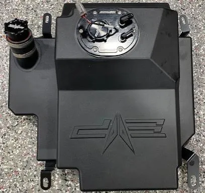
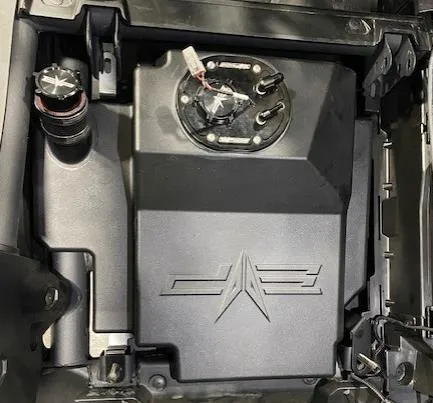
- Step 20
Locate the PTFE fuel hose, passenger side is 54”, driver side 60”.
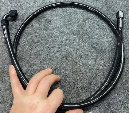
- Step 21
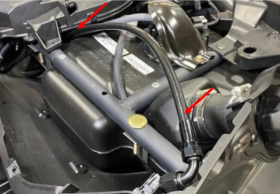
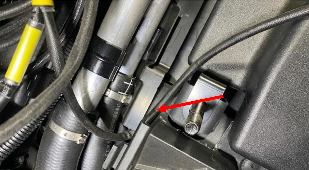
Passenger Side: Route the straight end from the gas tank, down into the center tunnel (on passenger side) up to the auxiliary tank as shown.
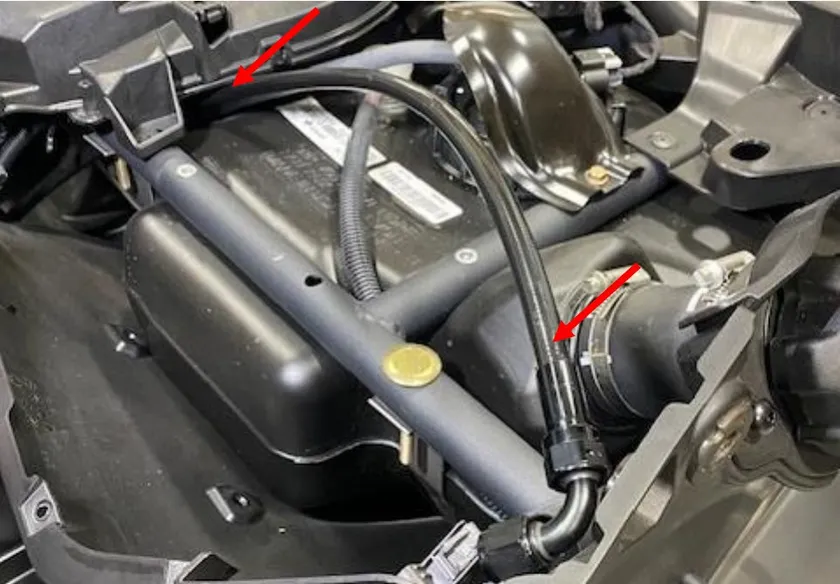
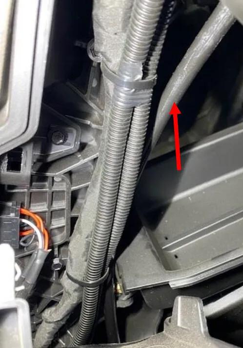
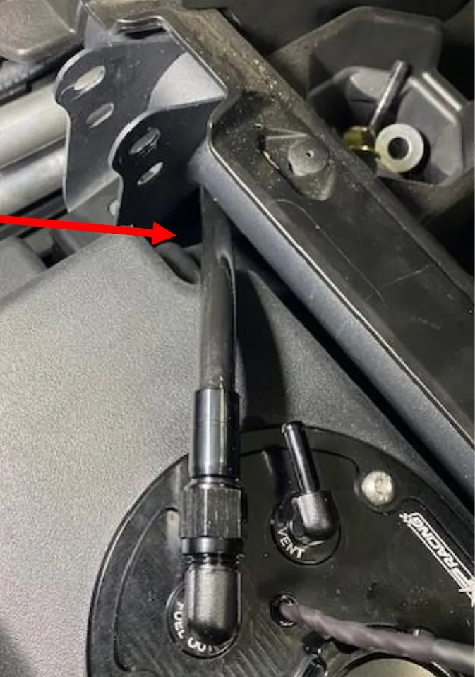
Make sure the hose will not interfere with the seat rails. Keep the hose in front of the bracket. - Step 22
Locate the 1/4" 54 or 60” vent hose, route that hose the same way. Install 13.3 pinch.
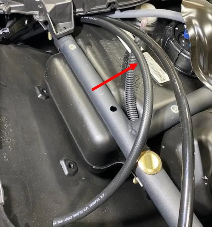
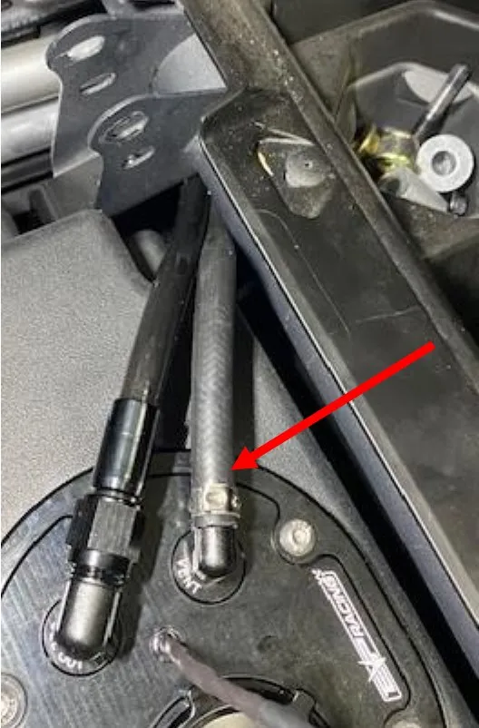
Cut the hose to length if needed. Make sure the hose isn’t kinked and has space. - Step 23
Driver Side: Route the straight end from the gas tank, down into the center tunnel (follow the OEM fuel hose on drivers side) up to the auxiliary tank as shown.
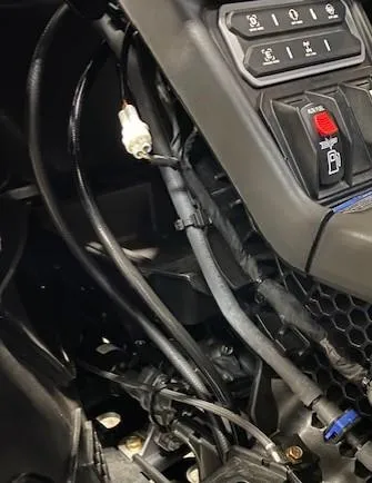
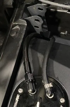
- Step 24
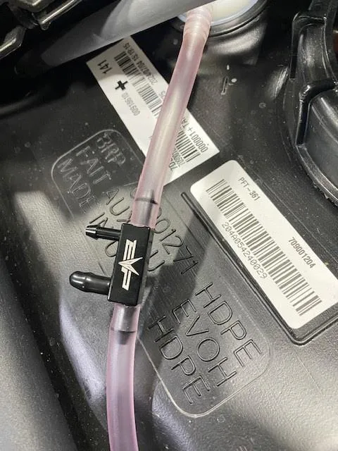
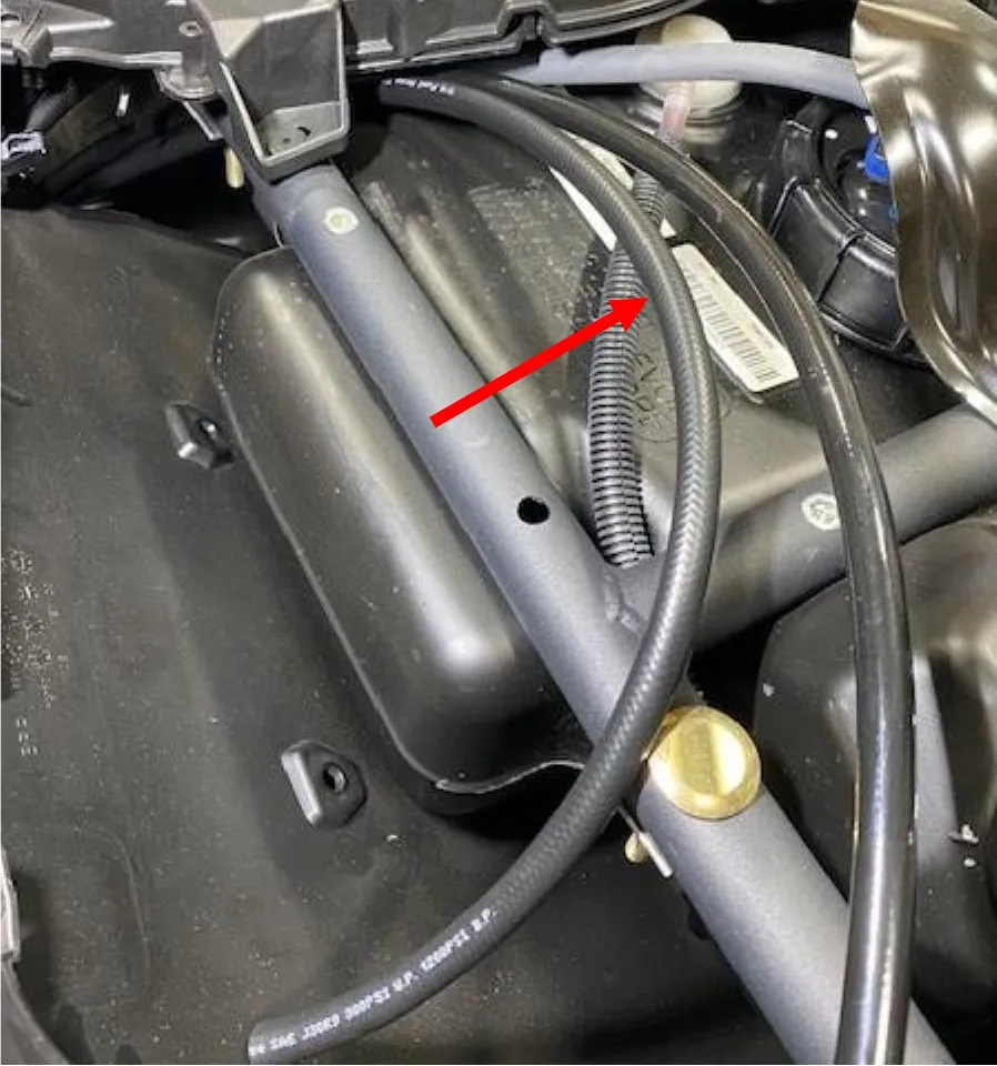
Locate the vent line off the OEM tank, peel back 5-6” of sleeving and cut it off. Locate the EVP vent block. Install the vent block in-line with the OEM PINK vent hose.
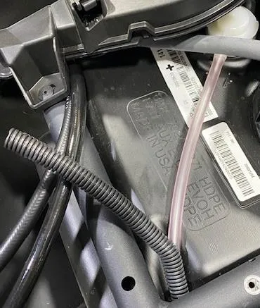
 Note
If you are running dual tanks you will use both barbs, if you are running one tank, cap the port not being used.
- Step 25
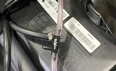
Connect the 1/4" rubber hose to the vent block, use supplied 13.8mm pinch clamp.
- Step 26
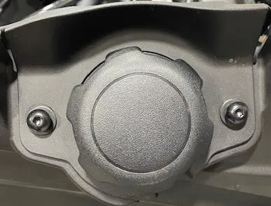
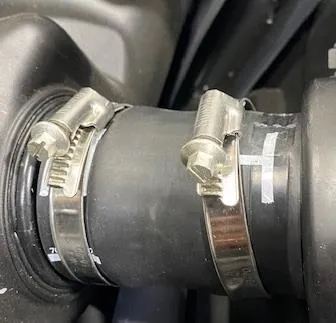
Remove the (2) T-30 screws holding the filler neck trim plate on. Loosen both filler neck worm drive clamps.
- Step 27
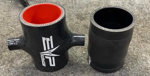
Remove the OEM filler neck, locate the EVP filler neck.
- Step 28
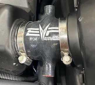
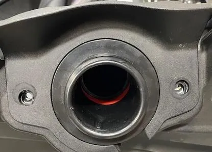
Install the new filler neck onto the OEM tank, re-use OEM hardware.
- Step 29
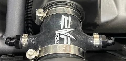
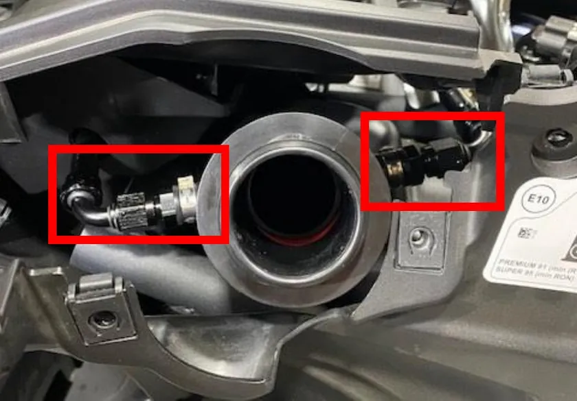
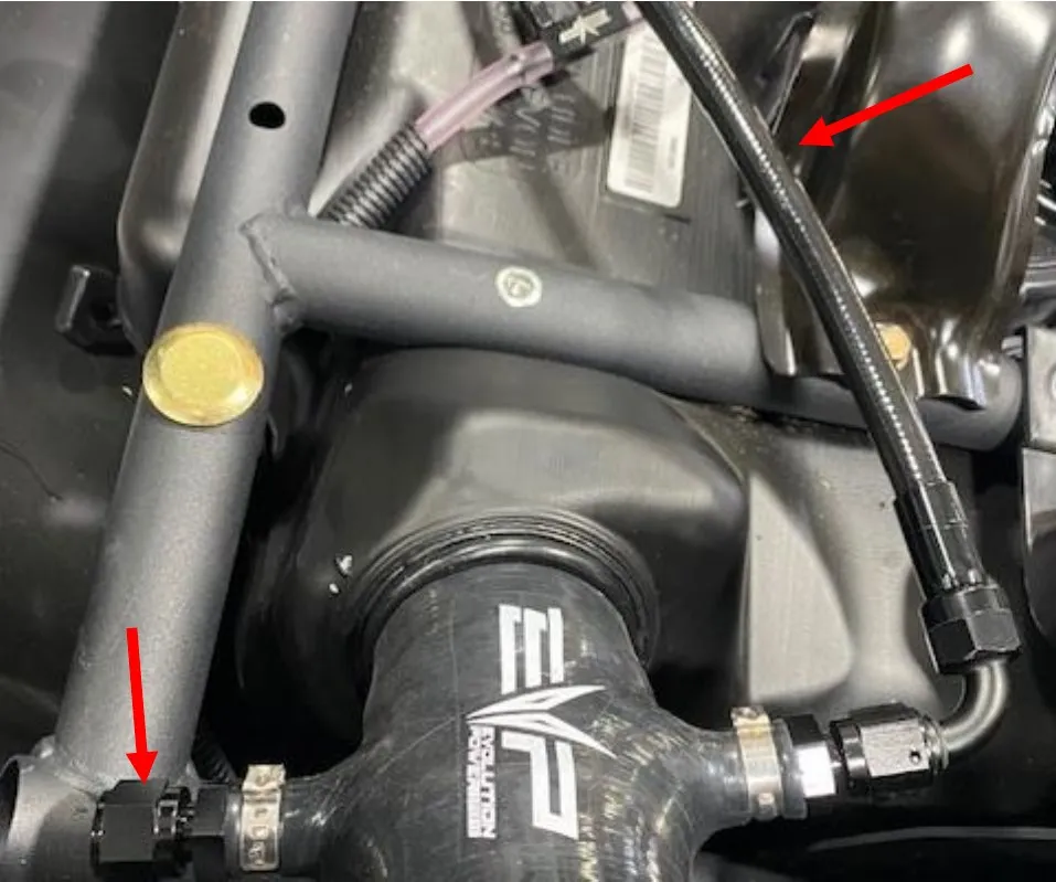
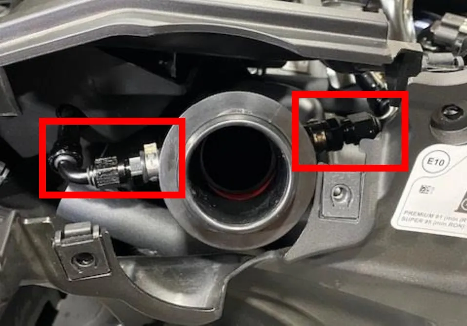
Install the supplied 6AN barb fittings into filler neck, fasten with 19.2mm pinch clamps.
- Step 30
If you run one tank, run the fuel fill hose to the right port. Cap the left port with a 6AN cap. With the left over 1/4" vent hose, cut 2.0” off and place over the fuel pump bracket in case the hose rubs, or use zip ties to hold the hose away from the bracket.
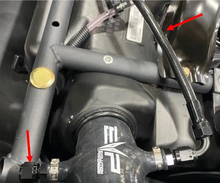
- Step 31
If you are already running one side and installing the other side, locate the passenger glove box and find the location to drill a hole. 22.0mm over and 27mm upward, see silver dot.
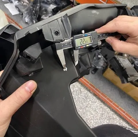
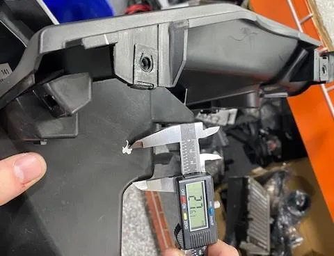
- Step 32
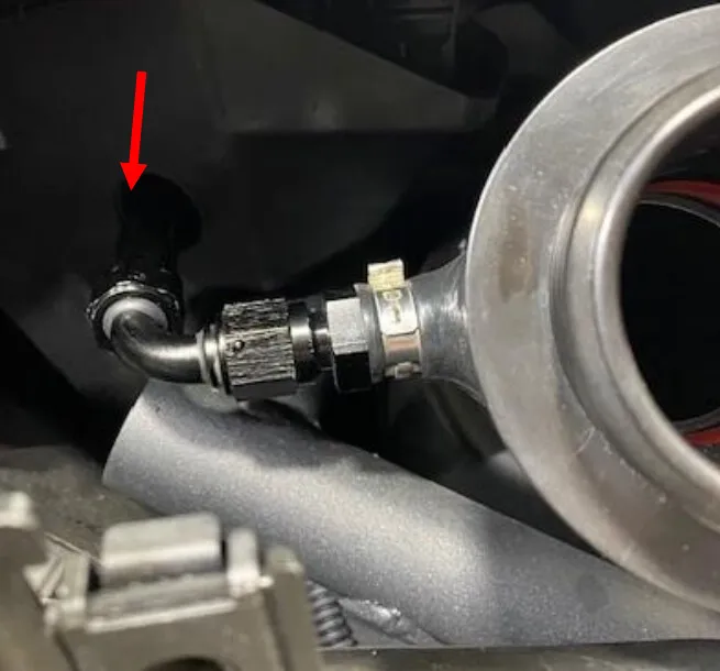
With a step bit, drill a hole 20-24mm in diameter, or large enough to fit the 90-degree fitting through.
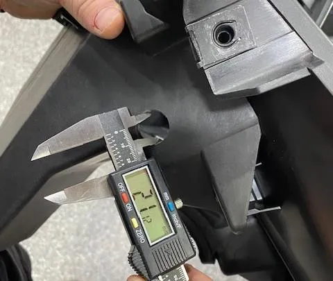
- Step 33
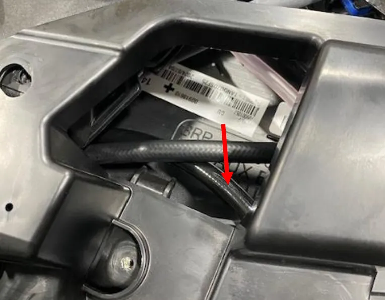
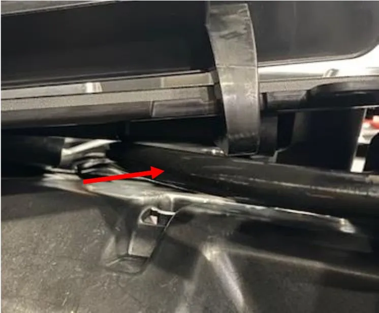
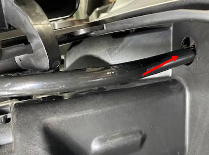
With the glovebox loosely in place, route the other fuel feed hose as follows.
- Step 34
If running both tanks, this is how the filler neck will look. Tighten both 6AN fittings.
- Step 35
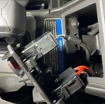
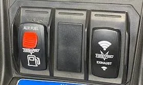
Locate a blank rocker switch location, install the supplied lock out switch and plug the harness into the switch.
- Step 36
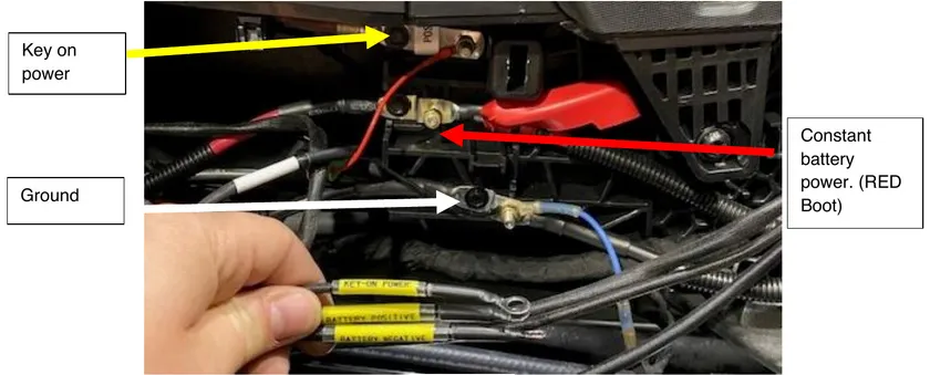
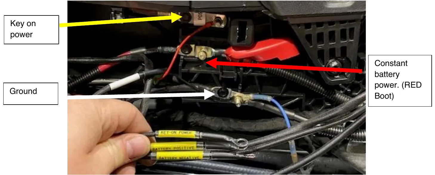
Locate the bus bar in the center tunnel, connect the switch harness.
- Step 37
Install the fuel pump relay harness to the switch harness. If you are only running one tank, install the supplied blank plug on the other switch harness plug.
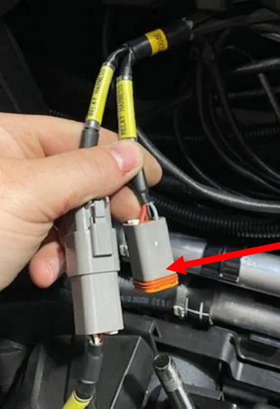
Cap this plug if running one tank. If running dual, you will use both plugs. - Step 38
Zip tie the switch and relay harness into the center tunnel.
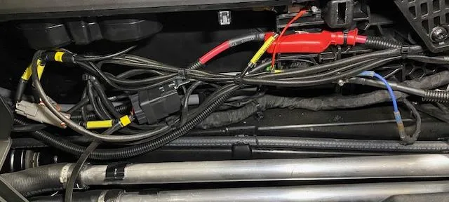
- Step 39
Route the relay harness as shown to the auxiliary fuel tank.
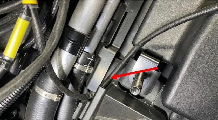
- Step 40
Install the supplied zip tie mount to the tank and zip tie the harness. Plug the fuel hat connector into the relay pigtail.
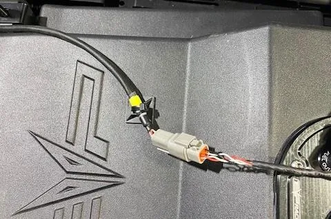
- Step 41
Fill the auxiliary tank with the correct fuel for your tune, key the vehicle on and turn the auxiliary tank on. Look for any leaks, make sure everything is tight. Once completed, reinstall all factory parts in reverse order.
When you’re done
After installation
The auxiliary tank will shut off once it is out of fuel. The auxiliary tank does NOT know when the OEM tank is full, keep an eye on the fuel gauge located on the gauge cluster.
Need technical support?
Submit a ticket with your vehicle and what you're seeing, and our support team will get back to you.
