 BUY NOW, PAY LATER. Starting at 0% APR


ENGINE DISASSEMBLY / INSPECTION - TOP END
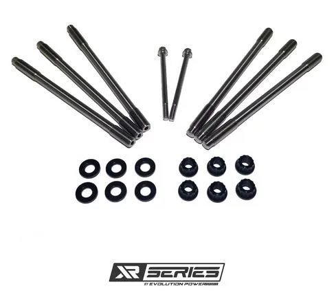
Polaris XR Series XP Turbo/S & Pro XP 11mm CA625 Head Stud Kit
XR Series XP Turbo/S & Pro XP 11mm CA625 Head Stud Kit
Before you start
Caution
THIS JOB REQUIRES MECHANICAL SKILL. IF YOU DO NOT HAVE THE MECHANICAL SKILL, LEAVE THIS JOB TO A PROFESSIONAL! SEVERE ENGINE DAMAGE WILL OCCUR IF YOU DO NOT KNOW PROPER MECHANICAL PROCEDURES! THESE INSTRUCTIONS ARE FOR REFERENCE ONLY. REFER TO THE POLARIS SHOP MANUAL FOR FURTHER INSTRUCTIONS!
In the box
Parts and tools
Included parts
- 611mm Nuts
- 611mm Washers
- 611mm Studs
- 1Assembly Lube
- 26mm Head Studs
Required tools
- Torque Wrench (ft-lb)
- Metric Socket Set
- Flat Head Screwdriver
- Torx Set
Procedure
Installation
- Step 1
Although this job can be done without removing the bed, it is far easier with it removed.
- Step 2
Remove heat shields to provide clear access to the top of the engine.
Procedure
Valve Cover Removal
Note
The valve cover can be removed with the engine installed in the chassis.
- Step 1
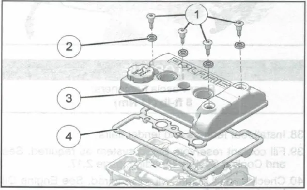
Remove the four valve cover shoulder bolts ① and isolators ② using a T40 driver.
 Caution
Replace rubber isolators upon assembly.
- Step 2
Remove valve cover ③ and valve cover seal ④. Replace isolators and valve cover seal if oil leaks are evident.
- Step 3
If tearing down the top end of the engine, remove the spark plugs. Stuff spark plug holes with clean shop towels to prevent any debris from falling into the combustion chamber.
Procedure
Camshaft Removal
Note
The camshafts can be removed with the engine installed in the chassis.
- Step 1
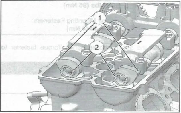
Rotate the engine so the PTO cylinder is at Top Dead Center (TDC) to relieve most of the valve spring pressure. The camshaft lobes ① should face out and the slots on the end of the camshafts ② should line up.
- Step 2
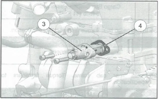
Remove the fasteners retaining the cam chain tensioner ③ to the cylinder. Use a new tensioner gasket ④ upon assembly.
- Step 3
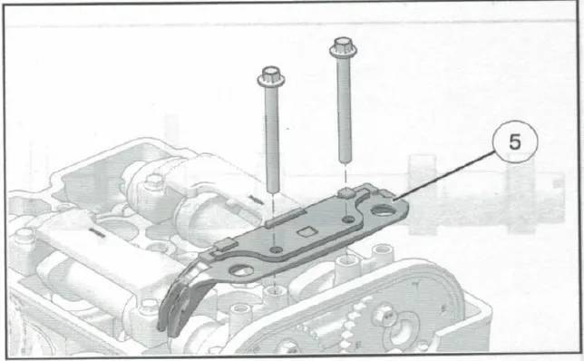
Remove the two bolts retaining the fixed cam chain guide ⑤ and remove the assembly from the engine.
- Step 4
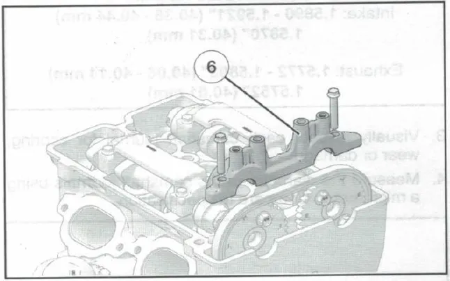
Remove the remaining two bolts that retain the front camshaft carrier ⑥ and carefully lift the carrier off the camshafts.
- Step 5
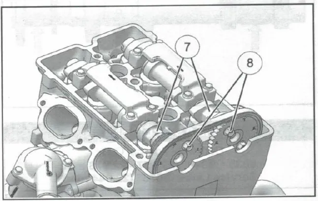
Hold camshafts ⑦ with an open-end wrench, and remove the top bolt ⑧ from each camshaft sprocket.
- Step 6
Rotate the engine to allow access to the remaining bolt on each camshaft sprocket.
- Step 7
Remove the remaining bolt from each camshaft sprocket.
- Step 8
Lift the chain and sprockets off the camshafts to allow each sprocket to be removed.
- Step 9
Using a paperclip or other tool, hold cam chain up.
NoteThe crankcase has a built-in lower guide to prevent the chain from falling off the crankshaft.
- Step 10
Evenly loosen the four bolts retaining each rear camshaft carrier ⑨ and carefully lift the carriers off the camshafts.

- Step 11
Mark the intake ⑩ and exhaust ⑪ camshafts to ensure proper assembly.
- Step 12
Carefully remove camshafts from the cylinder head.
Procedure
Installation
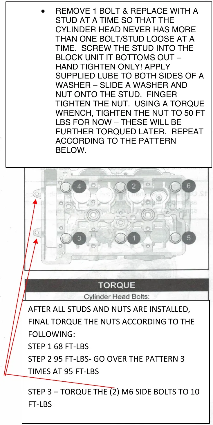
- REMOVE 1 BOLT & REPLACE WITH A STUD AT A TIME SO THAT THE CYLINDER HEAD NEVER HAS MORE THAN ONE BOLT/STUD LOOSE AT A TIME. SCREW THE STUD INTO THE BLOCK UNIT IT BOTTOMS OUT – HAND TIGHTEN ONLY! APPLY SUPPLIED LUBE TO BOTH SIDES OF A WASHER – SLIDE A WASHER AND NUT ONTO THE STUD. FINGER TIGHTEN THE NUT. USING A TORQUE WRENCH, TIGHTEN THE NUT TO 50 FT LBS FOR NOW – THESE WILL BE FURTHER TORQUED LATER. REPEAT ACCORDING TO THE PATTERN BELOW.
TORQUE
Cylinder Head Bolts:
AFTER ALL STUDS AND NUTS ARE INSTALLED, FINAL TORQUE THE NUTS ACCORDING TO THE FOLLOWING:
| STEP 1 | 68 FT-LBS |
| STEP 2 | 95 FT-LBS- GO OVER THE PATTERN 3 TIMES AT 95 FT-LBS |
| STEP 3 | TORQUE THE (2) M6 SIDE BOLTS TO 10 FT-LBS |
Procedure
Camshaft Installation / Timing
Note
If any valve train components were replaced, refer to Valve Clearance Adjustment, page 2.12 procedure prior to performing this procedure.
- Step 1
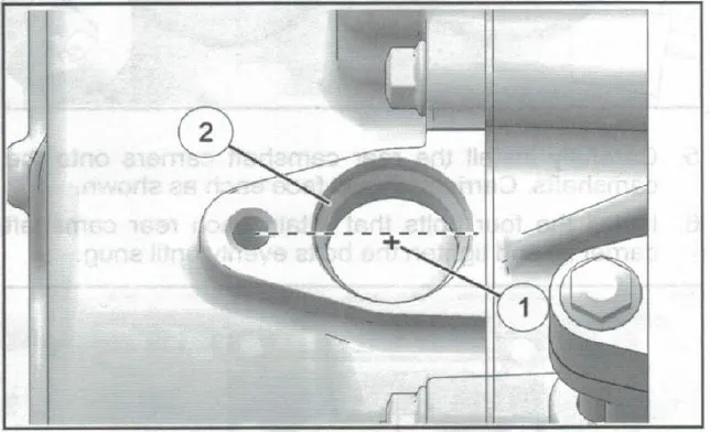
Rotate the engine until the flywheel Top Dead Center (TDC) mark ① is aligned or centered in the Crankshaft Position Sensor (CPS) mounting hole ②. This places the PTO cylinder at TDC for camshaft installation.
 Caution
DO NOT use the “V” mark located on the flywheel. Only the “+” mark should be used as a TDC reference.
- Step 2
Reference the intake and exhaust markings made during disassembly. If installing new camshafts or if camshafts were not marked, you can reference the part number stamped on the end of the shafts.
| Intake Camshaft - 3023053 |
| Exhaust Camshaft - 3023052 |
- Step 3
Lubricate all camshaft lobes and bearing journal surfaces with Polaris PS-4 engine oil prior to installation.
- Step 4
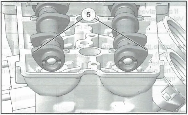
Carefully install the camshafts into the cylinder head. The PTO camshaft lobes ⑤ should face out.
- Step 5
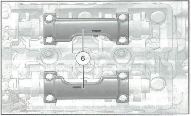
Carefully install the rear camshaft carriers onto the camshafts. Carriers should face each as shown.
- Step 6
Install the four bolts that retain each rear camshaft carrier ⑥ and tighten the bolts evenly until snug.
- Step 7
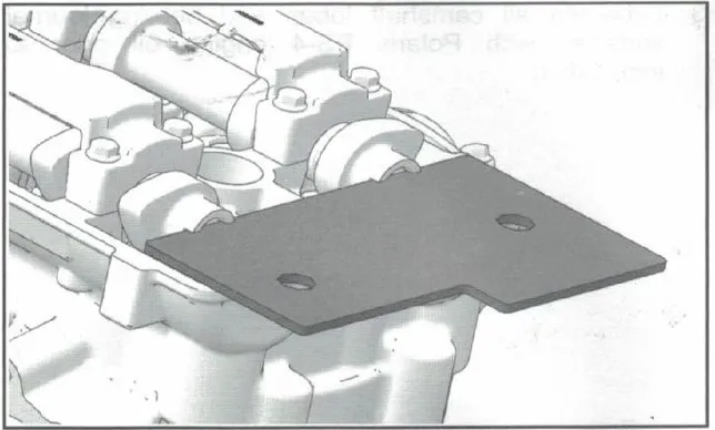
Install the Cylinder Holding & Camshaft Timing Plate (PU-50563) into the end of camshafts as shown. Use an open-end wrench to rotate camshafts slightly.
- Step 8
Verify TDC mark on the flywheel is still properly aligned (see Step 1).
- Step 9
Pull cam chain upward, making sure it is engaged with the drive sprocket on the crankshaft.
- Step 10
While lifting the cam chain up, engage the cam sprockets into the chain with the “I” and “E” marks facing out.
- Step 11
Install the sprockets onto the camshafts and align the sprocket marks with the valve cover gasket surface (refer to Camshaft Timing Quick Reference, page 3.89).
NoteIntake cam sprocket should have “I” marks aligned close to gasket surface and the exhaust cam sprocket should have “E” marks aligned. Install the exhaust cam sprocket first to ensure proper cam timing.
- Step 12
camshaft sprocket retaining bolts upon assembly. bolt ⑧ in each camshaft sprocket ⑦. Do not torque the bolts at this time.
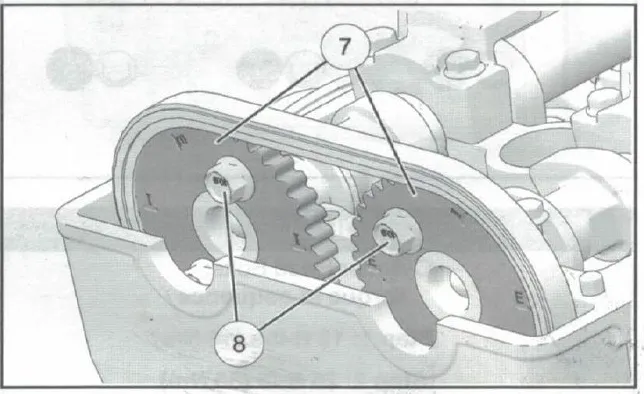
Apply blue Locktite and install NoteUse new sprocket retaining bolts upon assembly.
- Step 13
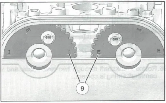
Verify cam timing is correct. Flywheel TDC mark should still be aligned (see Step 1) and cam sprocket markings should line up as shown.
NoteThe I and E marks may not be exactly parallel with the top of the cylinder head.
Timing View for Sprockets
For correct sprocket orientation, ensure the “I” for intake and the “E” for exhaust are positioned as shown ⑨. View from mag side.
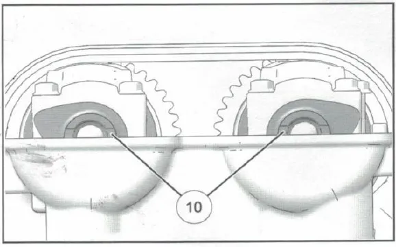
Timing View for Camshafts
Align slot of both cams with the top deck of the head ⑩. Position 4mm thick flat bar through slots to lock cams in correct position.
- Step 14
If timing marks are not aligned, remove sprockets and correct alignment.
- Step 15
Remove the Cylinder Holding & Camshaft Timing Plate (PU-50563) from the end of the camshafts.
- Step 16
Apply Polaris PS-4 engine oil to the cam chain tensioner bore prior to assembly.
- Step 17
Rotate the engine using the flywheel and install the remaining bolt in each camshaft sprocket. Hold camshafts in place with an open-end wrench and torque the sprocket bolts to specification.
TORQUE
Camshaft Sprocket Bolts: 14 ft-lb (19 Nm)
- Step 18
Rotate the engine using the flywheel and torque the remaining sprocket bolts to specification.
- Step 19
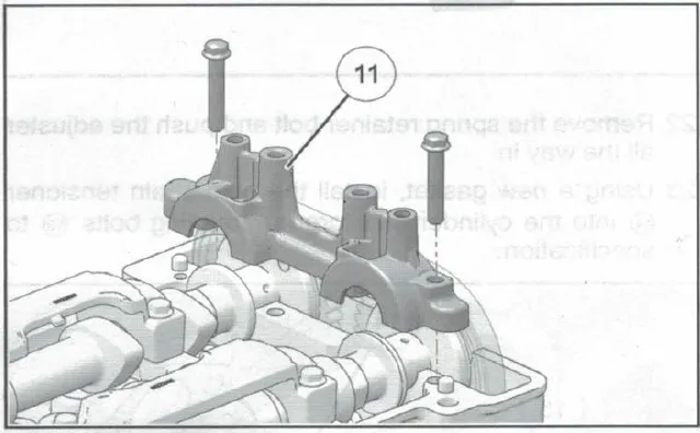
Install the front camshaft carrier ⑪ and two outer retaining bolts.
- Step 20
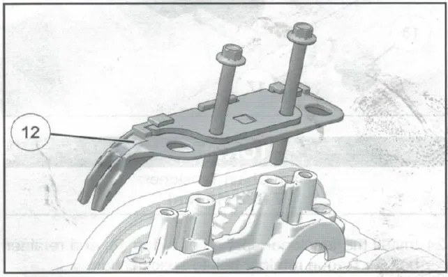
Install the fixed cam chain guide ⑫ and two retaining bolts.
- Step 21
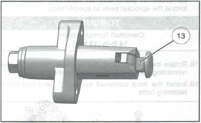
Lubricate the rack ⑬ on the tensioner with white lithium grease.
- Step 22
Remove the spring retainer bolt and push the adjuster all the way in.
- Step 23
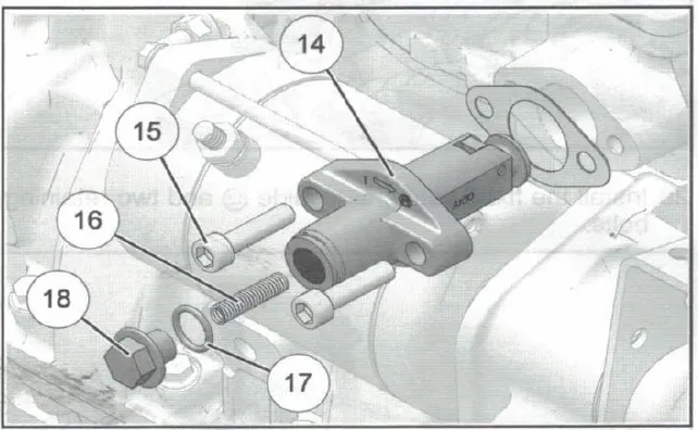
Using a new gasket, install the cam chain tensioner ⑭ into the cylinder and torque mounting bolts ⑮ to specification.
TORQUE
Cam Chain Tensioner: 7 ft-lb (10 Nm)
- Step 24
Install the tensioner spring ⑯, o-ring ⑰, and retainer bolt ⑱. Torque retainer bolt to specification.
NoteThe tensioner will automatically adjust to the proper tension once the spring and retainer are installed. No further adjustment is required.
TORQUE
Tensioner Spring Retainer: 12 ft-lb (16 Nm)
- Step 25
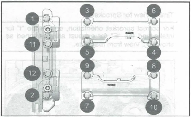
Torque the camshaft carriers bolts in sequence to specification.
TORQUE
Camshaft Carrier Bolts: 7 ft-lb (10 Nm)
- Step 26
Rotate crankshaft through two revolutions and verify camshaft timing is correct.
Reinstall valve cover and torque bolts to 7 ft-lbs.
Reinstall spark plugs and torque to 10 ft-lbs.
Reinstall heat shields and all other parts removed for the install.
Emissions notice. This product is exempt from the emission standards and related requirements of 40 C.F.R. § 1051 as provided by 40 C.F.R. § 1051.620, and California law [e.g., vehicle code §§ 27156 and 38391]. This product is sold only for use in connection with EPA certified, purpose-built, nonroad vehicles used solely for closed course, nonroad competition/racing and not used for any recreational purpose or on public highways or right of ways maintained by and open to the public. This product is sold only in connection with machines that do not fall under state and/or federal noise or emission standards/regulations. Purchasers who/that purchase this product represent and warrant that the product is purchased only in connection with EPA-certified, emission-regulations-exempt and noise-regulations-exempt competition/racing vehicles as interpreted under applicable state and/or federal law.
Need technical support?
Submit a ticket with your vehicle and what you're seeing, and our support team will get back to you.
