 BUY NOW, PAY LATER. Starting at 0% APR


Polaris Pro R & Turbo R Auxiliary Fuel Tank Kit
Installation instructions for the Pro R & Turbo R Auxiliary Fuel Tank Kit on the Polaris Pro R (RZR) (SKU 500RP0062). Parts, tools, and full procedure.
In the box
Parts and tools
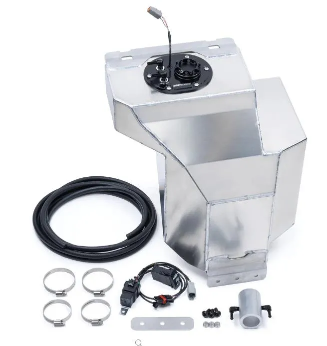
Included parts
- 1Pro R Auxiliary Fuel Tank Assembly
- 1Auxiliary Tank Filler Adaptor Kit
- 1Auxiliary Tank Install Kit
Required tools
- Flat Blade/ Phillips Screwdriver
- T-25, T-40 Socket
- 21/64” Drill Bit
- 13mm Open End Wrench
- 5mm Allen Socket
- Measuring Tape & Cutting Tool
Procedure
Installation
- Step 1
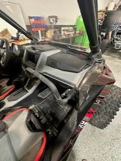
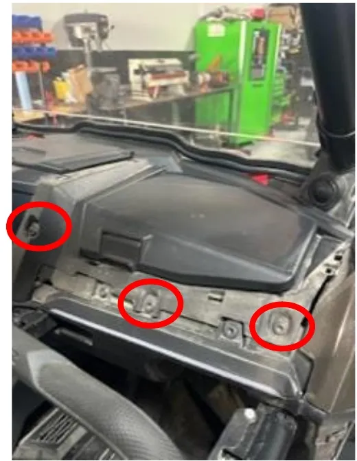
Remove the plastic shroud around the glovebox. Remove (3) T-40 screws.
- Step 2
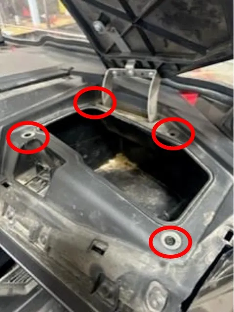
Remove (4) T25 screws holding the glovebox in. Slide the glovebox underneath the dash and remove.
- Step 3
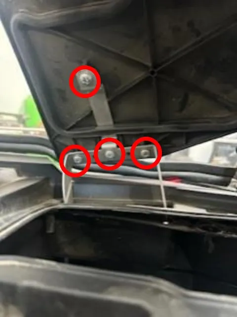
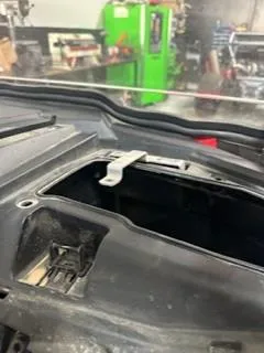
Remove (4) Philip screws from the glovebox door. Remove the door.
- Step 4
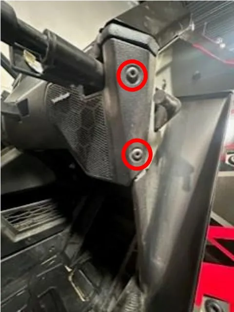
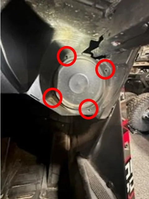
Remove the speaker faceplate, (2) T-40 screws. Remove (4) T-20 screws holding the speaker in.
- Step 5
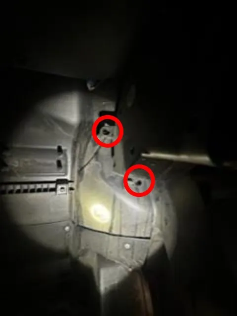
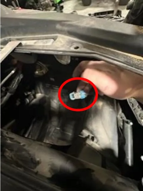
Remove (2) T-20 screws holding the rear of the speaker to the front firewall. Unplug the speaker electrical connector through the glove box access panel.
- Step 6
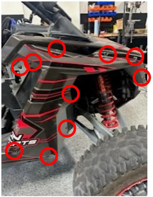
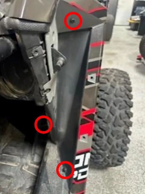
Remove the front passenger fender/panel. (11) T-40 screws and (3) push darts.
- Step 7
Remove the upper hood. (2) T-40 screws. Remove the lower hood (1) T-40 screw.
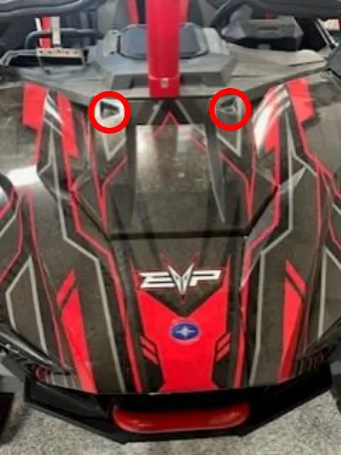
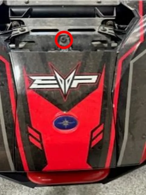
- Step 8
Remove the passenger side hood panel. (3) T-40 screws and (1) push dart.
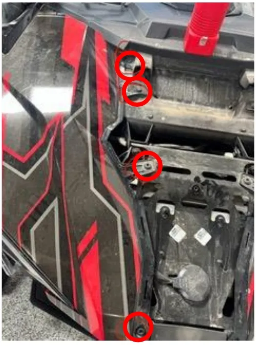
- Step 9
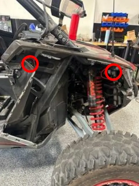
Remove the 10mm nut holding the antenna through the dash. Remove (1) T-40 screw and (1) push dart. Can remove passenger side hood.
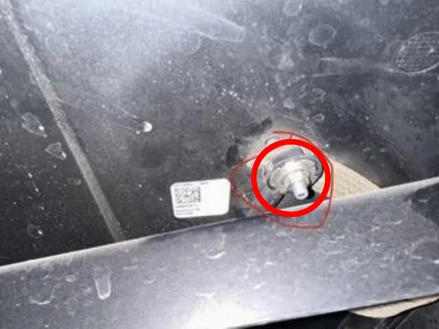
- Step 10
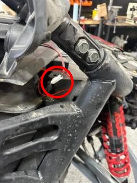
Slide the rubber A-pillar boot up the cage rail. Unplug the tweeter speaker connector. Remove (1) T-40 screw holding the upper passenger dash on.
- Step 11
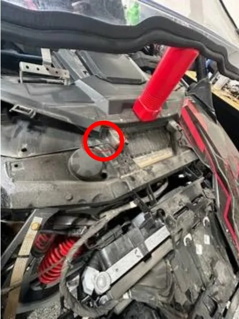
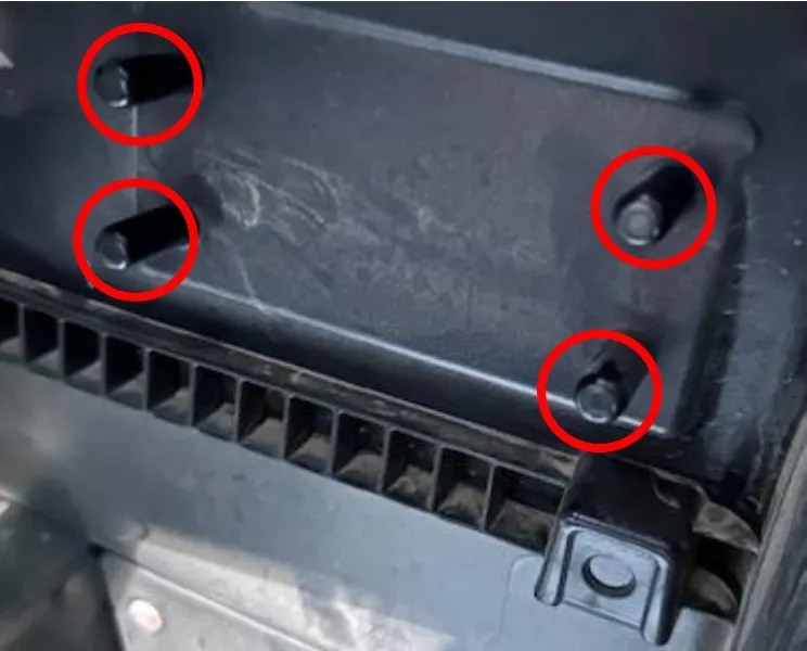
Cut/Grind the (4) plastic tabs off on the front firewall located underneath the dash.
- Step 12
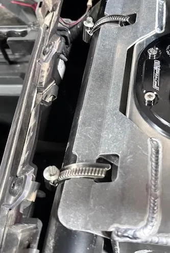
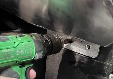
install fuel tank and loosely install the two hose clamps on upper dash tube. Push up on bottom of tank and drill the 3 holes using the 21/64 drill bit.
- Step 13
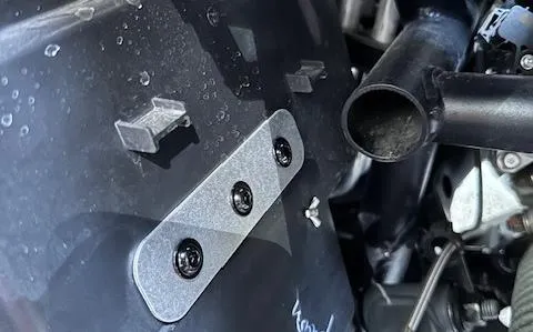
Install the (3) 8mm bolts with locknuts and tighten. Bolt head on outside of firewall. Tighten the hose clamps.
- Step 14
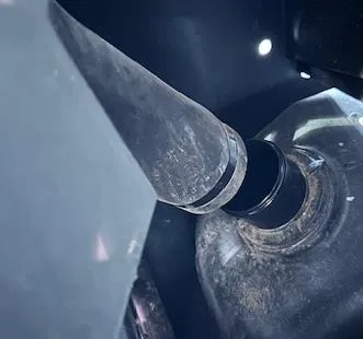
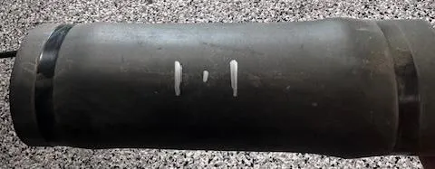
Remove passenger seat and rear firewall. Locate the filler neck, remove both hose clamps. Make a mark in the middle of the tube, cut off 1/2" on both sides of the tube.
- Step 15
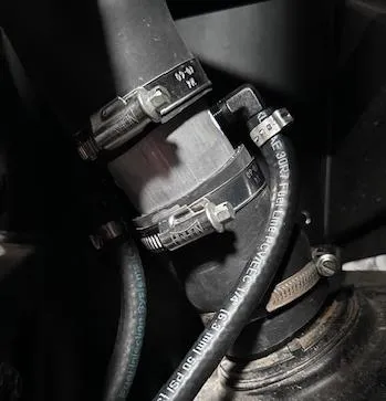
Install the aluminum filler in the middle of the rubber filler neck. Tighten with supplied hose clamps. Make sure the barbs are facing down and orientation is correct. Reinstall to tank. Install one end of each 112” fuel hose to the barbs and use supplied pinch clamp to tighten.
- Step 16
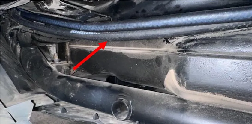
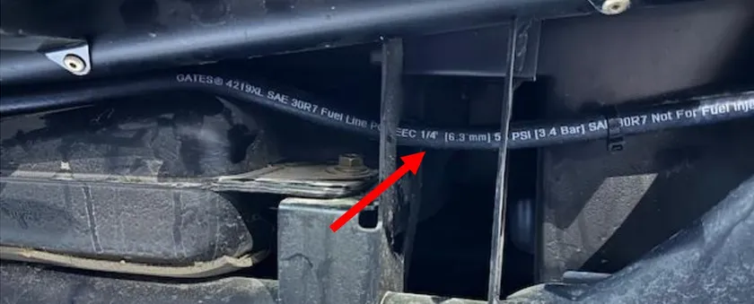
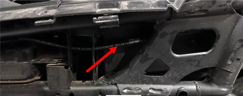
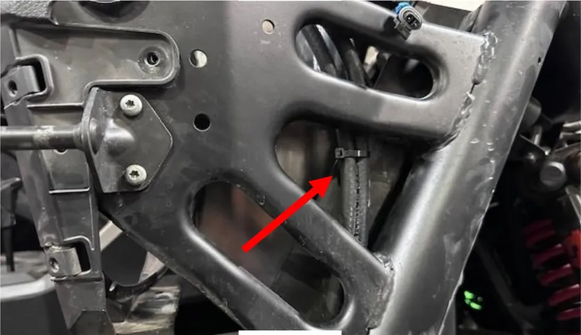
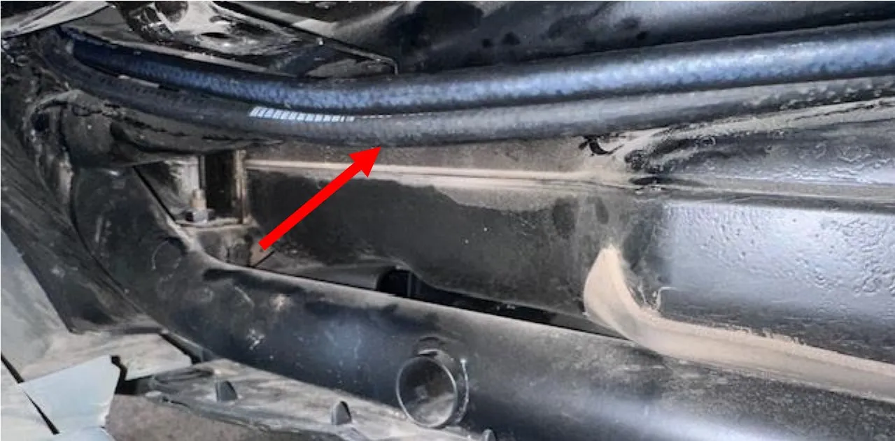
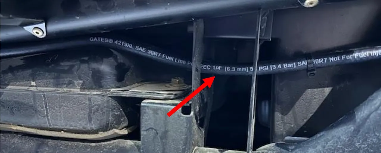
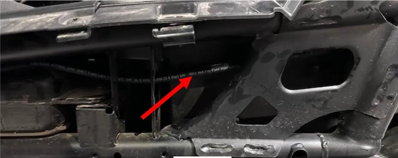
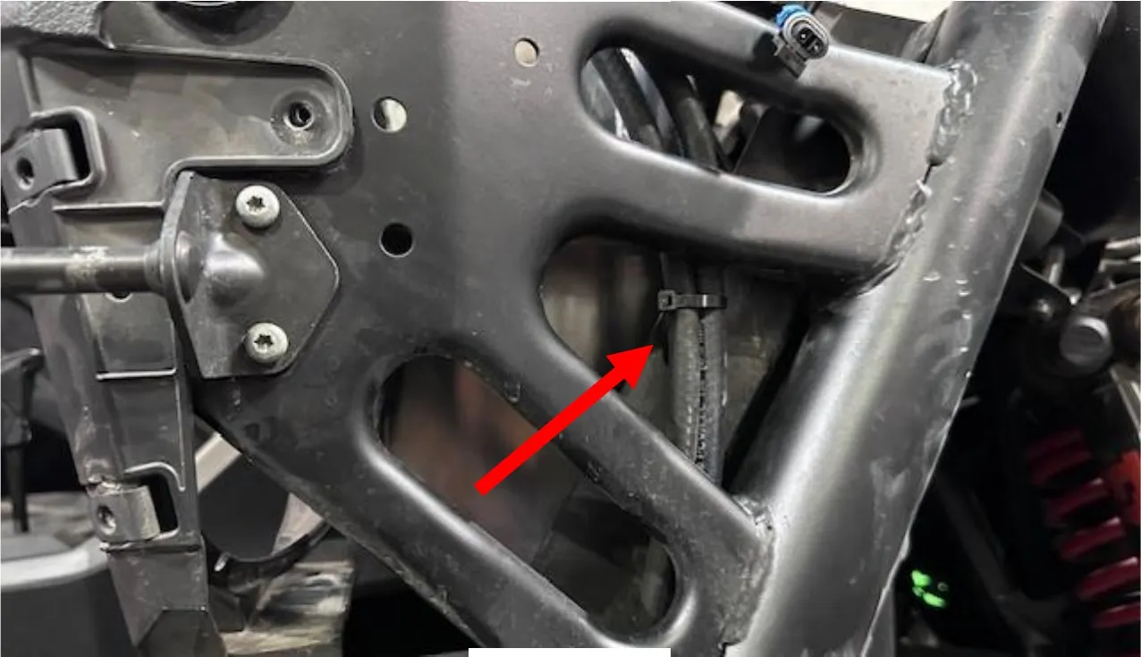
Route both fuel hoses underneath the cab, through the frame up to the fuel cell. Zip tie where needed.
- Step 17
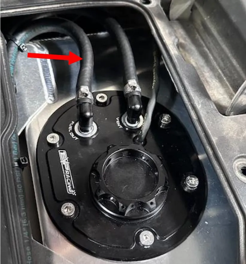
If you have excess hose (2-seater), trim both hoses to length and install onto the (2) barbs located on the fuel hat. Use supplied 13.3mm pinch clamps to secure. Orientation does not matter, both hoses run to the same adaptor. Install the one-way check valve in line on the fuel outlet hose. Use supplied 13.3mm pinch clamps to fasten down.
- Step 18
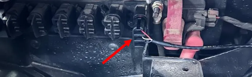
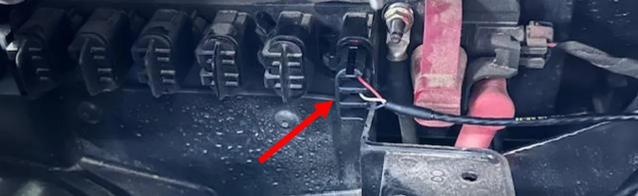
Connect the relay harness to the fuel cell connector. Plug the other end into the bus bar.
- Step 19
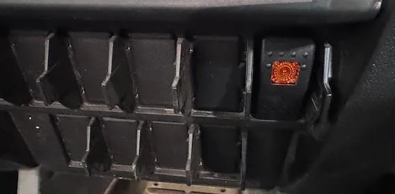
Install the auxiliary rocker switch into a blank location on the dash.
- Step 20
Fill the fuel cell and transfer fuel. Check for leaks.
- Step 21
Reinstall all plastic except the inner glove box tray or subwoofer.
Need technical support?
Submit a ticket with your vehicle and what you're seeing, and our support team will get back to you.
