 BUY NOW, PAY LATER. Starting at 0% APR


This is a high-performance upgrade! Although we have gone through great lengths to build safety into the upgrade turbo system, the fact is installing any upgrade / turbo system requires care in both operation and installation. Poor fuel, improper setup or any number of things that are done incorrectly can damage your engine!
Polaris Pro R Paragon-54 500 Turbo Upgrade System
Installation instructions for the Pro R Paragon-54 500 Turbo Upgrade System on the Polaris Pro R (RZR) (SKU 604FP0119). Parts, tools, and full procedure.
Before you start
Note
Expect 24–48-hour turnaround from the time we receive your ECU for unlock. Please send your ECU to EVP WI headquarters. Create your Maptuner/CodeShooter account before starting the project.
- You have likely voided the sound and exhaust emission standards of your country if applicable.
- This upgrade is intended for OFFROAD and RACING use only.
- This is a performance upgrade which will VOID your engine warranty especially if installed incorrectly or operated without regard to your instruments.
- The fuel requirements must be adhered to. Poor fuel can destroy an engine in seconds.
- Evolution Powersports bears no responsibility for damage caused to your vehicle by the installation of EVP products. The warranty on big turbo kits is 30 days from the date of purchase. Evolution Powersports, at its discretion will determine whether a part meets the warranty requirements. In no case is there any warranty from EVP for your vehicle or vehicles drivetrain. Although we have been careful to supply you with the highest quality parts possible, we assume no liability for damage to the vehicle or personal injury from installing or using any of our products.
- The installation of this kit is technical and mechanical in nature with many opportunities to make mistakes – mistakes that can be very costly. If you are not qualified to install this kit, bring your vehicle to one of our qualified installation centers to do the installation.
- This kit will make your vehicle faster, climb higher and accelerate more quickly and take a longer distance to brake than a stock tuned vehicle. If you are not capable of controlling the vehicle with the added performance, do not install the kit.
- High boost is hard on spark plugs – they must be changed frequently. If you experience misfire issues – Gap and replace the spark plugs.
- A full exhaust and clutching are required for this kit and can be purchased separately.
- Do not ever allow a child or an unqualified driver to operate this vehicle.
In the box
Parts and tools
Parts Included in Paragon 54-400 Turbo Upgrade System
| 604FP0075 | Pro R Paragon 54/68 Black Turbocharger Assembly |
| 604FP0076 | Pro R Paragon Installation Kit |
| 100FP0186 | Pro R Triple Fan Kaizen Intercooler Assembly |
| 953RU0485 | Pro R Triple Fan Intercooler Hardware Kit |
| 100RP0154 | Pro R Charge Tube Kit, Black |
| 953RU0421 | Pro R Turbocharger Charge Tube Hardware Kit |
| 203FP0110 | Pro R Turbocharger Air Intake Kit |
| 804FP0259 | Pro R OEM Coolant Tank Relocation Kit |
| 953RU0486 | Pro R Turbocharger Boost Control Kit |
| 803FU0011 | Pro R Catch Can Kit |
| 100FP0187 | Pro R Blow Off Valve 2.0 (BOV) Kit |
| 300FP0374 | Pro R Turbocharger Header/Exhaust System |
| 604FP0078 | Pro R Turbocharger Hardware Installation Kit |
| 004FP0361 | Pro R Turbo Bench Power Flash, CAN Unlock |
| 502FU0018 | 1300cc Injector, ID1300-XDS Uscar, 34mm Length, 14mm top, 14mm lower, set of 4 |
| 603FP0005 | Pro R External Wastegate Assembly |
| 705RU0029 | 3 Bar MAP Sensor |
| 925FP0184 | Pro R Exhaust Facia Trim Plate |
| 102FP0007 | Pro R Intercooler Mount |
| 500FP0044 | Pro R Rising Rate High Pressure Fuel Pump Kit |
| Level | Tunes | Max Boost (psi) | Spark Plug Gap | Spring | Operating RPM | Engine HP |
|---|---|---|---|---|---|---|
| P54-330 | 91 | 6-7 psi | .016 - .018 | Pink (7) | 8200-8450 | 330CHP, 271WHP |
| P54-400 | 110 | 12-13psi | .016 - .018 | Pink (7) | 8200-8450 | 400CHP, 328WHP |
| P54-500 | E85 | 15-16psi | .016 - .018 | Pink (7) | 8200-8450 | 500CHP, 410WHP |
Required Parts (Sold Separately)
- EVP calibrated Tapp primary clutch
- EVP calibrated STM secondary clutch
- AFR Module
- Oil Change Kit (Recommended)
- Engine Coolant
- Compressed air and parts cleaner
- P90X primary clutch puller
Procedure
Pro R Disassembly
- Step 1
Remove the (4) bed screws using a T-40. Remove the bed.
- Step 2
Remove the passenger and driver seat, if a 4-seater remove the rear seats.
- Step 3
Remove both firewall panels, (6) 1/4-turn fasteners.
- Step 4
Cut all zip-ties holding the taillight harness and rear-view camera. DO NOT remove the clips from the panels, this way you can reuse all OEM clips and supplied zip-ties in the hardware kit.
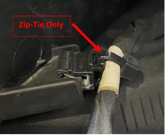
Zip-Tie Only - Step 5
Unplug both rear taillights and camera.
- Step 6
Remove the lower rear valance around the muffler tips. Use a T-50 socket.
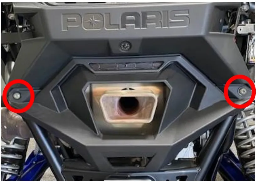
- Step 7
Remove the upper rear valance with taillights. (4) T-40 screws and (6) push darts. (2) push darts are tucked underneath the rear fenders.
- Step 8
Remove the cold air intake tube (bed to airbox tube) and intake tube (airbox to throttle body). Remove the crankcase breather tube from the intake tube. (4) worm drive clamps total.
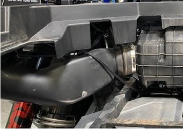
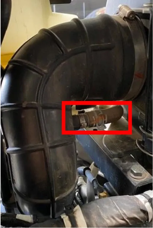
- Step 9
Remove the engine belly pan using a 10mm socket. (8) screws and oversized washers.
- Step 10
Remove the coolant reservoir cap. Locate the water pump housing (above the oil filter) and remove the 4mm Allen plug. Place a catch pan underneath the vehicle. (figure 5).
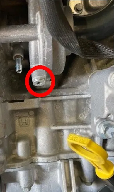
Fig. 5 - Step 11
Remove the (2) 10mm screws holding the airbox in place. Two tabs will be located underneath the airbox.
- Step 12
Remove (2) T-40 screws holding the coolant reservoir in place. Remove all hoses from the coolant reservoir.
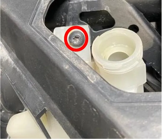
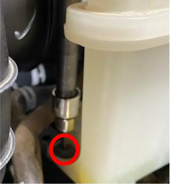
- Step 13
Remove the bed frame hardware (4) 13mm bolts and (1) T-40 for the CVT boot support bracket.
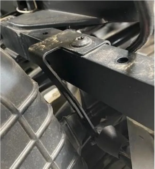
- Step 14
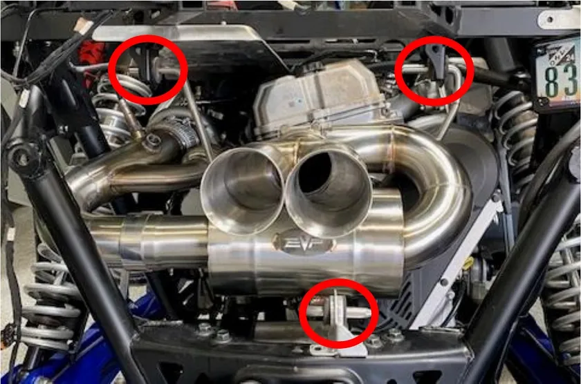
Remove (2) 14mm bolts holding the muffler and header pipe together. Remove the muffler by sliding it out of (3) rubber gromets (towards the left side of the vehicle. Gromets shown below.
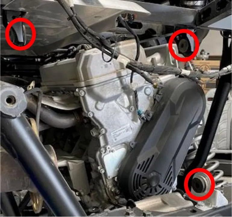
- Step 15
Remove the airbox and bed frame. Cut all zip-ties holding the engine harness to the bed frame.
- Step 16
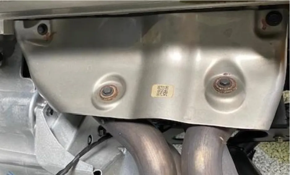
Remove the header heat shield. (4) 10mm screws.
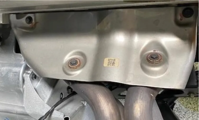
- Step 17
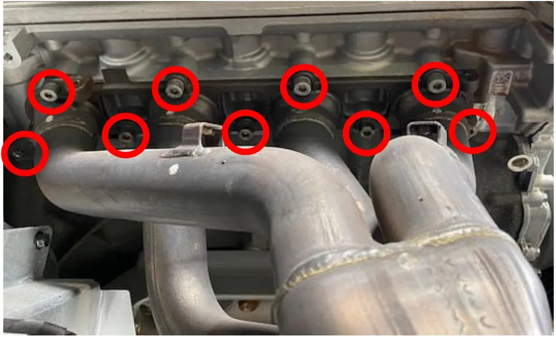
Remove (9) 6mm Allen screws holding the header to the engine block. Unplug the 02 sensor from the engine harness. Remove the header.
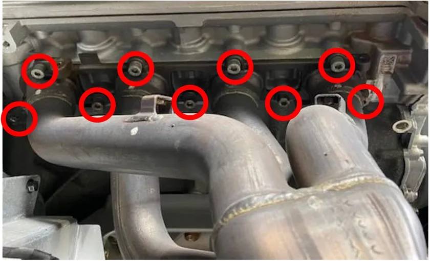
- Step 18
Remove the alternator belt cover. (7) 10mm screws.
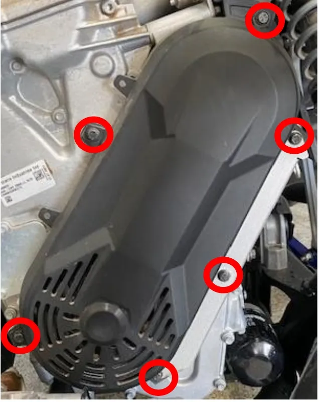
- Step 19
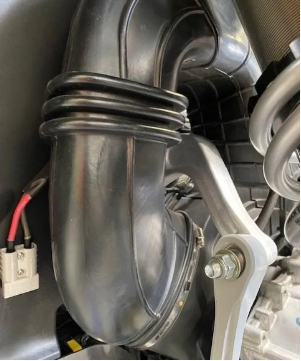
Remove the CVT box breather. (1) worm drive clamp.
- Step 20
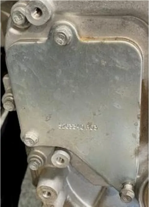
Remove the chain tensioner access panel from the timing chain cover, using an 8mm socket.
Procedure
Pro R Reassembly
- Step 1
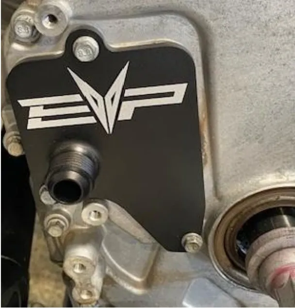
Install supplied EVP chain tensioner cover. Torque the OEM hardware to 80 in-lbs. Reinstall the alternator belt cover.
Procedure
Pro R Intercooler
- Step 1
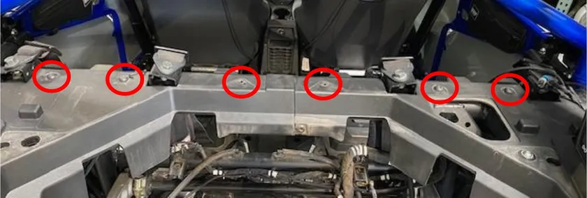
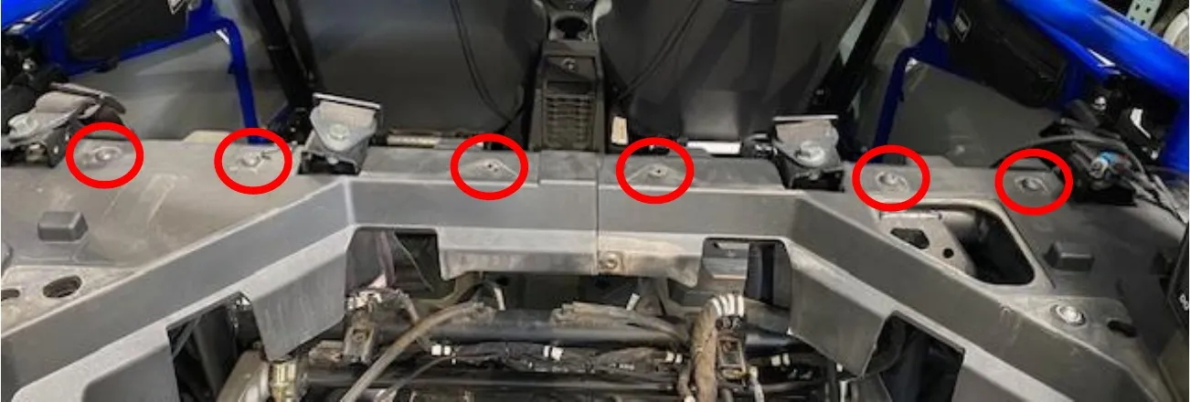
Remove (6) T-40 screws on the back cargo area. See photo below.
- Step 2
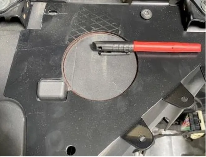
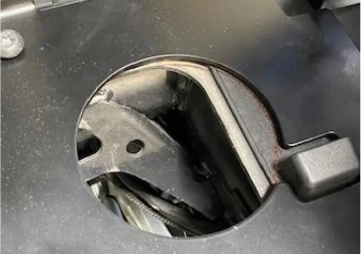
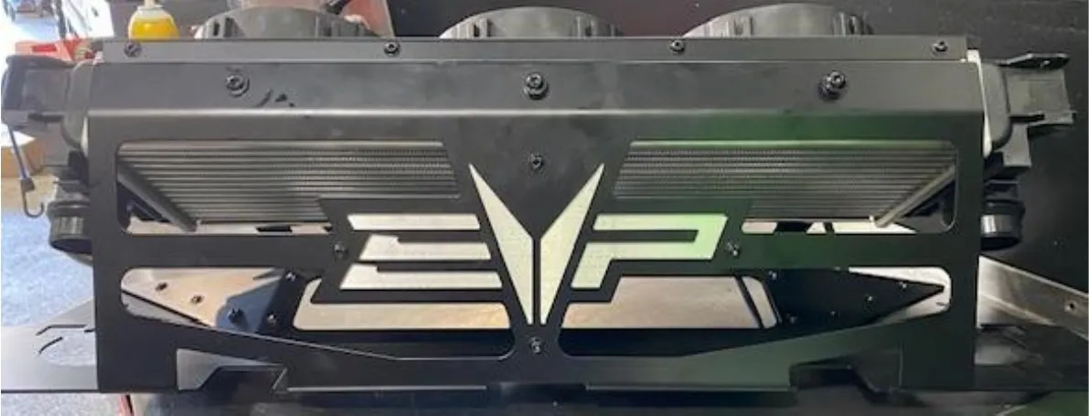
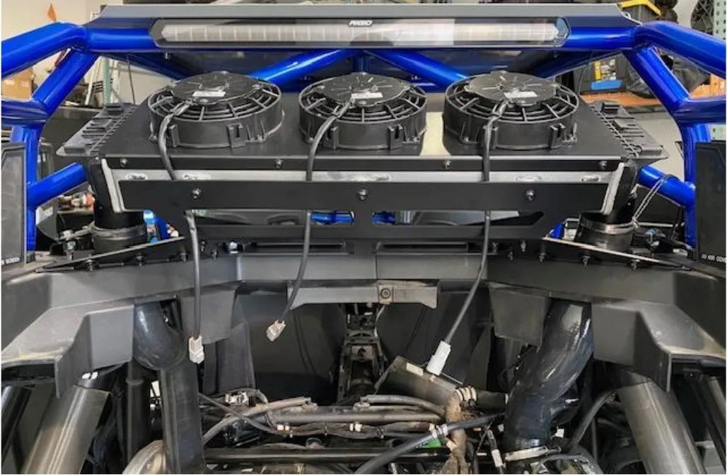
Install the intercooler cage onto the vehicle. Hand tighten a few T40 screws to hold it secure. With a silver sharpie, outline both circles onto the plastic. Remove the cage. With a 3.50” whole saw or Dremel with a carbide bit, cut out both holes. Use fine grit sandpaper and a heat gun to clean up the burs.
- Step 3
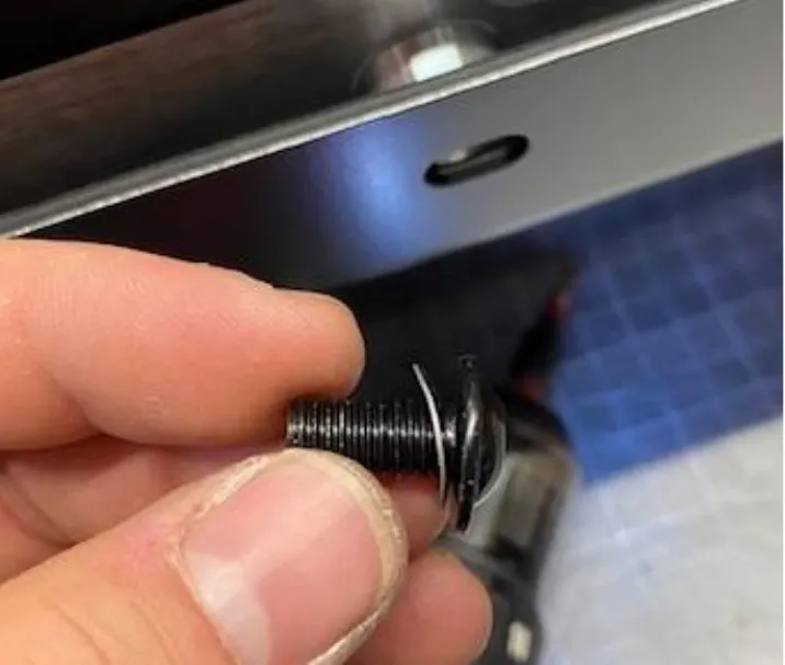
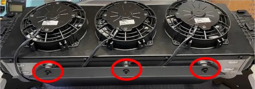
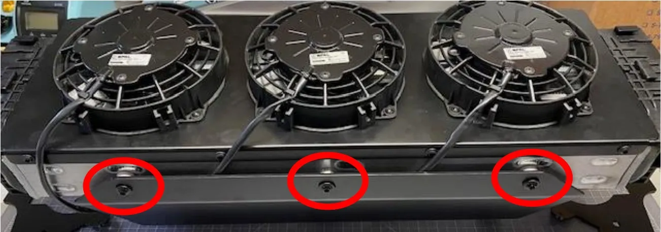
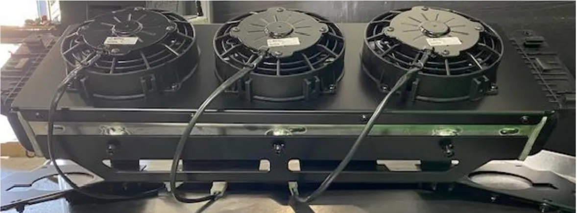
Install the intercooler onto the mount. Use supplied M8-16mm flanged screws with spring washers. A total of (6). Make sure the fan harnesses go inside the mount. (photo taken on work bench).
- Step 4
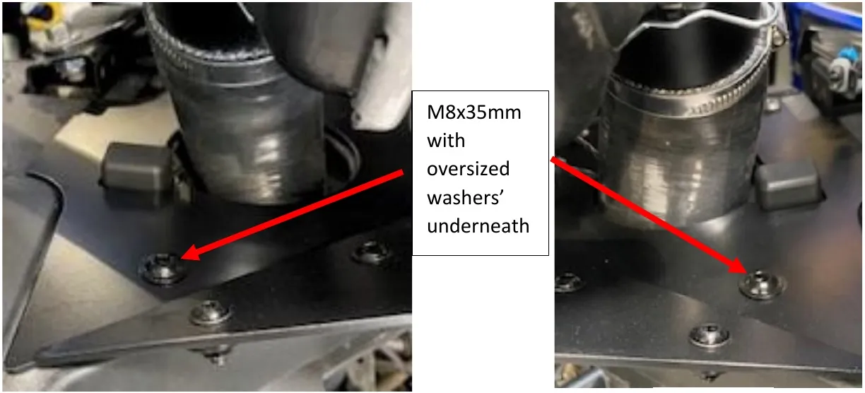
Install the intercooler and cage onto the vehicle. Use OEM hardware to secure the intercooler cage to the vehicle. Use (2) M8x35mm button head, (2) oversized washers and nyloc nuts to secure the rear of the intercooler cage.
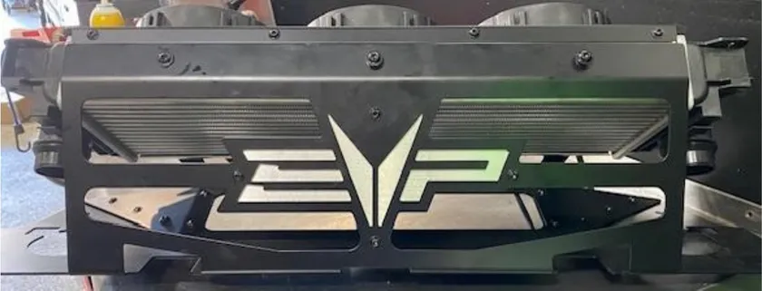
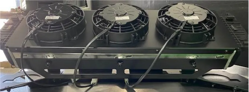
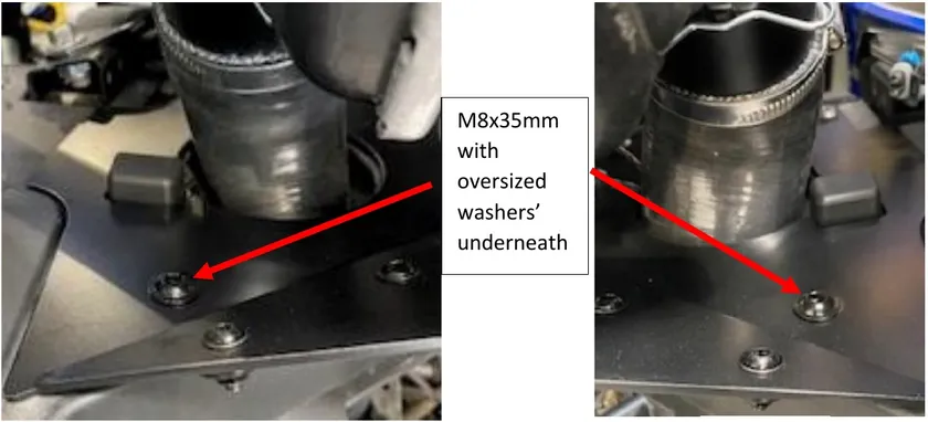
M8x35mm with oversized washers’ underneath
Procedure
Pro R Header
- Step 1
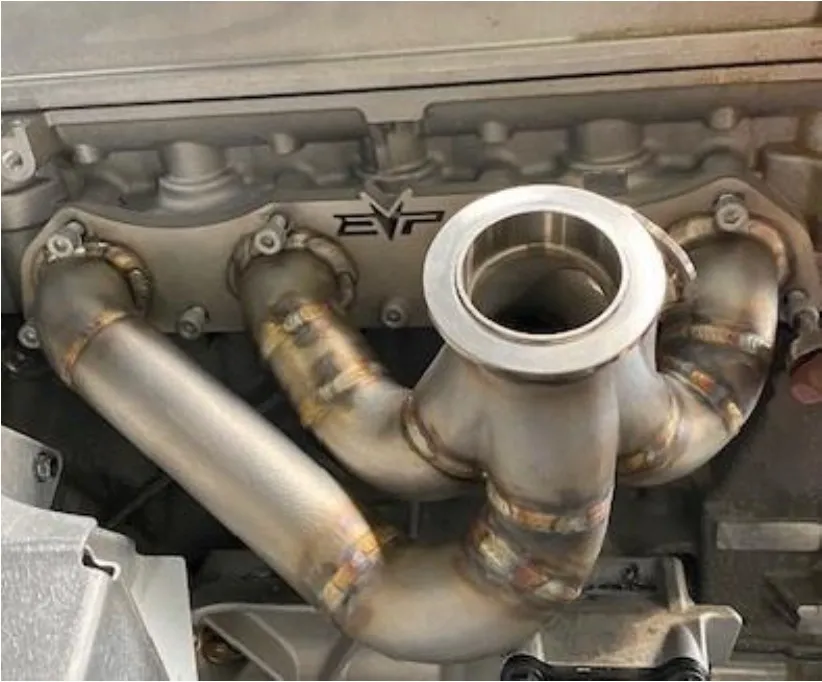
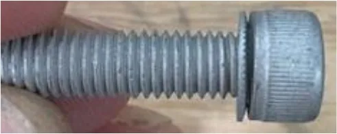
Make sure all debris is off exhaust ports on the cylinder head, install supplied header gasket, header pipe, (9) M8x30mm screws with (9) conical washers. Torque to the sequence below.
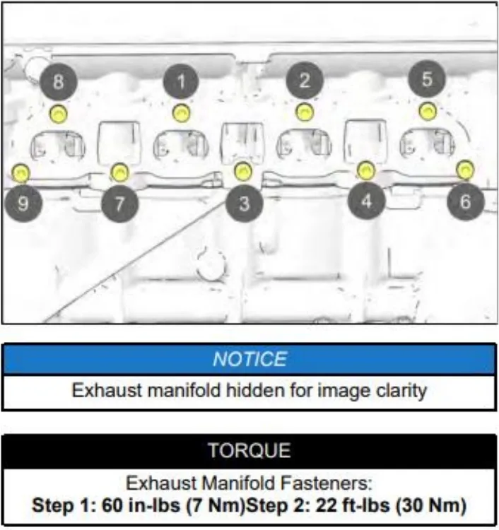
Exhaust Manifold Fasteners: Step 1: 60 in-lbs (7 Nm) Step 2: 22 ft-lbs (30 Nm) - Step 2
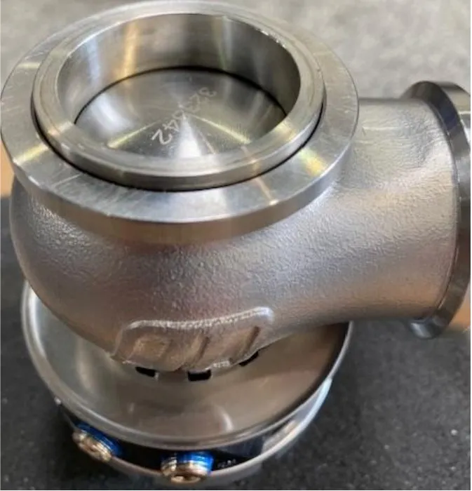
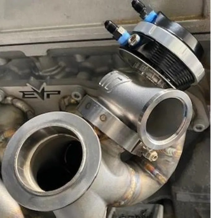
Install the 41mm OD stainless steel sleeve into the intake cylinder on the wastegate. Install onto the header with a 204221 clamp. Apply anti seize on threads of the clamp. Keep clamp loose for now.
- Step 3
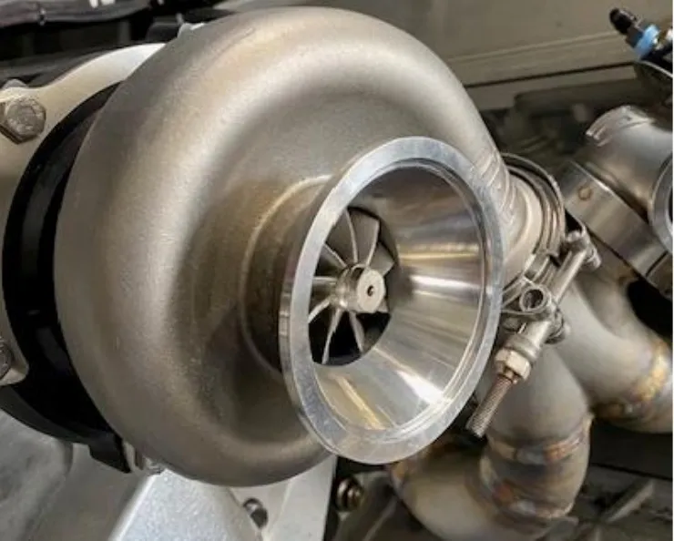
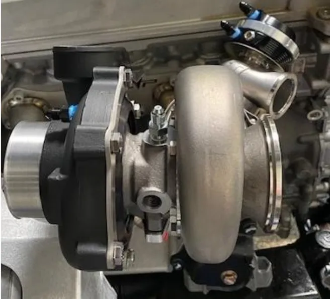
Install turbocharger to the header using a 215221 clamp. Apply anti seize on threads of the clamp. Keep clamp loose for now.
- Step 4
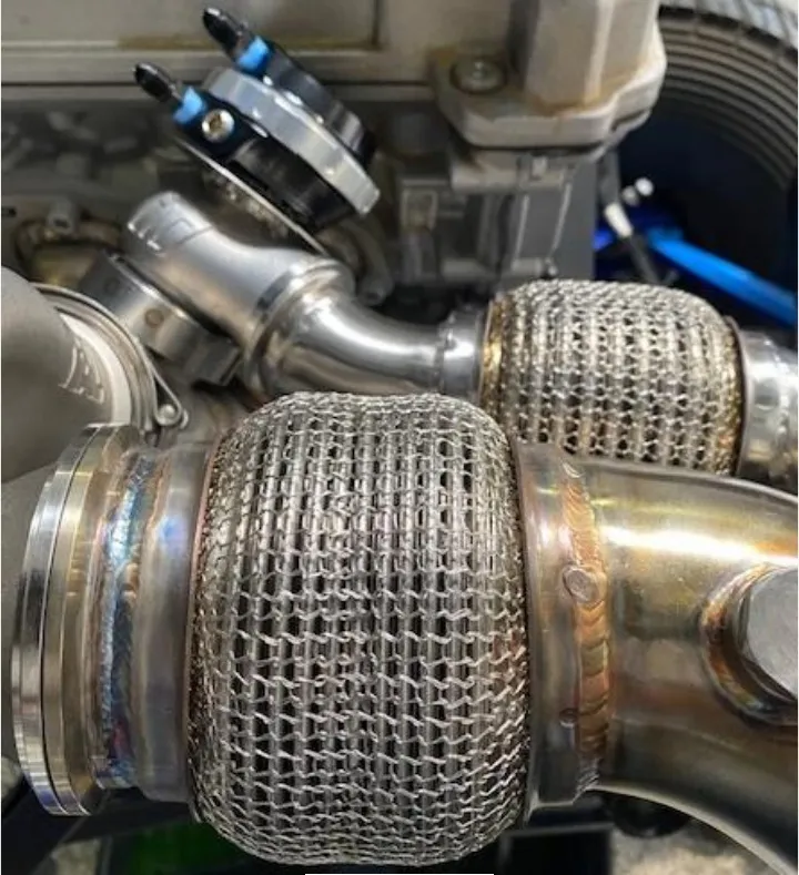
Install the mid-pipe to the turbocharger and wastegate dump. Apply anti seize on the threads. Leave clamps loose for now. Wastegate dump to mid-pipe will use clamp 105212. The turbocharger to mid-pipe will use clamp XXXXX.
- Step 5
Leave the mid-pipe hanging for now, you will connect the muffler later when the bed frame gets reinstalled.
Procedure
Turbocharger Oil Lines
- Step 1
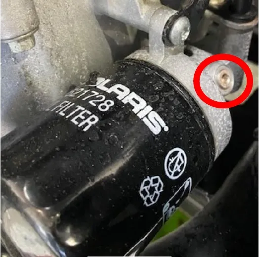
Locate the oil filter, remove the 5mm plug out of the oil filter housing.
- Step 2
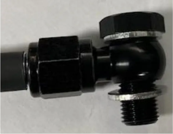
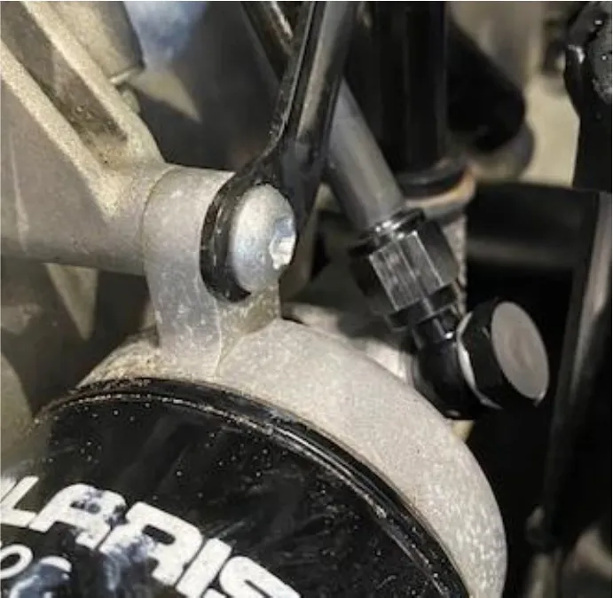
Locate the 60” oil feed line. Install supplied fire sleeve onto the oil feed line. Install supplied banjo bolt and washers on the straight fitting. Install it onto the oil filter housing. DO NOT OVER-TIGHTEN.
- Step 3
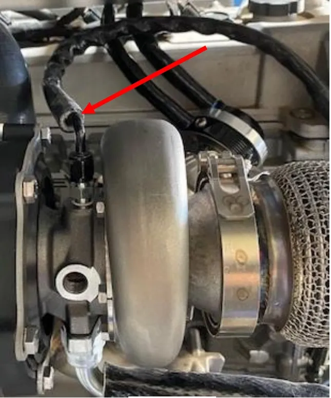
Route the 90-degree fitting to the oil feed on the turbocharger.
- Step 4
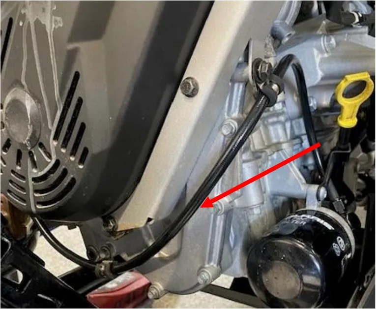
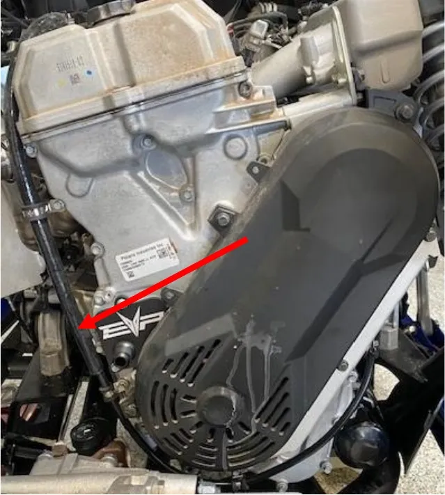
See oil feed line routing below, use supplied 5/16” & 1/2" P-clamps to hold the oil line around the timing chain cover.
- Step 5
Locate the oil drain hose with (2) 90-Degree fittings. Install fire sleeve onto the oil drain hose. Install one end to the oil drain plate located where the timing chain access panel is.
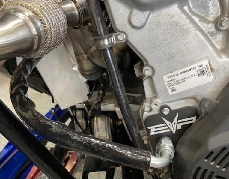
- Step 6
Install the other 90-degree fitting to the oil drain located on the turbocharger.
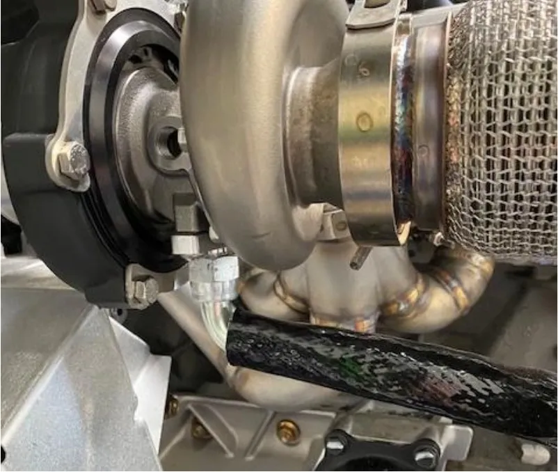
Procedure
Pro R Charge Tube
- Step 1
Locate the airbox to turbocharger charge tube. Install the 1/2" plug into the crankcase vent port. Fasten with a 24.1mm pinch clamp. (Pre 10-24-2023 Figure 38). Turbocharger to intercooler charge tube will need a BOV plug installed with a 34.6mm pinch clamp. (Figure 39)
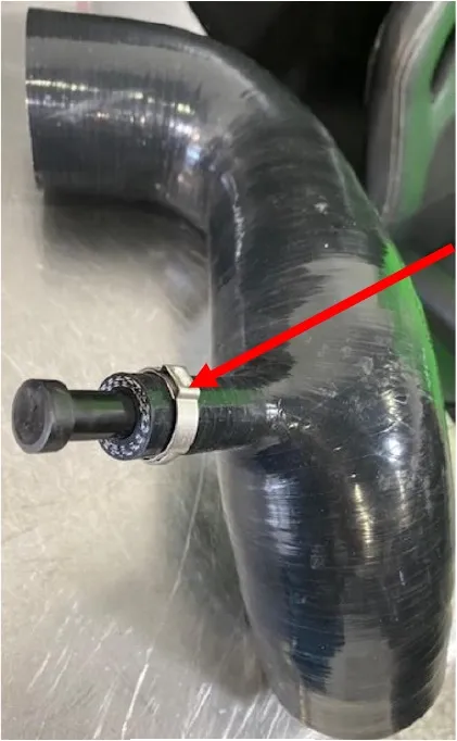
Fig. 38 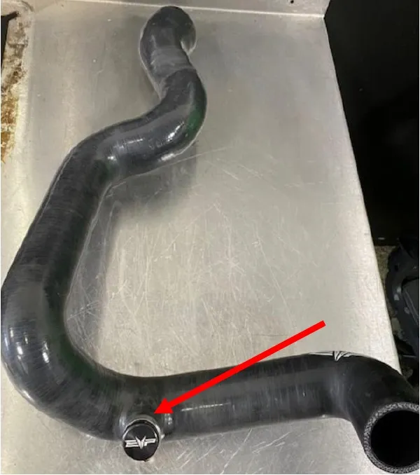
Fig. 39 - Step 2
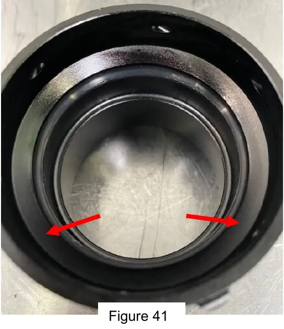
(PRE 1-7-2024 ONLY) Install the O-rings into the billet charge tube connectors. Apply dielectric grease to the O-rings. The O-rings are directional, install as shown below.

- Step 3
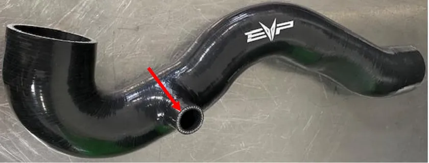
Locate the intercooler to throttle body charge tube. The blow off valve will be mounted in the port shown below.
- Step 4
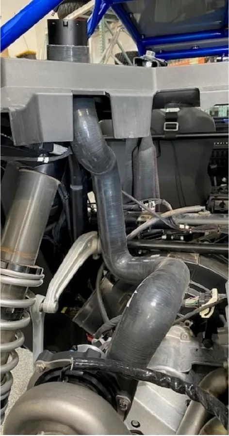
Install the turbocharger to intercooler charge tube. Once you have fit the silicone through the plastic. Use dielectric grease if needed. Fasten down with a 60-80mm worm drive clamp. Fastened the turbocharger side with a 50-70mm worm drive.
- Step 5
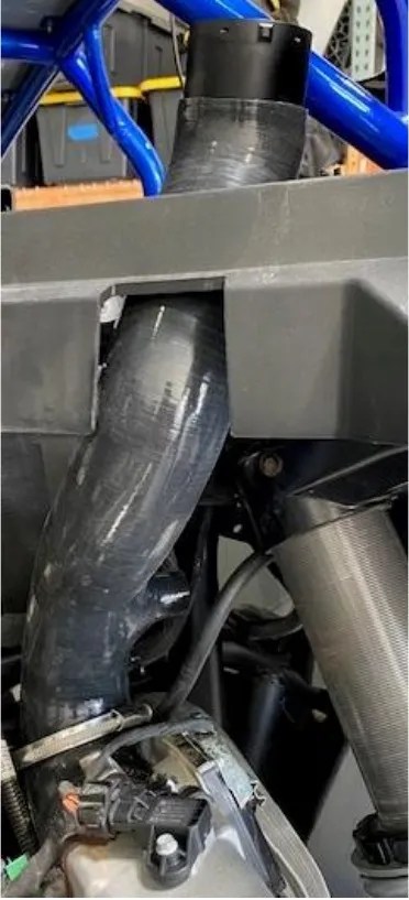
Install the throttle body to intercooler charge tube. Once you have fit the silicone through the plastic. Use dielectric grease if needed. Fastened down with a 60-80mm worm drive. Fastened down the throttle body side with a 70-90mm worm drive.
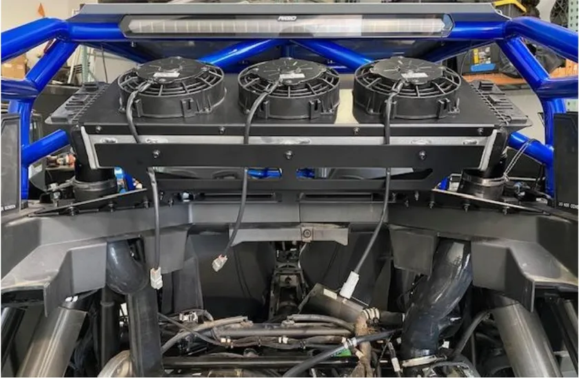
- Step 6
(PRE 1-7-2024 ONLY) Install the billet connectors to the intercooler. Use (3) cotter pins per each side.
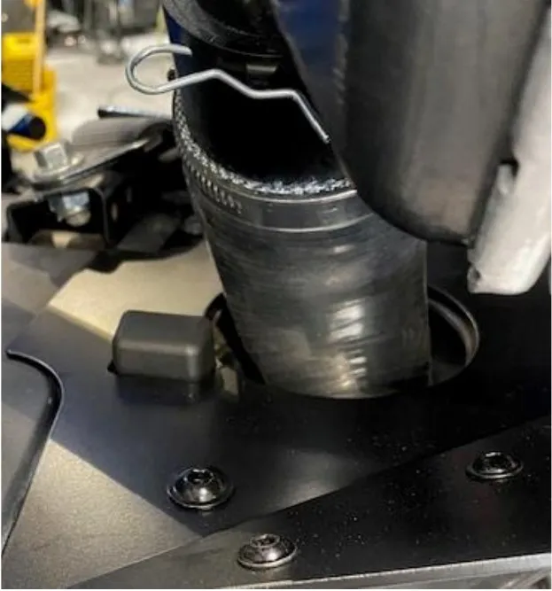
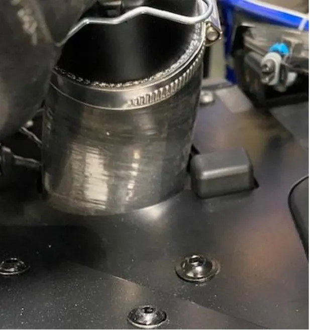
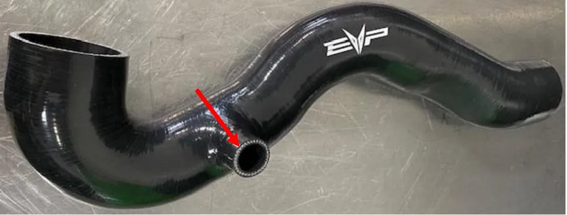
Procedure
Pro R Coolant Tank/ECU Removal
- Step 1
Located behind the passenger seat (if a 4 seater the rear passenger seat), remove the (4) push darts holding the sound dampener in.
- Step 2
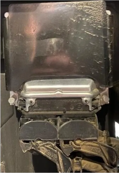
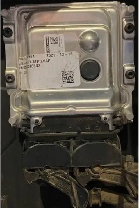
Located behind is the ECU. Remove the black clip. Remove the (4) T15 screws holding the ECU in place. Unclip the ECU connectors, left before the right.
- Step 3
Remove the bed to CVT ducting, (2) worm drive clamps.
- Step 4
Freely hold up the coolant reservoir bracket, keeping the EVP logo in line with the push dart hole and using the OEM existing hole for the bottom right Nutzert. (Figure 71-72).
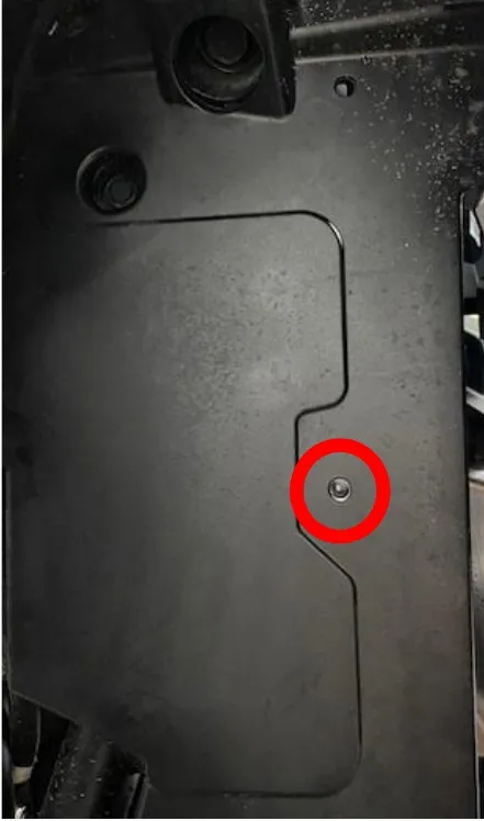
Fig. 71 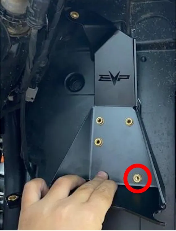
Fig. 72 - Step 5
Angle the bracket so you cannot see the 90-degree bend on the plastic. Figure 73 wrong, Figure 74 correct.
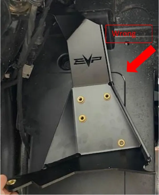
Fig. 73 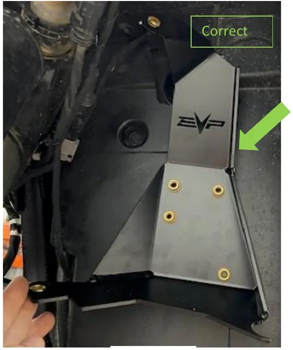
Fig. 74 - Step 6
Mark the (3) holes out with a sharpie. Cut the holes out with a 1/4" drill bit. Install the mounting hardware on the bracket side.
- Step 7
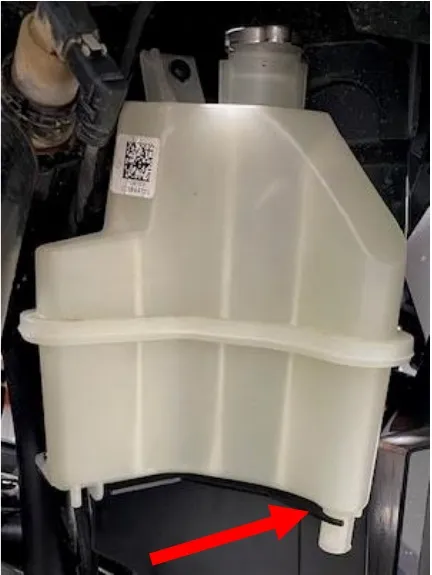
Mount the coolant tank. Make sure to mount the coolant tank inside the lower cutout.
Procedure
Pro R Coolant Tank/ECU Removal
- Step 6
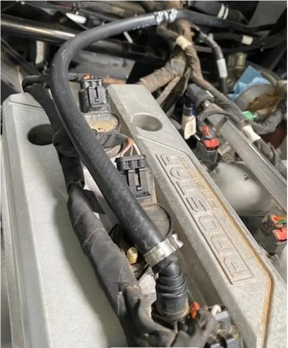
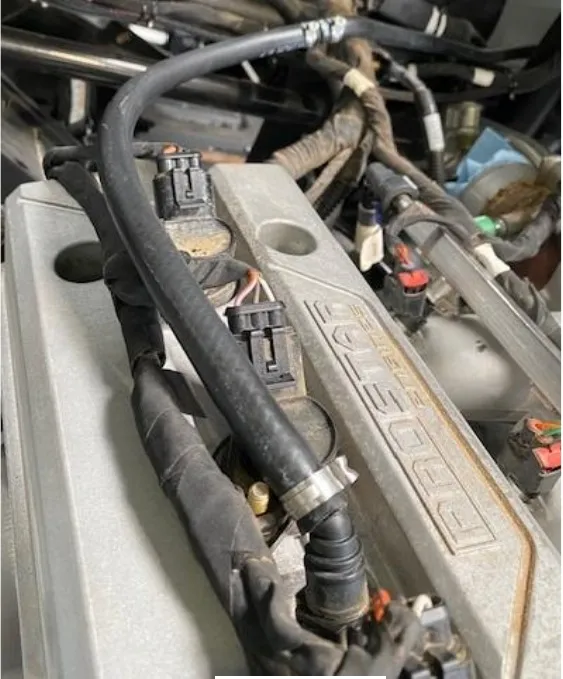
Cut the pinch clamp holding the valve cover water fitting on, remove the OEM hose from the valve cover fitting. Install the supplied 18” of 5/16” hose to the valve cover fitting. Use 15.7mm pinch clamp to secure.
- Step 7
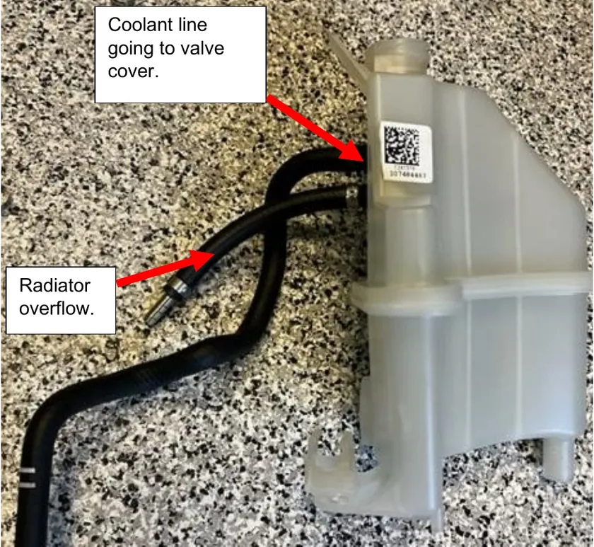
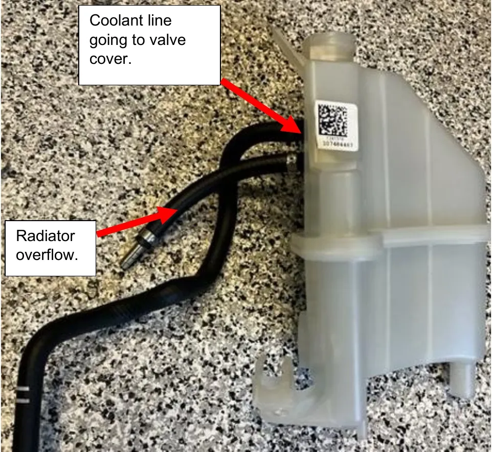
Install the OEM valve cover hose to the TOP barb on the coolant tank. Install the 8” piece of 5/16” hose on the BOTTOM barb for the radiator overflow. Install a 5/16 adapter to the end of the 8” piece of hose. Use 15.7mm pinch clamps.
- Step 8
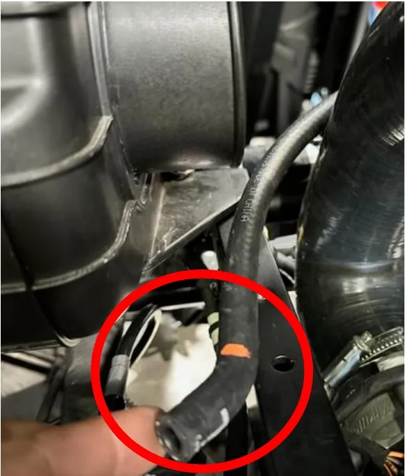
On the valve cover water hose, the part that was connected to the fitting, cut 1.0” or the 45-degree bend off.
- Step 9
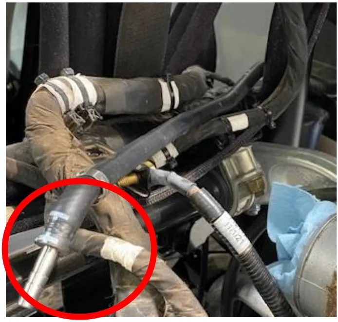
Insert a 5/16” adaptor into the valve cover hose and connect it to the 18” of hose coming from the valve cover. Use 15.7mm pinch clamps.
- Step 10
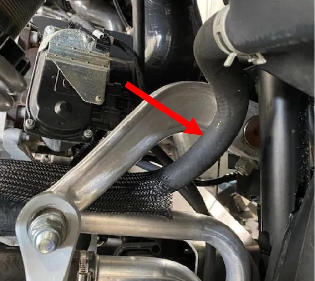
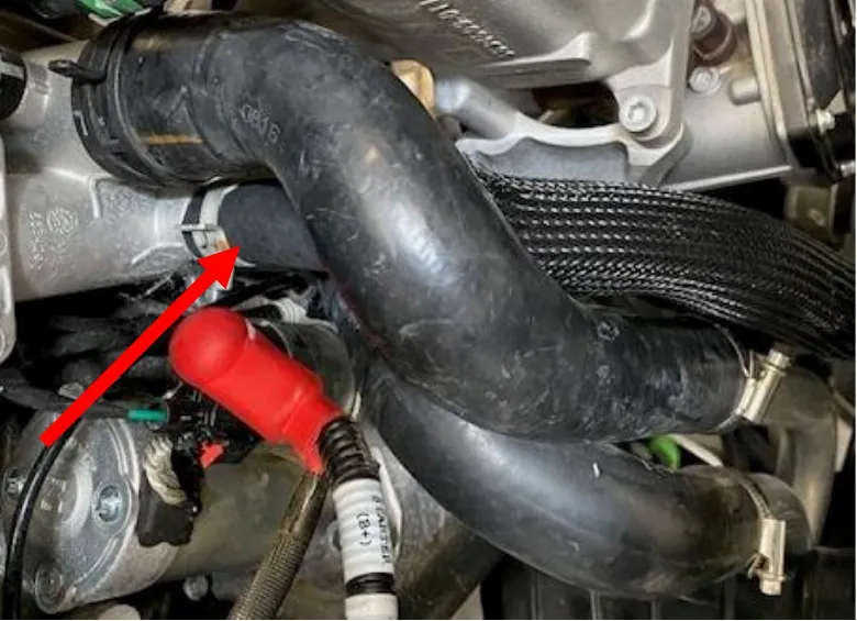
Install the supplied hose from the large barb on the coolant tank to the thermostat block. Reuse (2) self-tightening OEM clamps.
Procedure
Injector/MAP Senor Installation
- Step 1
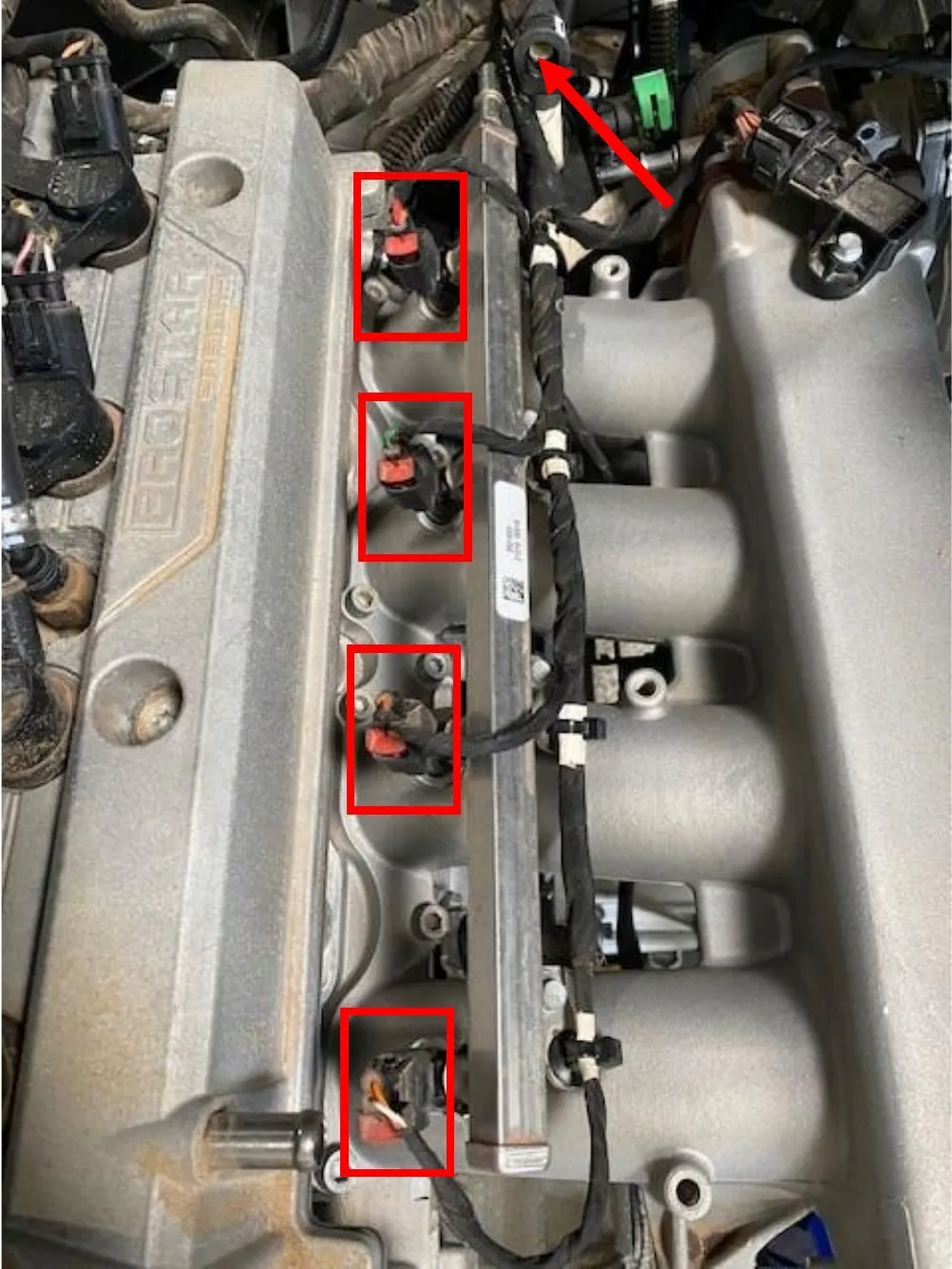
Remove (4) injector connectors, cut the zip-ties holding the injector harness to the intake plenum and remove from the fuel rail. Remove the blue clip and fuel hose connector from the fuel rail.
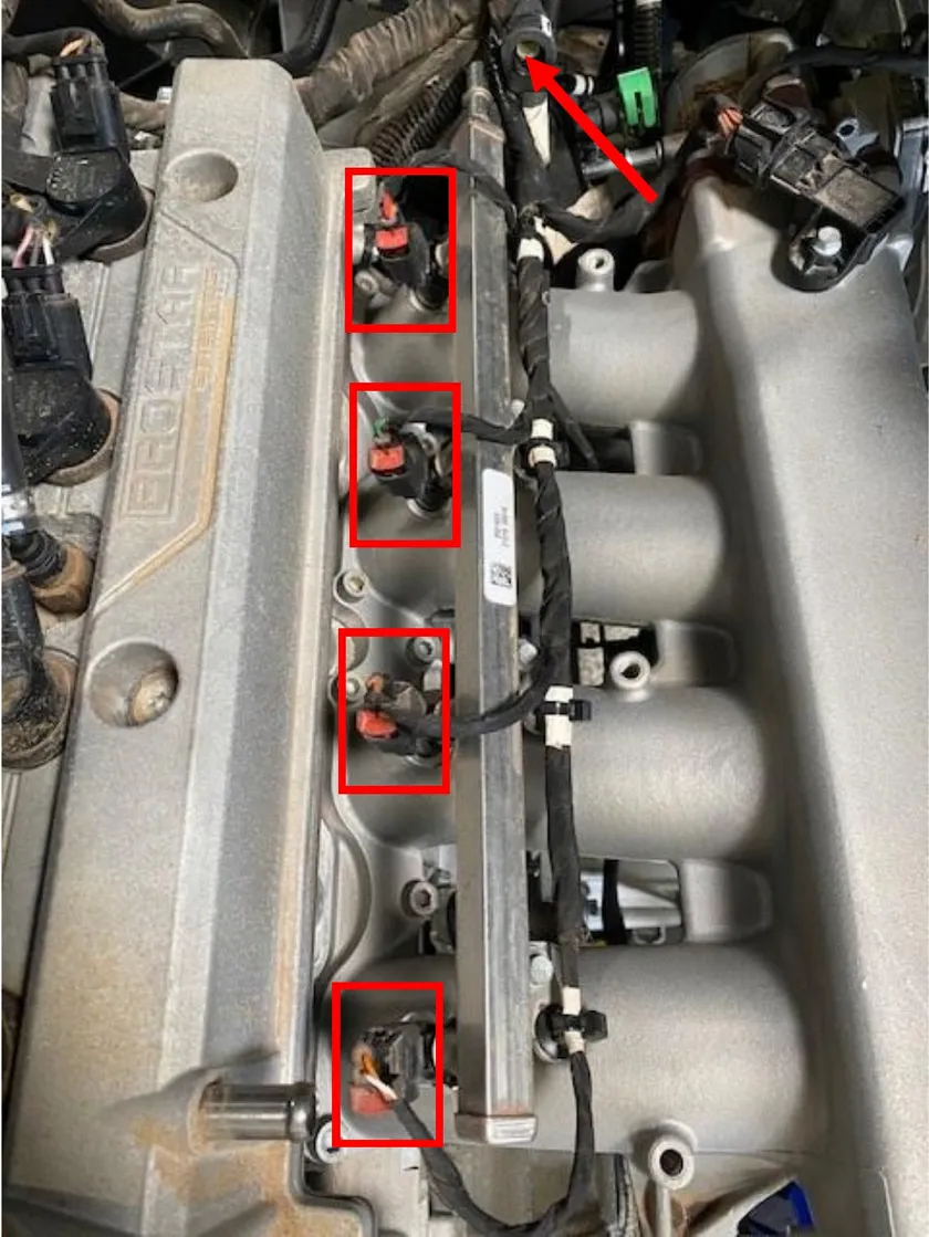 Note
clean intake plenum with compressed air, especially around the injector ports.
- Step 2
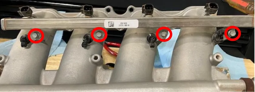
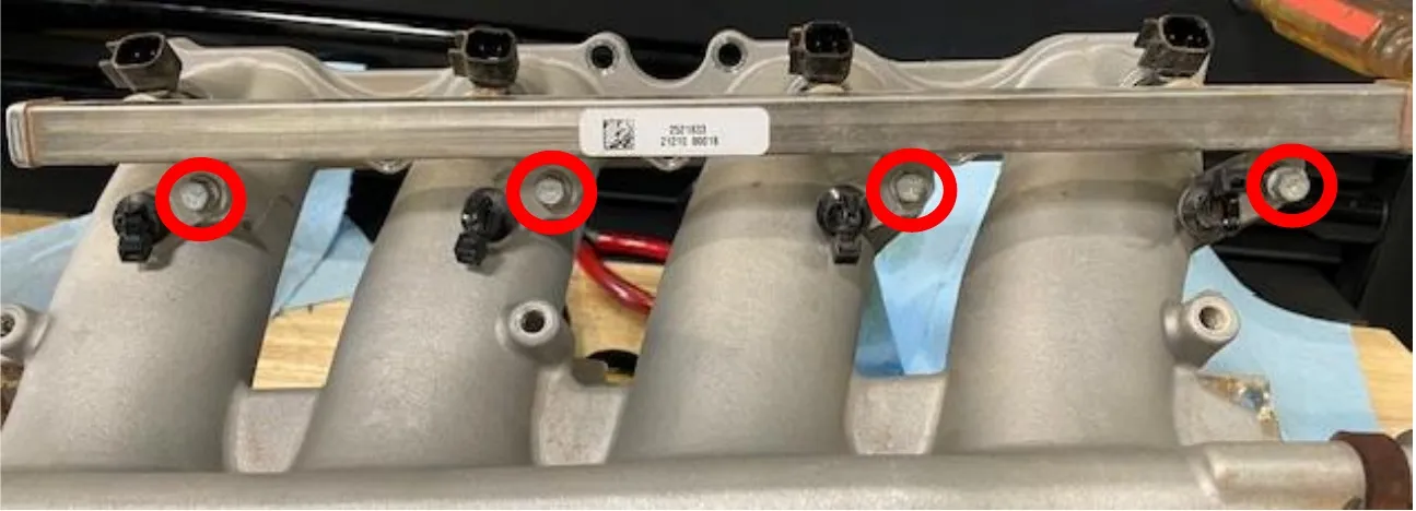
Remove the (4) 8mm screws holding the fuel rail to the plenum. Remove the fuel rail.
- Step 3
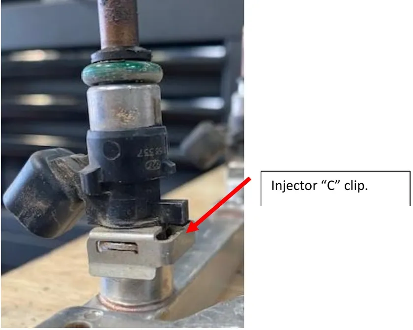
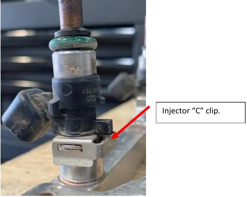
Remove the injector clips, remove the injectors. Blow out the fuel rail with all injectors removed.
- Step 4
Install the supplied (4) injectors. Apply dielectric grease to the O-ring on the injector. Reinstall the injector clip. Make sure the injector is properly seated. Torque fuel rail to 7 ft-lbs.
- Step 5
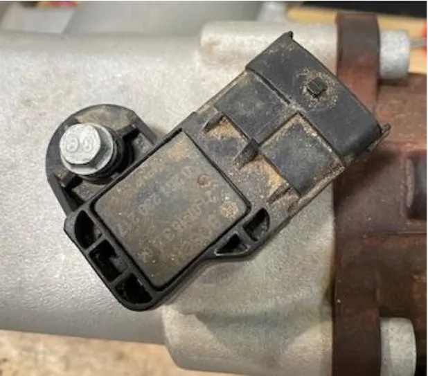
Remove the MAP sensor plug. Do NOT use a screwdriver. Remove OEM MAP sensor using a 8mm socket. Install the supplied MAP sensor, apply dielectric grease on the O-ring before installing.
- Step 6
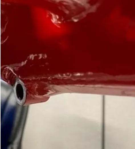
Remove the brass barb fitting on the bottom side of the intake plenum. Install the supplied M12 x 1/4" barb fitting.
- Step 7
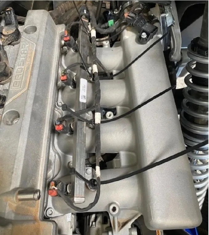
Reinstall the fuel line to the fuel rail (blue clip). Reinstall the OEM harness and injector connectors.
- Step 8
Install new zip-ties onto the plenum to hold the factory harness.
- Step 9
Re-gap the OEM (NGK-ZMR7A-10) spark plugs to 0.018”. Install the spark plugs back into the cylinder head. Torque to 9 ft-lbs.
- Step 10
Reinstall ignition coils and torque to 80 in-lbs. Reconnect all (4) ignition coils to the harness.
Procedure
Pro R Airbox (Pre 10-24-2023)
- Step 1
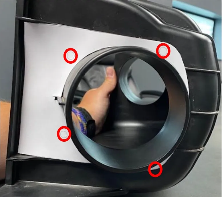
Locate the air filter adaptor template. Install it onto the outside of the airbox. Once aligned properly mark the (4) holes with a silver sharpie.
- Step 2
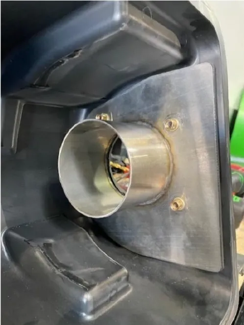
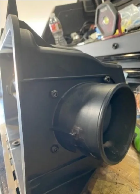
Use a 1/4" drill bit and drill out (4) holes. Fasten the bracket down with supplied (4) M6x16mm flanged head screws into the Nutzerts.
- Step 3
Reinstall the airbox (loosely) into the vehicle.
- Step 4
Reinstall the bed frame with OEM hardware.
- Step 5
Reinstall airbox hardware and engine harness clips. Use supplied zip-ties.
- Step 6
Install supplied air filter and pre filter into the airbox.
Procedure
Pro R Airbox (Post 10-24-2023)
- Step 1
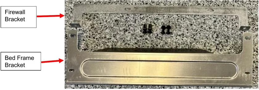
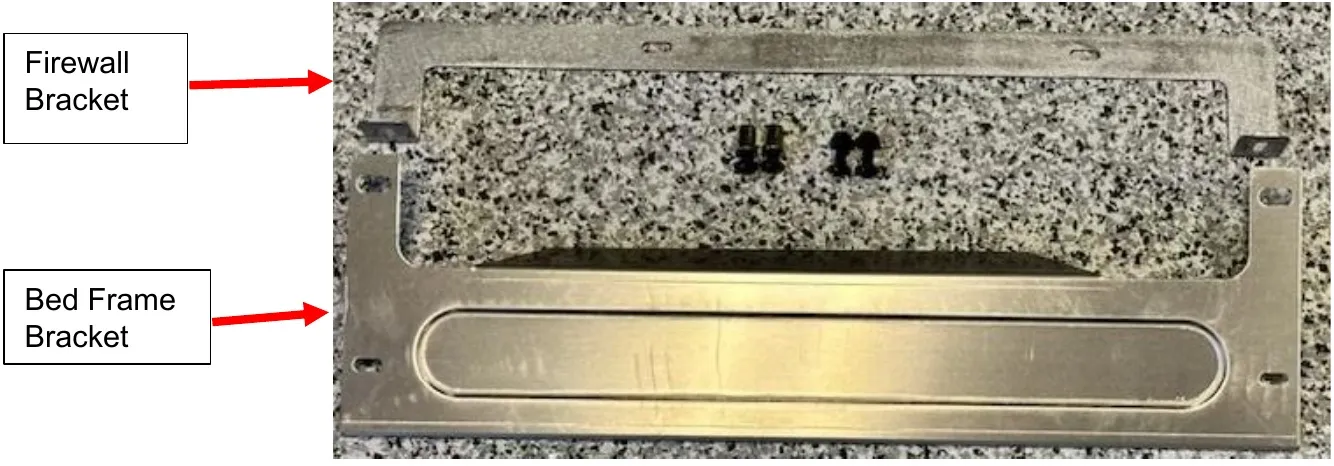
Locate firewall and bed frame brackets along with (4) M6x16mm flange bolts, (2) Nylock nuts and (2) M6 Nutzert.
- Step 2
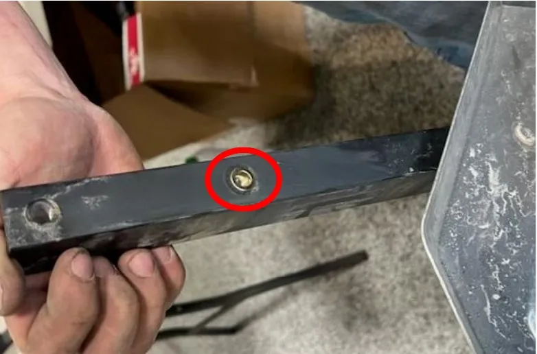
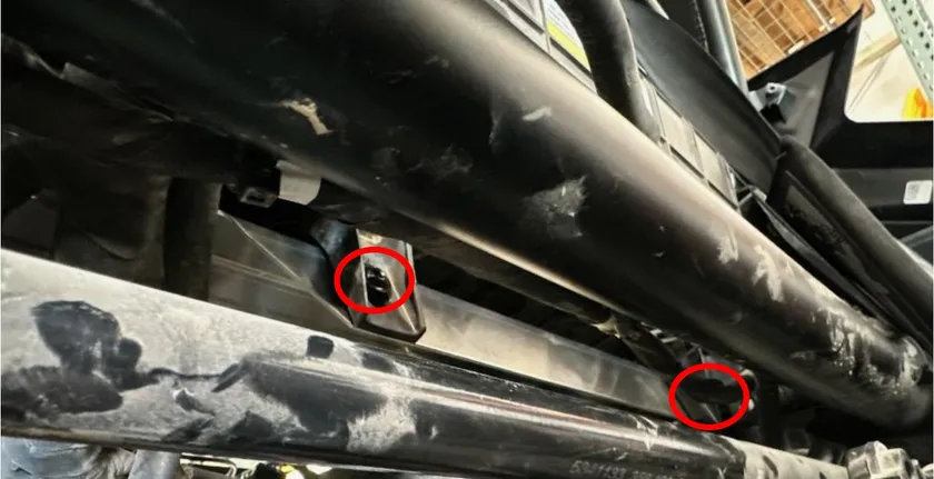
Locate the firewall side of the bed frame, you will find (4) holes total (2) per frame rail. Install a M6x1.0 Nutzert into the bottom hole. On the bottom of bed frame.
- Step 3
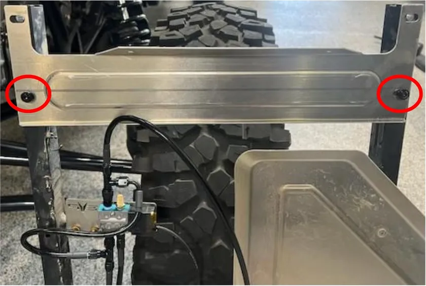
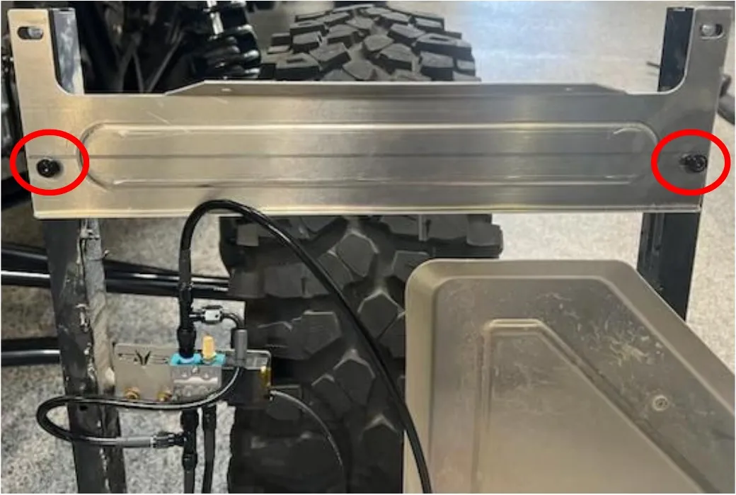
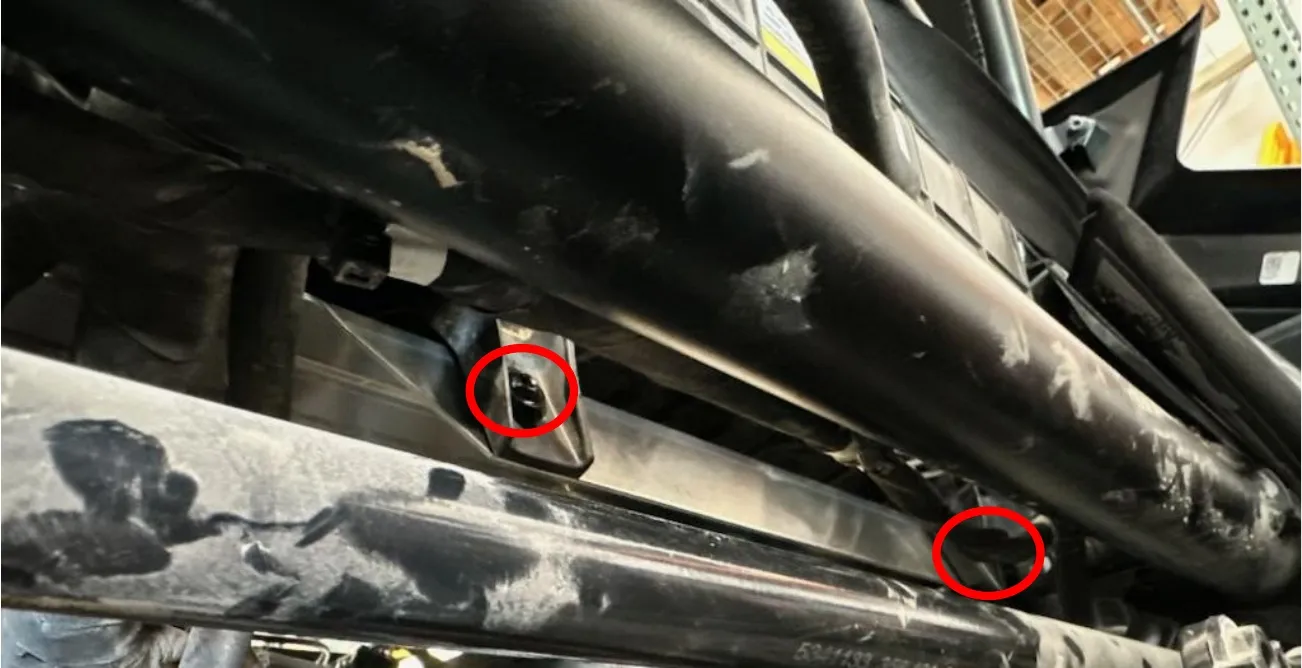
Install (2) M6x16mm flanged screws holding the bed frame air box relocation bracket to the bottom of the bed frame. See photo.
- Step 4
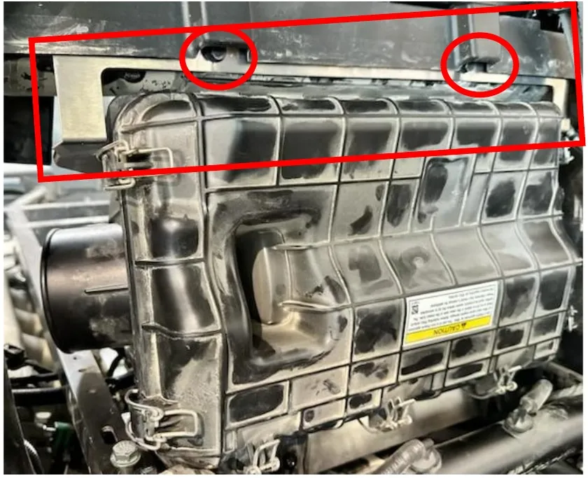
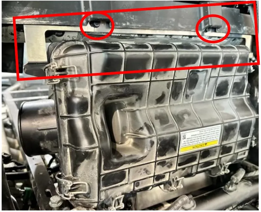
Install the bed frame loosely, flip the airbox 180 degrees (making sure the airbox still opens inside the cab). Install the firewall air box relocation bracket using OEM hardware.
- Step 5
Install (2) M6x16mm screws and (2) M6 Nylock nuts holding the bottom of the airbox to the bed frame air box relocation bracket.
- Step 6
Reinstall the bed frame with OEM hardware.
- Step 7
Reinstall airbox hardware and engine harness clips. Use supplied zip-ties.
- Step 8
Install supplied air filter and pre filter into the airbox.
Procedure
Pro R Boost Control
- Step 1
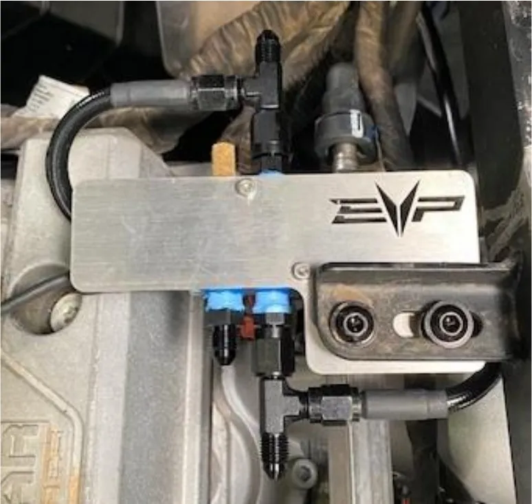
Locate the 4-Port boost control solenoid with bracket. Install the bracket onto the bed frame. Fasten down with (2) M6x16 flanged head screws. See below.
- Step 2
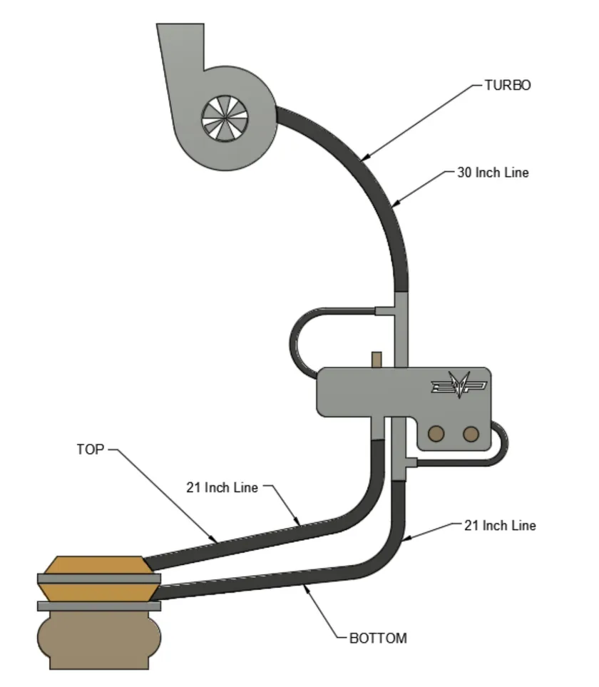
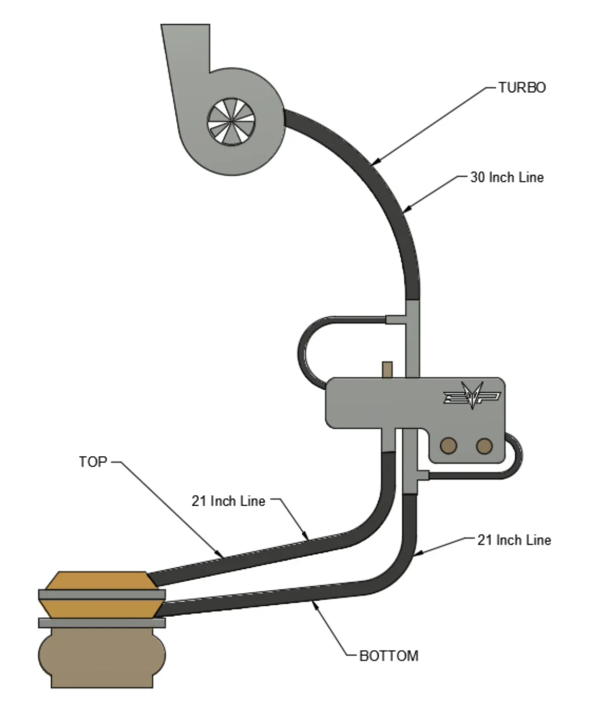
Install both 12” fire sleeve pieces onto the 21” lines. Install the 30” boost line between the top right “T” on the boost control solenoid to the turbocharger boost reference port. Install one 21” boost line between the bottom left single port on the boost control solenoid to the top port on the wastegate. Install the other 21” boost line between the bottom right “T” on the boost control solenoid to the bottom port on the wastegate. Fasten all fittings down with Teflon. (See diagram below).
Procedure
Pro R Kaizen Relay Harness (Pre 11-01-2025)
- Step 1
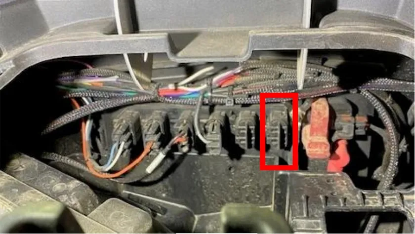
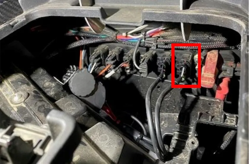
Locate the storage compartment on top of the dash. Remove the insert. With the insert removed you will find the electrical BUS bar. You will need (1) port. Remove (1) blank from the bus bar. Install (1) plug into the bus bar from the Kaizen relay harness.
- Step 2
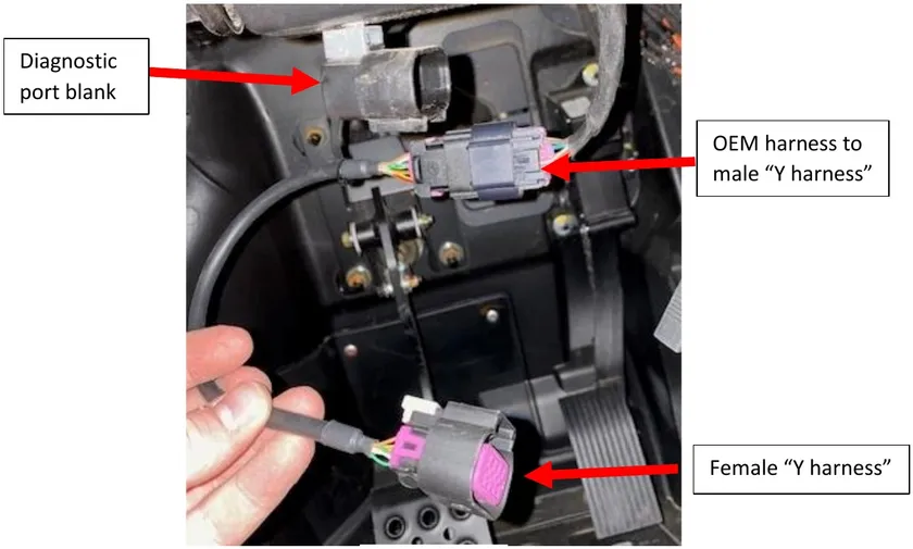
Run the diagnostic port “Y harness” under the dash and over to the diagnostic port located under the steering wheel. Remove the OEM diagnostic port from the blank and connect it to the male connector off the “Y harness”. Install the female end back into the blank.
- Step 3
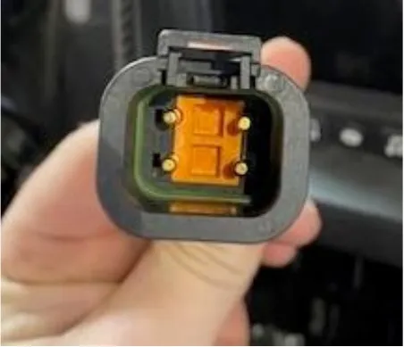
Route the 4-pin connector under the dash and through the center tunnel, by the shifter and cup holders. (If a 4-seater run it through the rear tunnel). Run the harness back to the firewall.
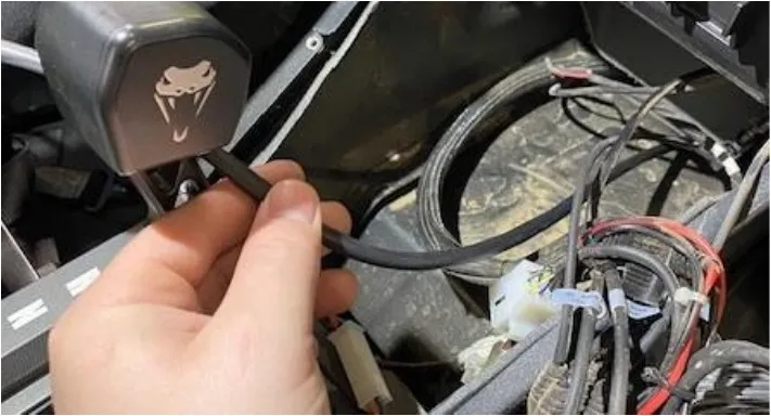
- Step 4
With the 4-pin connector back at the firewall, install the intercooler triple fan harness. Run the triple fan harness back to the intercooler fans (on the inside of the cage). Also attached to the triple fan harness is a 2-pin connector. Connect the 2-pin connector to the 4-port boost control solenoid.
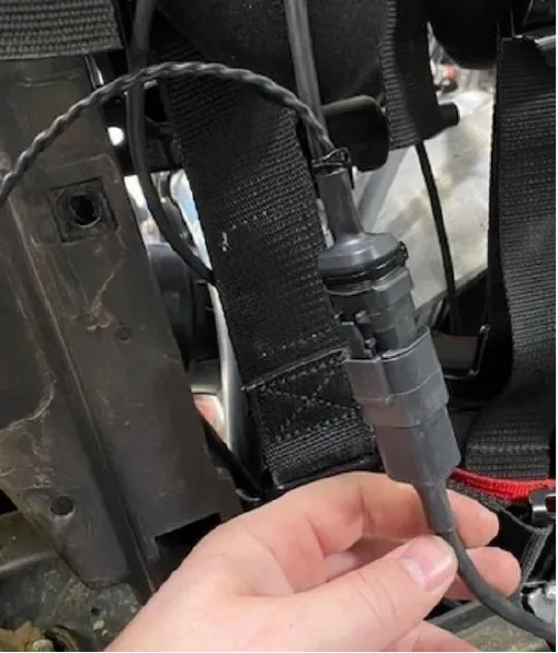
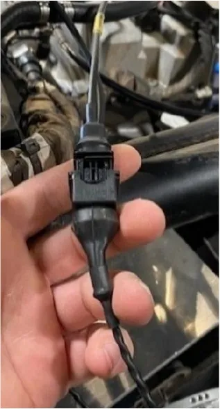
- Step 5
Use (2) supplied 5/16” P-clamps to secure the (3) fan harnesses to the intercooler cage. Remove a M6 screw to fasten the clamp down with.
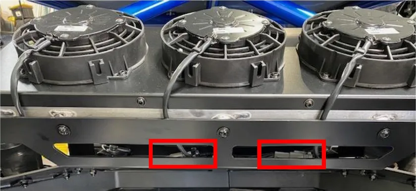
- Step 6
Use supplied zip-ties to secure all wire harness to the frame, up to the front compartment.
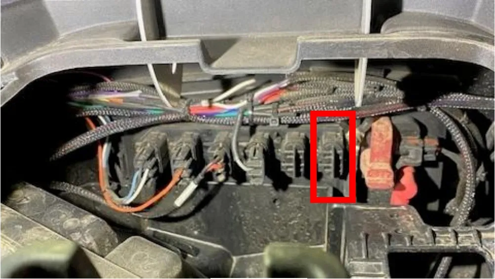
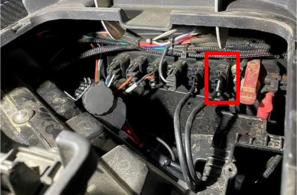
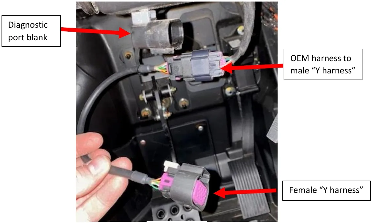
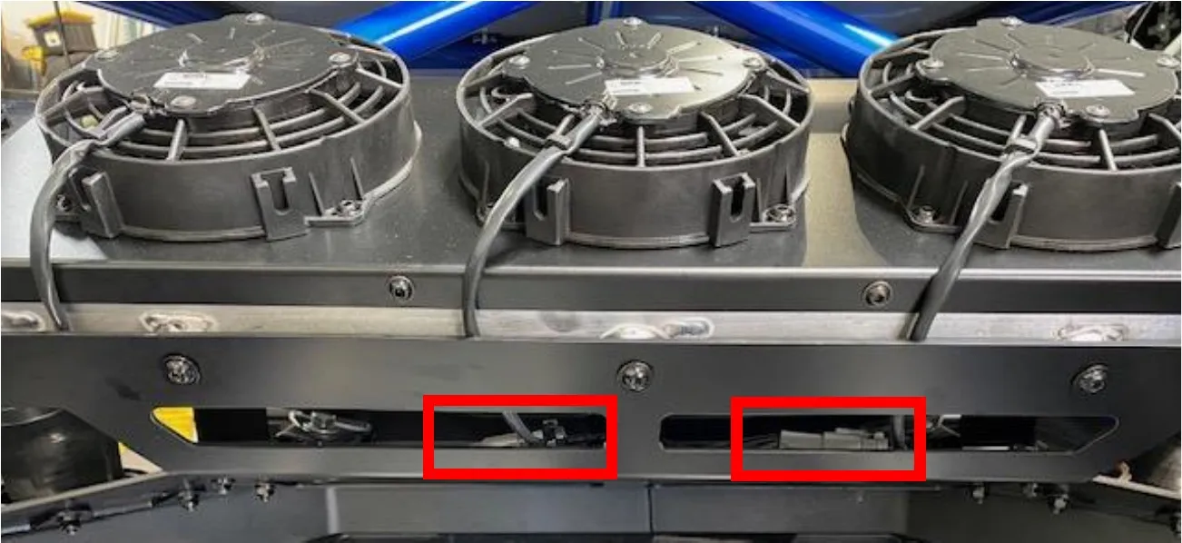
Note
While keyed off, the CAN module LED should be solid RED. When fully keyed on (engine running or not), the CAN module LED should be flashing GREEN.
Note
If upgrading from a 330 kit, make sure your intercooler fans are re-pinned. Blue (positive) position 2. Black (ground) position 1.
Procedure
Pro R Boost Control Harness (Post 11-01-2025)
- Step 1
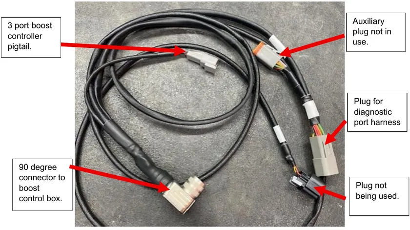
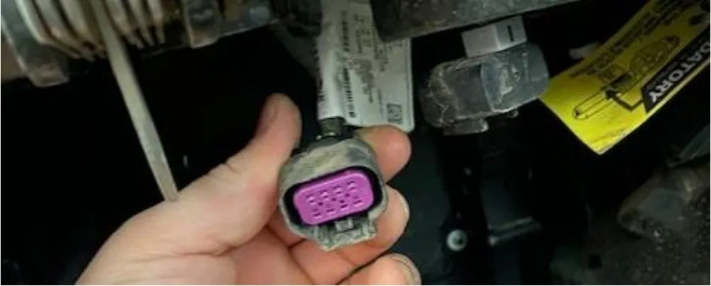
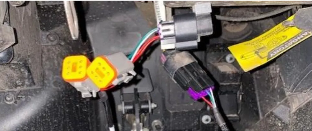
Locate the diagnostic port plug, remove it from the blank. Plug in the supplied Polaris diagnostic port replicator.
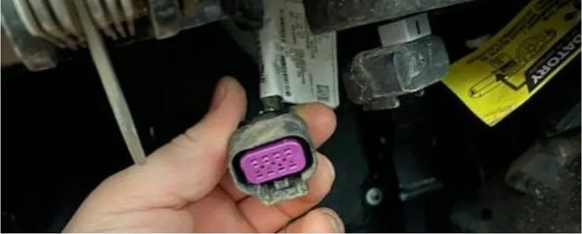
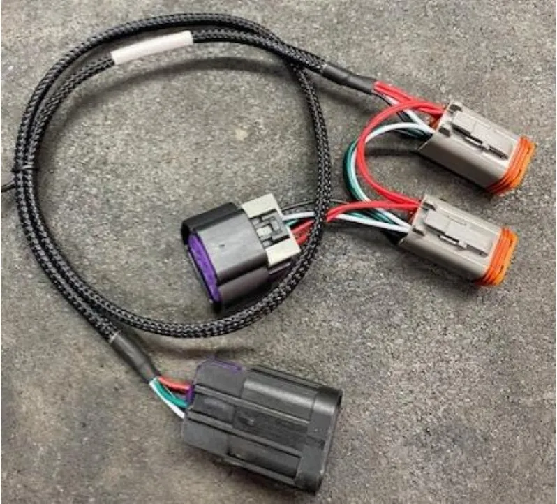
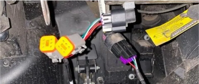
- Step 2
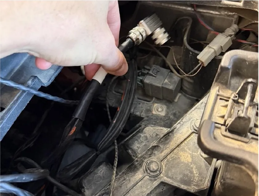
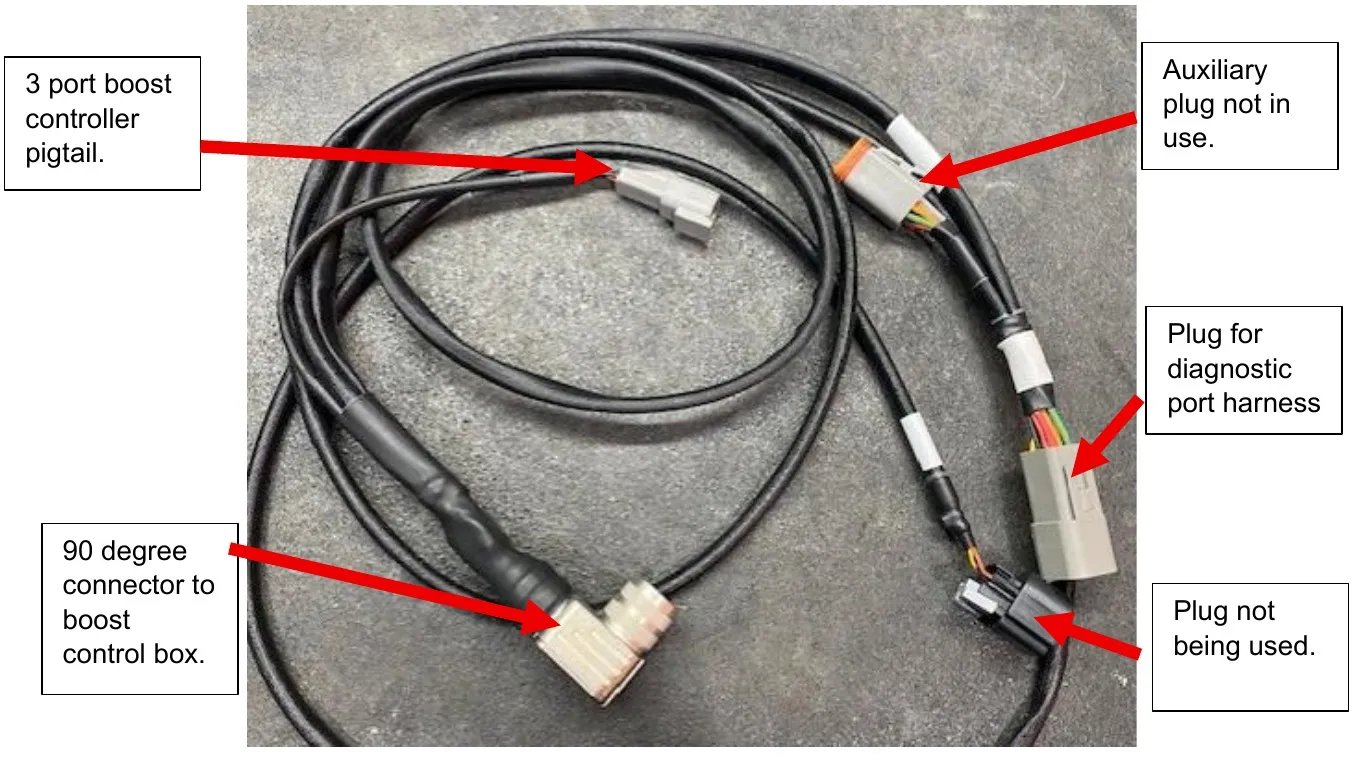
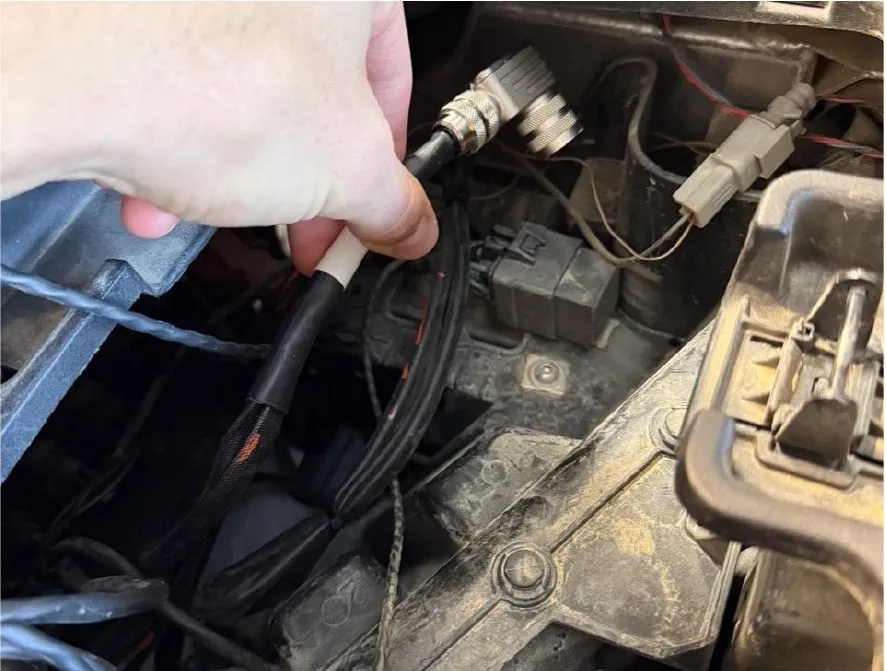
Open the center dash, remove the inside bin. Route the boost control 90 degree fitting up through the dash.
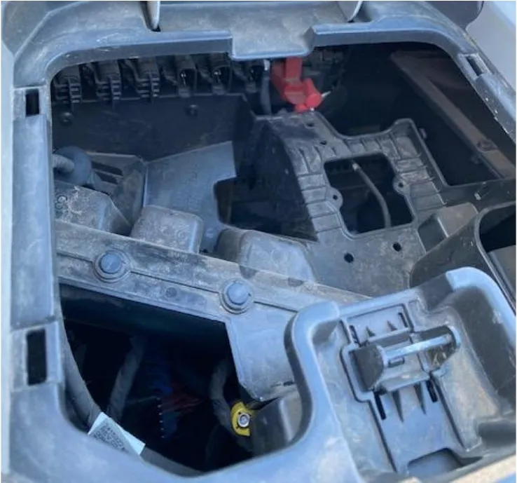
- Step 3
Clean an area under the glove box very well. Pick a spot that will allow the inside bin to sit flush. Install Velcro onto the back side of the black box. Install the black box under the dash. Connect the 90-degree plug to the black box. DON’T OVER TIGHTEN.
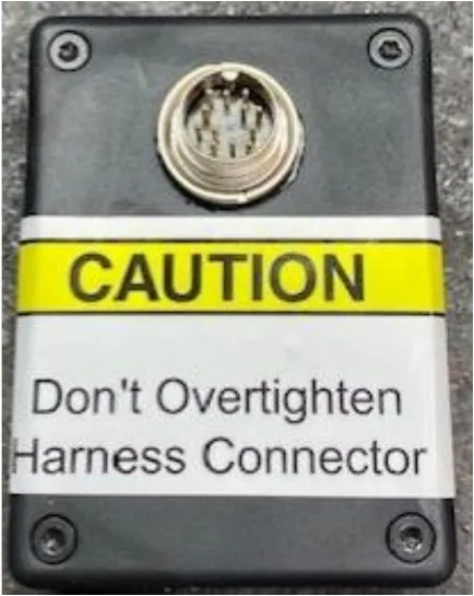
CAUTION Don't Overtighten Harness Connector 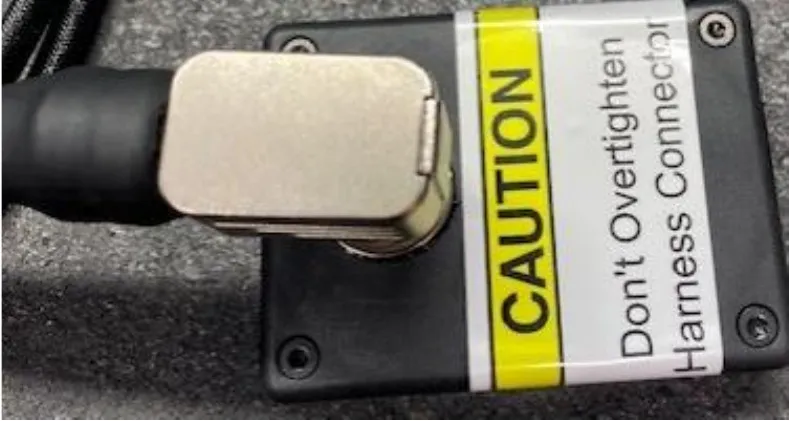
CAUTION Don't Overtighten Harness Connector - Step 4
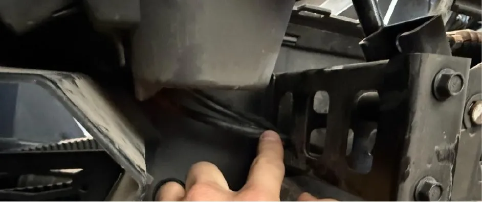
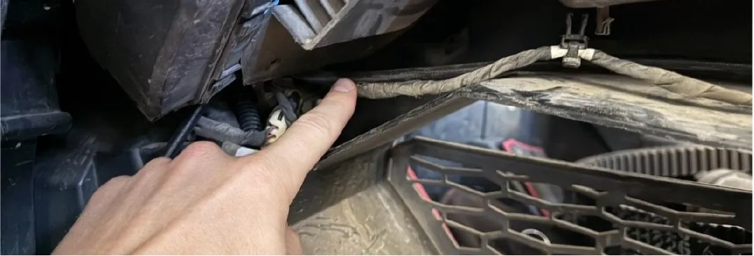
Route the 2-pin boost control connector under the dash, through the center tunnel.
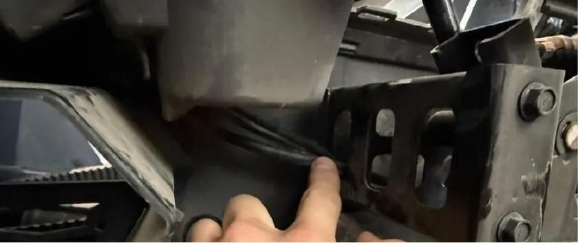
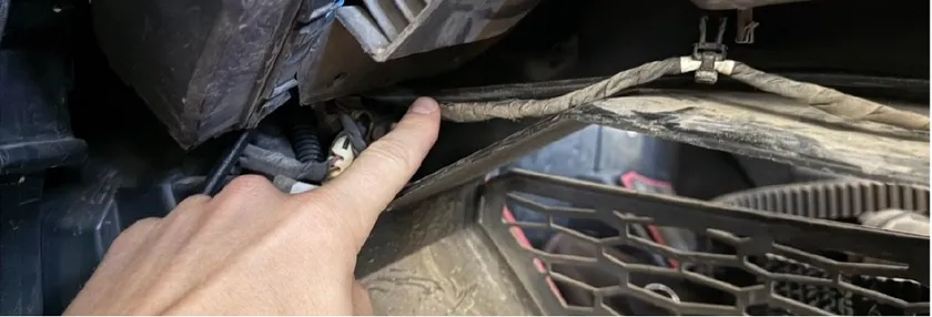
- Step 5
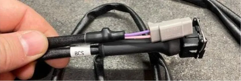
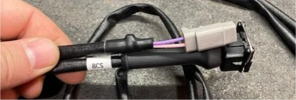
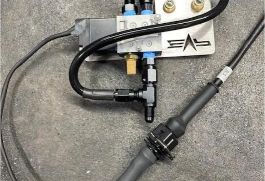
Connect the second boost control harness into the 2pin connector. Route the black 2-pin connector back to the boost solenoid. Keep away from heat sources.
- Step 6
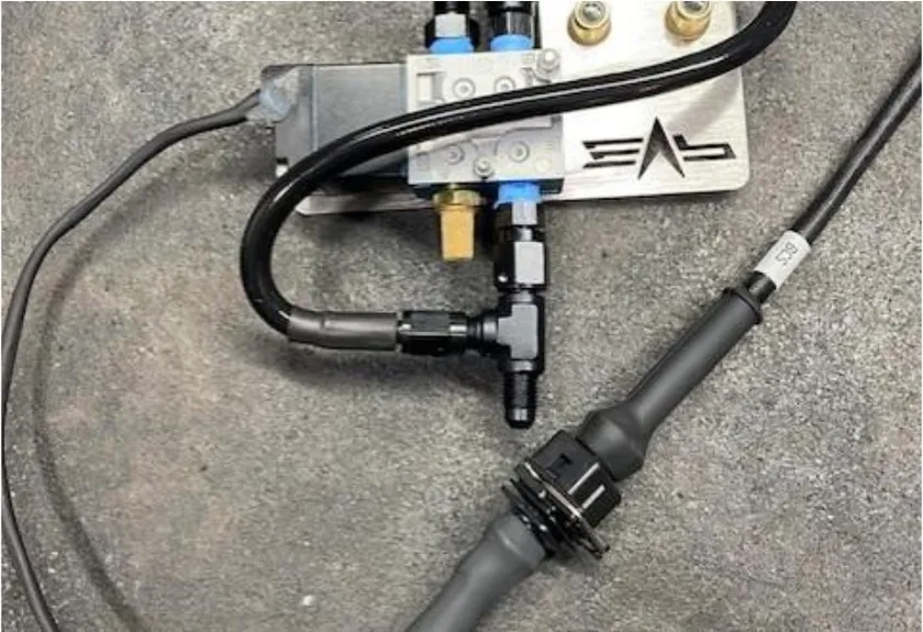
Connect the boost control harness into the boost control solenoid.
Procedure
Pro R Catch Can
- Step 1
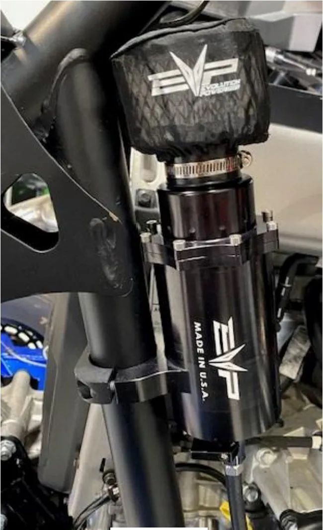
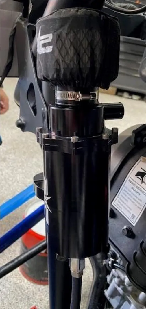
Install the catch can on the right-rear frame. Tighten down the clamp around the tube frame. The port on the cap will face the engine bay. Install the 1/4" rubber hose to the barb located on the bottom of the catch can. Run it down into the belly pan.
- Step 2
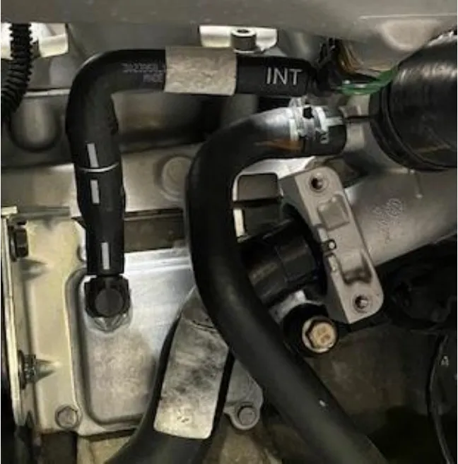
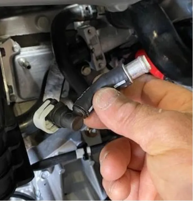
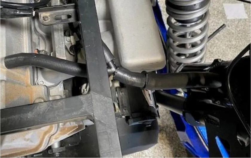
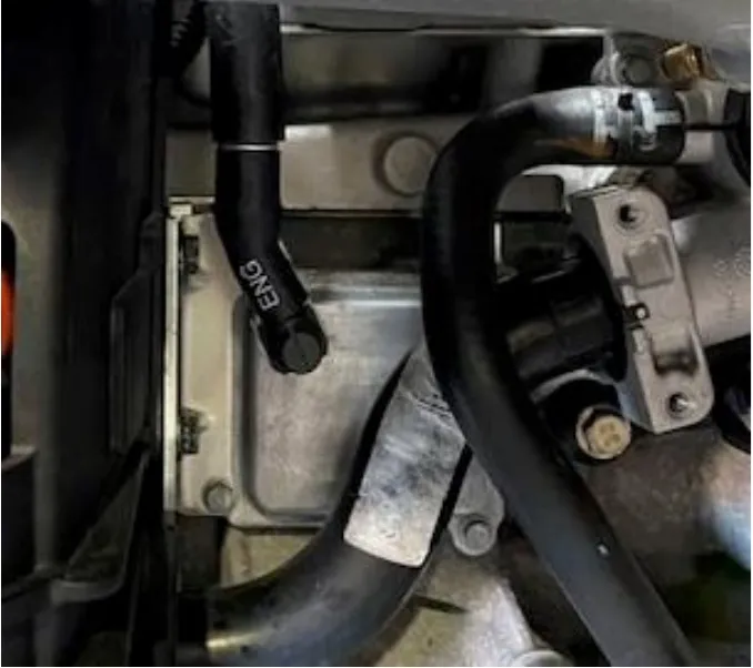
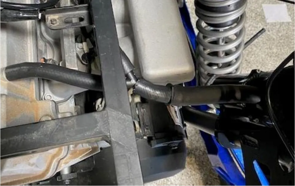
Locate the engine breather hose going to the plenum (which is currently removed). Remove the hose from the engine. Remove the longer piece of hose. Keep the small piece with the connector and one-way-ball valve. Reconnect the small piece to the engine.
- Step 3
Install the catch can hose. The “Y” portion of the hose will go to the small connector on the engine and the valve cover.

Procedure
Pro R Blow Off Valve (BOV)
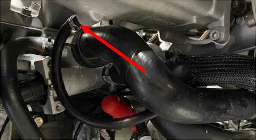
- Step 1
Install the pre-filter onto the BOV and use supplied zip-tie around the base of the BOV to hold the prefilter on.
- Step 2
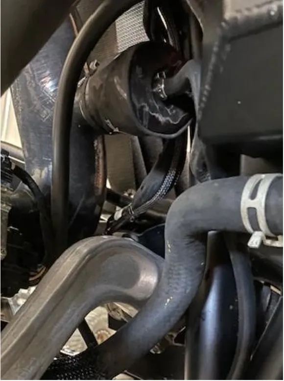
Install the BOV into the charge tube between the intercooler and throttle body. Use supplied 25-40mm worm drive to fasten down.
- Step 3
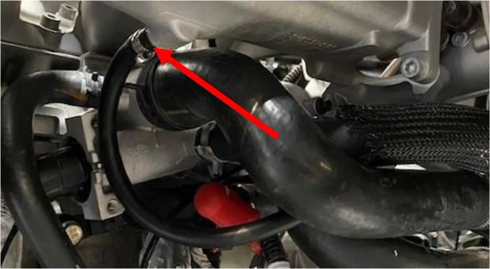
Install the vacuum line to the BOV and plenum barb, that was installed earlier. Use pinch clamps to secure.
- Step 4
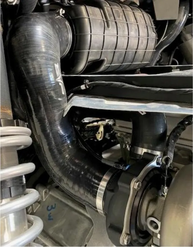
Install the V-flow from the turbocharger to airbox. Use supplied 70-90mm and 90-110 worm drive clamps.
Procedure
Pro R Turbocharger Exhaust
- Step 1
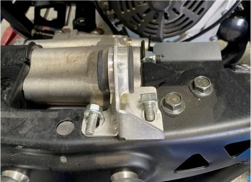
Remove the lower exhaust isolator from the frame. Use a 13mm socket.
- Step 2
Install the exhaust clamp onto the muffler pipe. Install the muffler to the vehicle, re-use both top isolators. Install the bottom isolator onto the muffler and frame. Reinstall hardware.
- Step 3
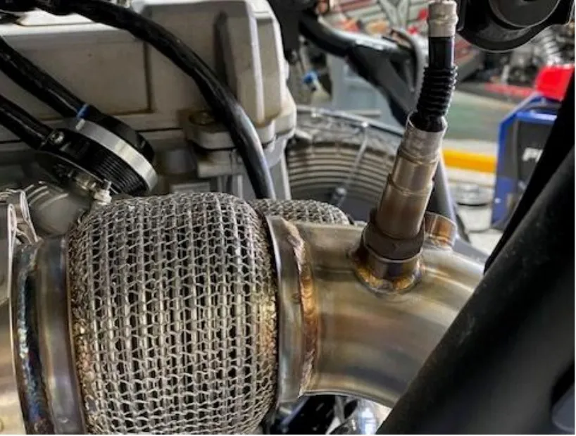
Remove the 02 sensor out of the OEM header using a 7/8” or 19mm wrench. Use anti seize on the threads and install onto the new down pipe. Reconnect the electrical connector to the harness.
- Step 4
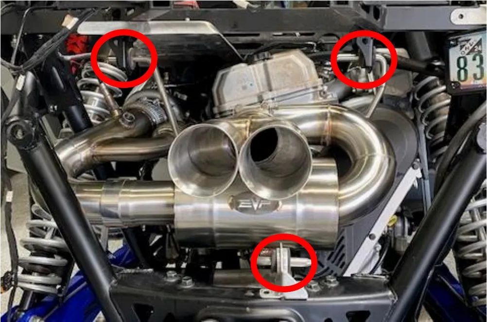
Tighten all clamps on the turbocharger, wastegate, mid-pipe, muffler, and muffler tips. Use anti seize on all threads. DO NOT overtighten the V-band clamps.
Procedure
Polaris Pro R Rear Facia
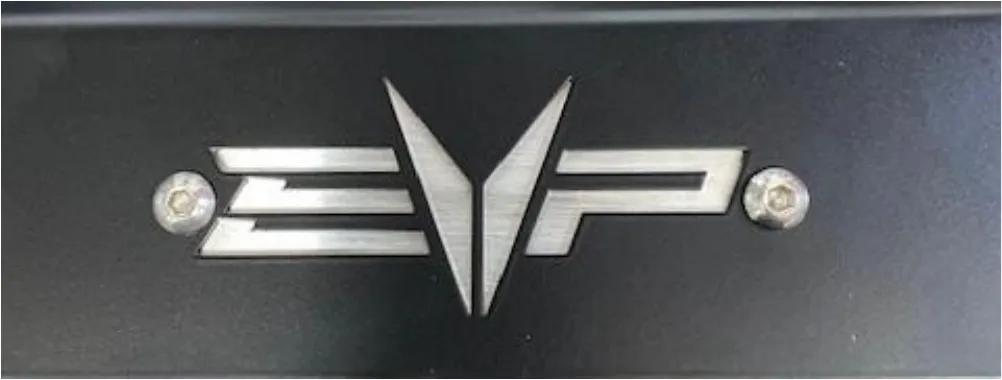
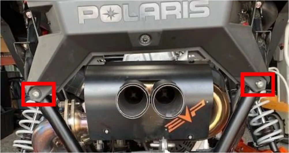
- Step 1
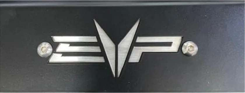
Open the new Pro R rear Facia box. Place the raw aluminum backer plate onto the rear facia trim. Use the M4 hardware and install. Keep the head of the screws on the outside.
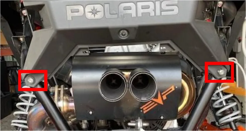
- Step 2
With a T50 socket remove the (2) screws holding the rear facia to the frame. Keep the plastic step washers.
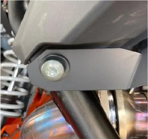
- Step 3
Place the EVP facia trim piece onto the vehicle. Reuse the OEM plastic step washer and bolt. Start securing but leave somewhat loose.
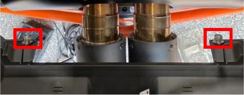
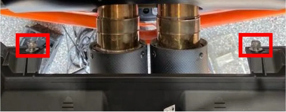
- Step 4
Install the remaining hardware through the OEM plastic tabs. Place a washer on the head and nut side. Fasten down. Also finish fastening the T50 screws.
Procedure
Pro R Paragon Fuel Pump Assembly Upgrade
- Step 1
Remove the (4) bed screws using a T-40. Remove the bed.
- Step 2
Remove the passenger and driver seat, if a 4-seater remove the rear seats.
- Step 3
Remove both firewall panels, (6) 1/4-turn fasteners.
- Step 4
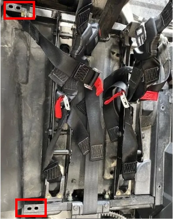
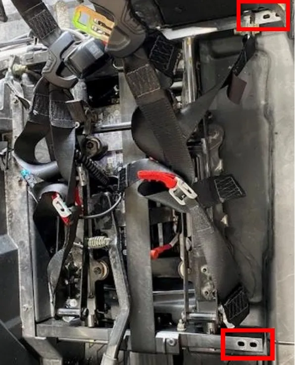
Remove (8) 13mm bolts holding the seat frame in place. (2) on each corner.
- Step 5
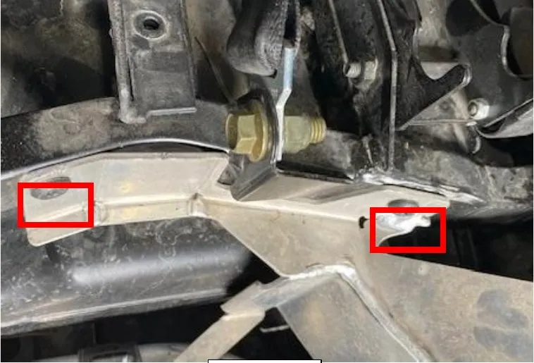
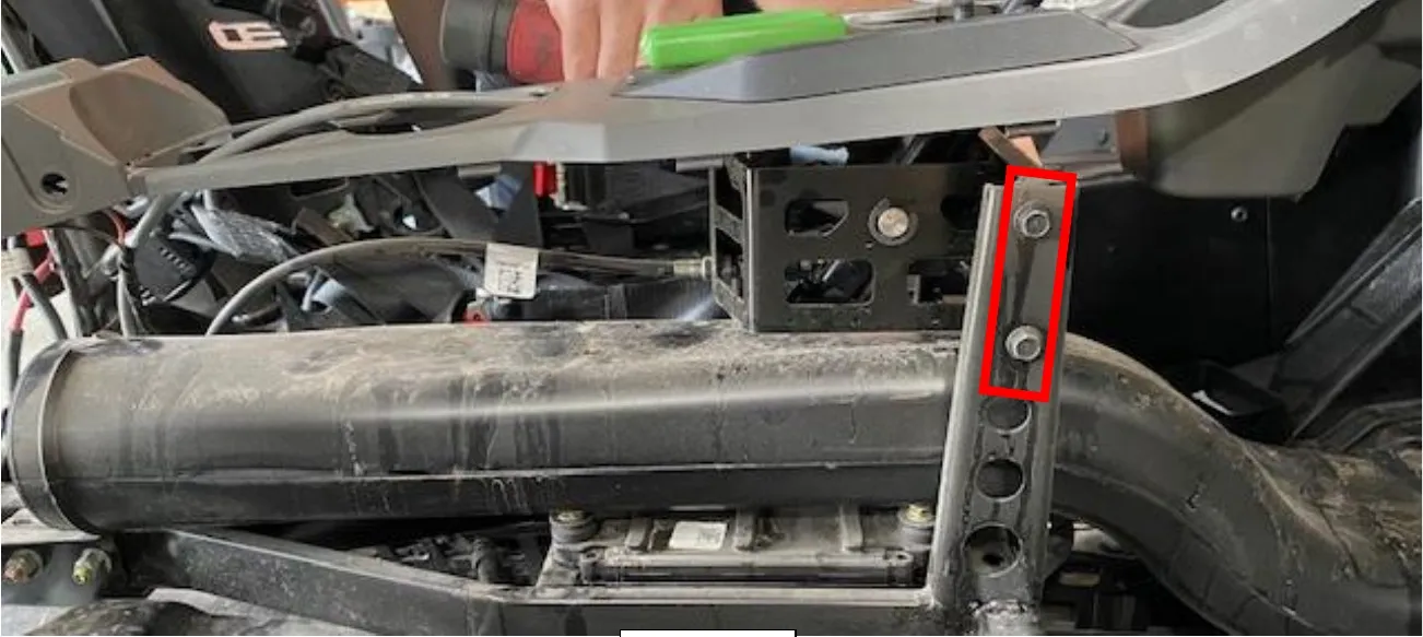
Remove the belt deflection plate from the frame. (2) T40 screws and (1) coolant line bracket.
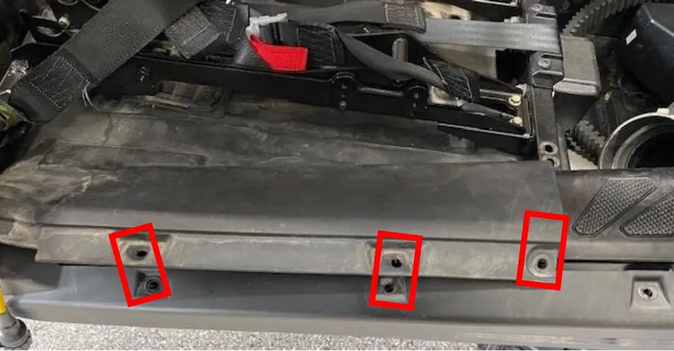
- Step 6
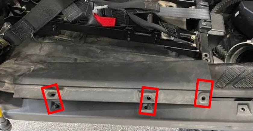
On the passenger side, remove (3) T-40 screws holding the kickplate and interior plate together.
- Step 7
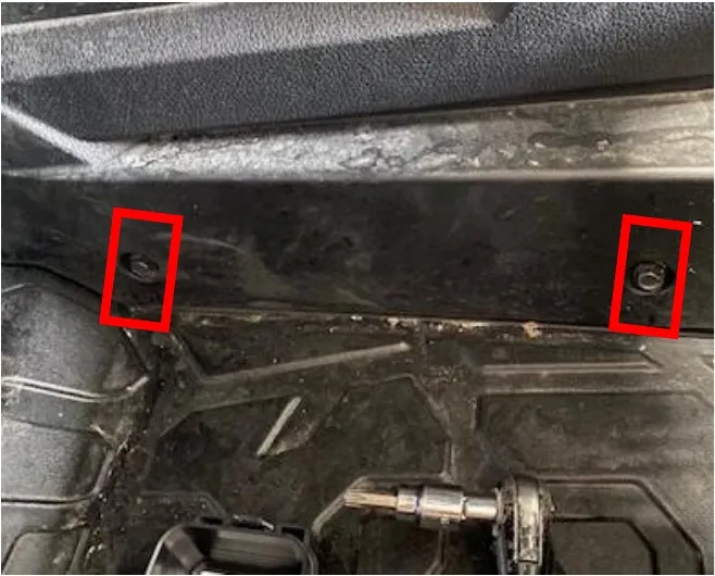
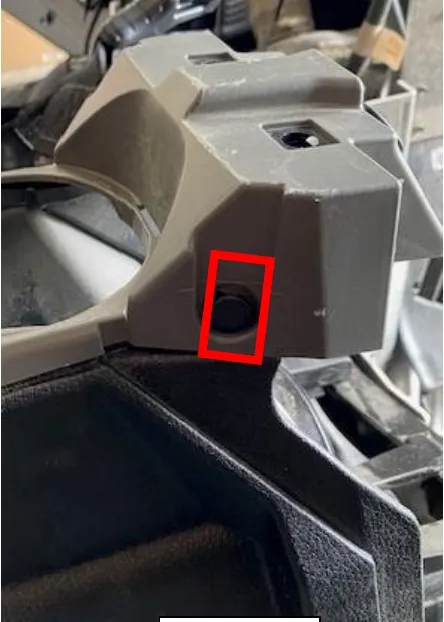
Remove (8) 10mm on each side of the center tunnel. (2) push darts on the rear and (2) push darts up underneath the dash.
 Note
Unplug the 12v power supply and footwell lights.
- Step 8
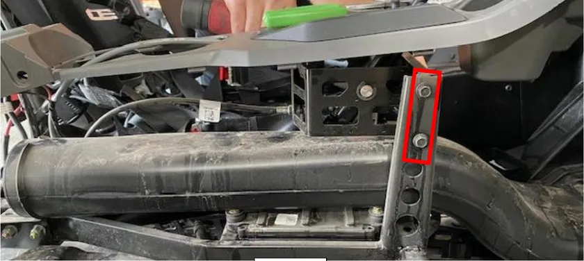
Pop the top grey center piece up, this will make both sides free. Remove both sides. With a 10mm socket remove (6) screws holding the shifter to the frame.
- Step 9
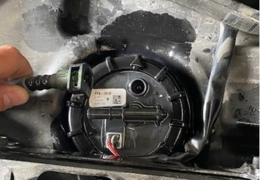
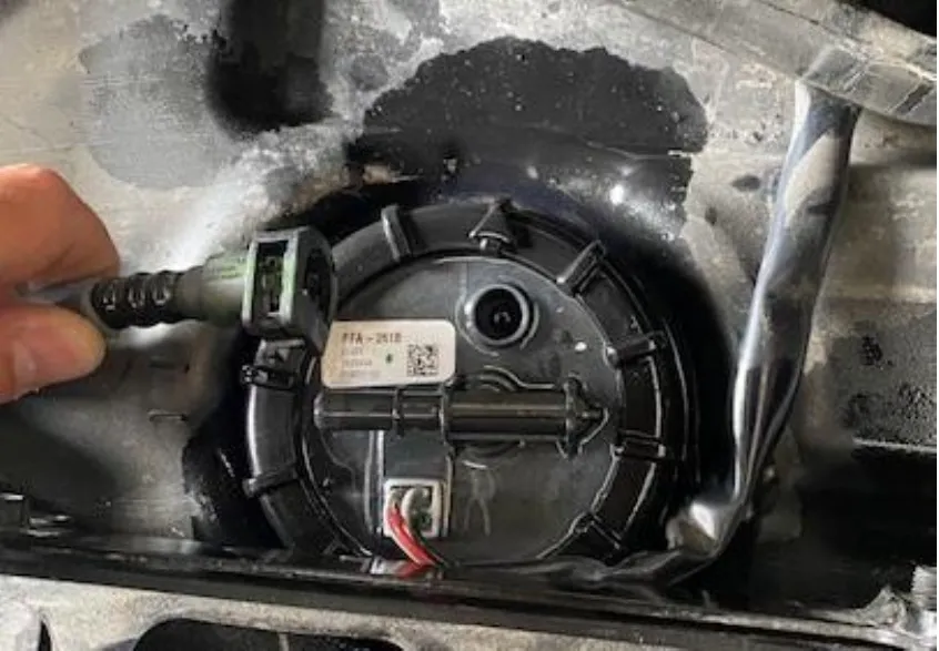
Now you can lift the frame about 8.0”, remove the interior plate and access the fuel pump assembly. Disconnect the fuel hose and wiring harness. Use EVP Fuel Pump Tool to remove the nut.
 Note
Fuel will pour out of the OEM surge tank with removal.
- Step 10
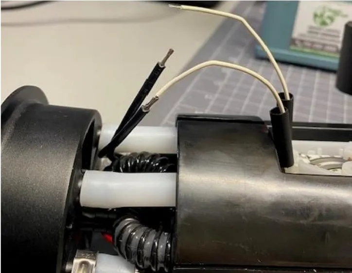
Cut and remove the float from the OEM assembly. Install it onto the new assembly and solider the wires together. Orientation does NOT matter.
- Step 11
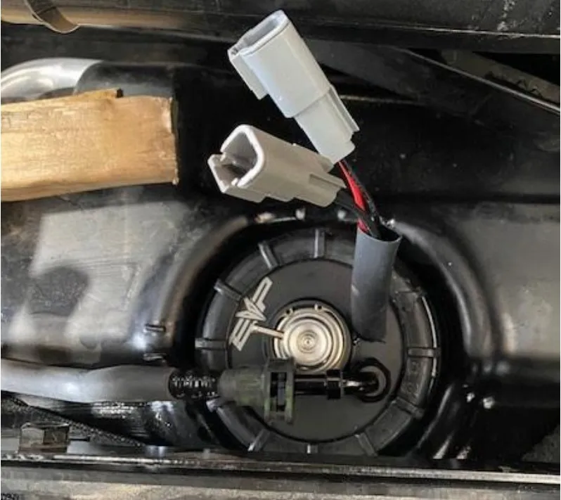
Drain your fuel tank now if your changing fuels. Install the new fuel pump assembly, making sure orientation is correct and the fuel hose isn’t in contact with anything. Reuse the OEM sealing ring.
- Step 12
Locate the interior plastic and cut on the silver line. This will allow your interior to be reused and not interfere with the new fuel pump assembly.
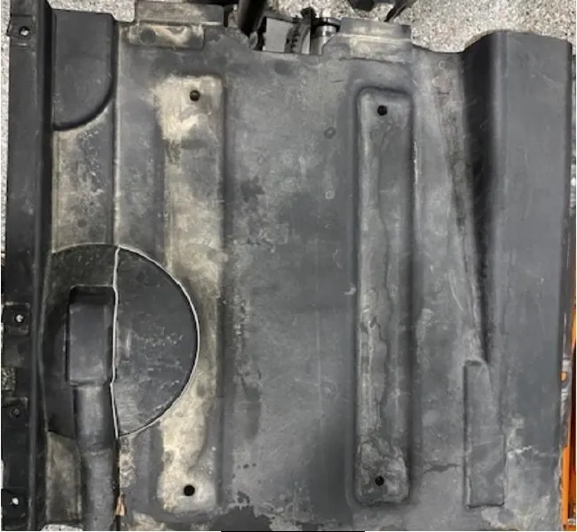
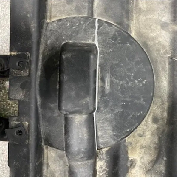
- Step 13
Reinstall the interior plastic piece. Make sure everything is clear.
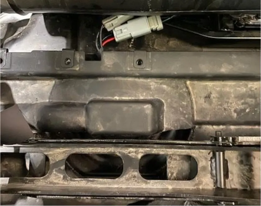
- Step 14
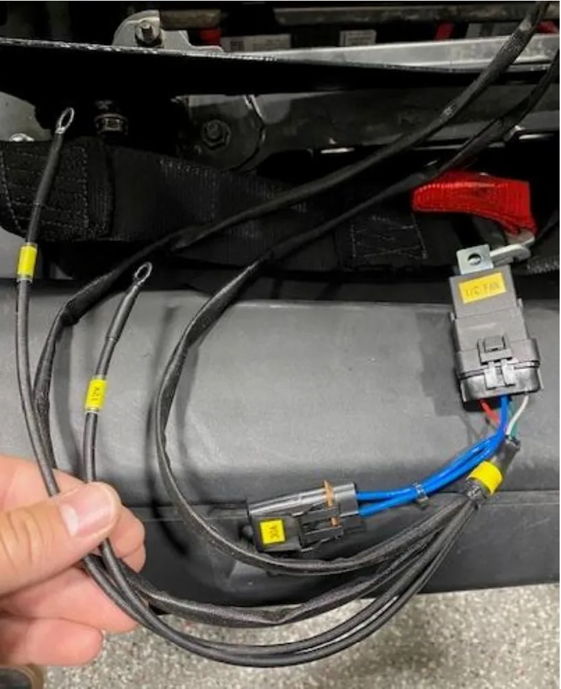
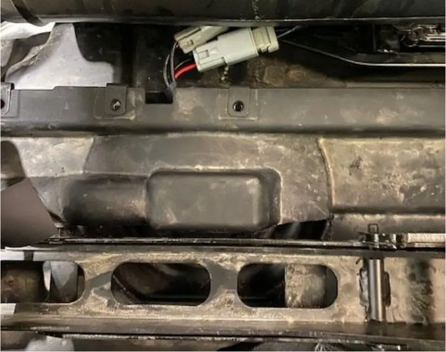
Connect the Polaris fuel pump harness to the vehicle. Power and ground to the battery, mount the relay to a stud, plug into the OEM fuel pump connector, plug into the fuel pump and float coming out of the billet hat.
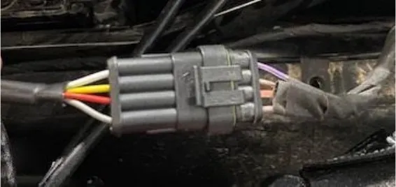
Note
If using rising rate setup (700 Kit ONLY), connect the vacuum line from the fuel pressure regulator to the throttle body port. If running the 500 kit, DO NOT hook up rising rate.
- Step 15
Reinstall the frame, interior, center tunnel, firewall and seats in reverse order.
Procedure
Pro R Turbocharger Clutching
- Step 1
Remove the (5) CVT cover bolts using a 10mm socket. Loosen the 1/4 twist latches around the CVT cover. Remove the cover.
- Step 2
Remove the belt.
- Step 3
Remove the primary bolt using a breaker bar and T60 socket.
- Step 4
Use a P90X primary clutch puller to remove the primary clutch from the crankshaft.
- Step 5
Remove the secondary bolt using a 13mm socket.
- Step 6
Using a clutch compression tool, loosen (3) helix bolts using a 13mm socket.
- Step 7
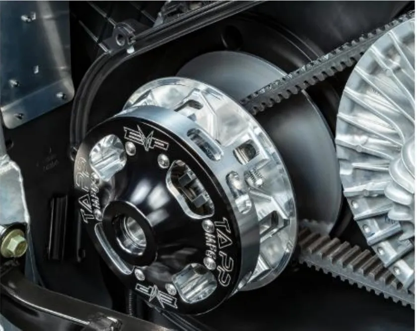
Remove the OEM secondary spring and install supplied orange/blue spring. Put the secondary clutch back together.
- Step 8
Reinstall the secondary clutch and torque the bolt to 55 ft-lbs.
- Step 9
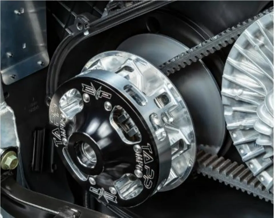
Install the TAPP primary clutch. Install supplied spacer on the OEM bolt and torque to 90 ft-lbs.
- Step 10
Reinstall the CVT belt in the correct orientation.
- Step 11
Spin the secondary a total of 5 rotations to set belt deflection.
- Step 12
Reinstall the CVT cover and hardware.
Procedure
Finishing Up
- Step 1
Change engine oil and oil filter.
- Step 2
Add coolant to the reservoir.
- Step 3
Drain the fuel tank and add correct fuel for your tune.
- Step 4
Reinstall your ECU.
- Step 5
Start the vehicle and let it idle for a few minutes, keep an eye on the coolant level. Add if necessary. Look for any leaking. Once the coolant level is correct, shut the vehicle off.
- Step 6
Reinstall all body panels, bed, skid plate, interior, etc.
Emissions notice. This product is exempt from the emission standards and related requirements of 40 C.F.R. § 1051 as provided by 40 C.F.R. § 1051.620, and California law [e.g., vehicle code §§ 27156 and 38391]. This product is sold only for use in connection with EPA certified, purpose-built, nonroad vehicles used solely for closed course, nonroad competition/racing and not used for any recreational purpose or on public highways or right of ways maintained by and open to the public. This product is sold only in connection with machines that do not fall under state and/or federal noise or emission standards/regulations. Purchasers who/that purchase this product represent and warrant that the product is purchased only in connection with EPA-certified, emission-regulations-exempt and noise-regulations-exempt competition/racing vehicles as interpreted under applicable state and/or federal law.
Need technical support?
Submit a ticket with your vehicle and what you're seeing, and our support team will get back to you.
