 BUY NOW, PAY LATER. Starting at 0% APR


Polaris Pro R EVP 12mm Head-Studs
Pro R EVP 12mm Head-Studs
In the box
Parts and tools
Included parts
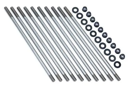
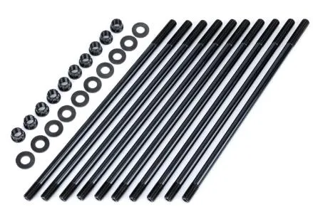
- 10Head Studs
- 10Nuts
- 10Washers
- 1Assembly Lube
Procedure
Installation
- Step 1
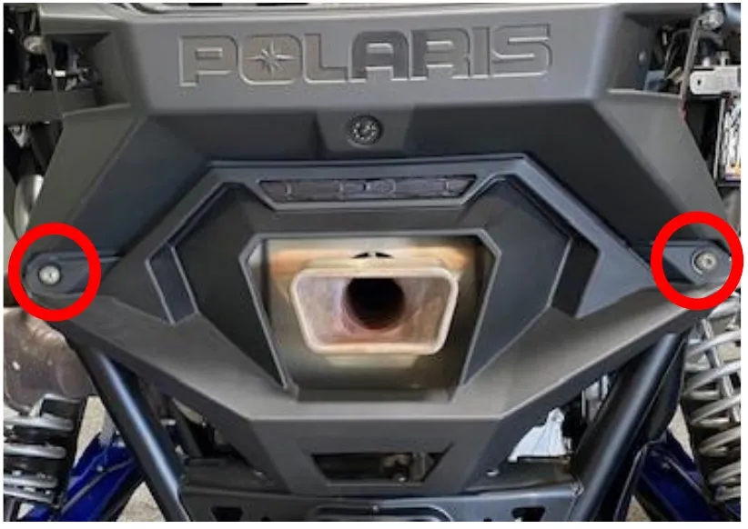
Remove the bed, bed frame, unplug taillights and camera, lower/upper rear valance, muffler tips, muffler, etc.
- Step 2
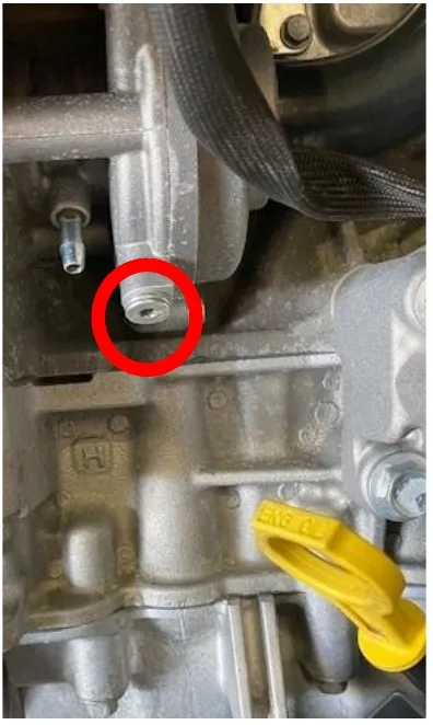
Remove the coolant reservoir cap. Locate the water pump housing (above the oil filter) and remove the 4mm Allen plug. Place a catch pan underneath the vehicle.
- Step 3
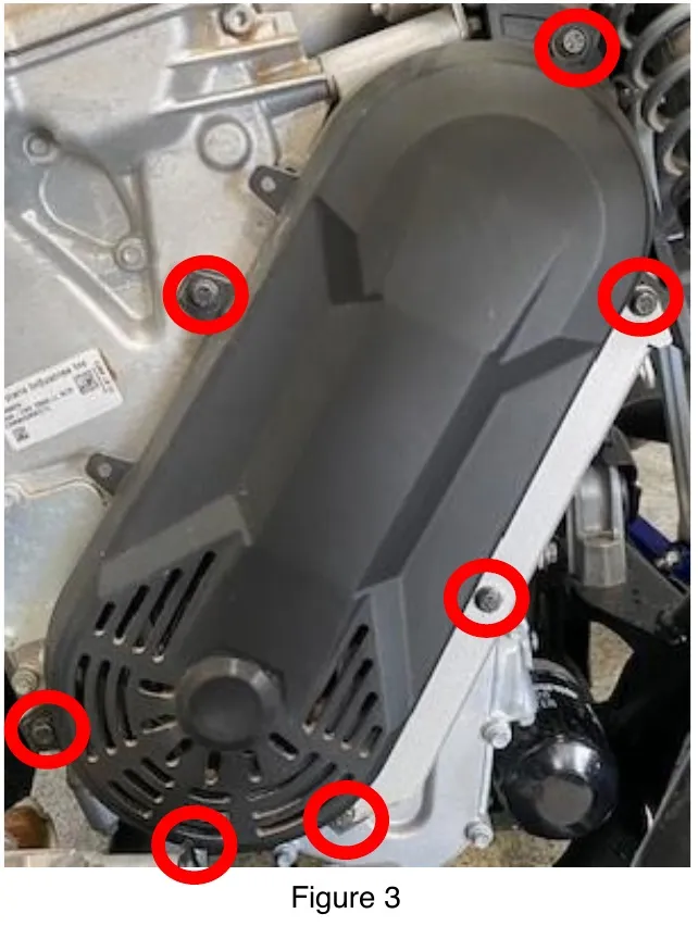
Remove the alternator belt cover. (7) 10mm screws.
- Step 4
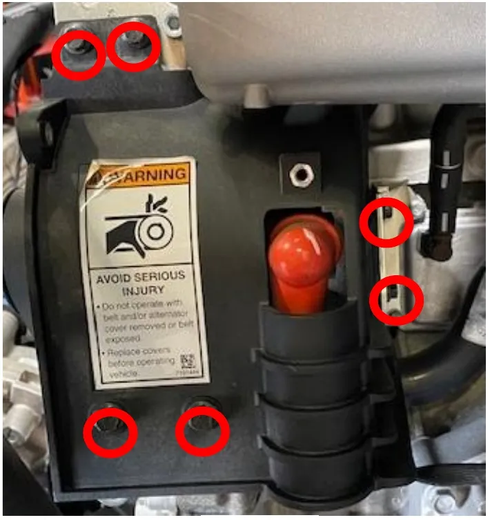
Remove the alternator shroud. (6) 10mm screws.
- Step 5
Remove the alternator stretch belt. Use a 19mm socket to turn the crank.
- Step 6
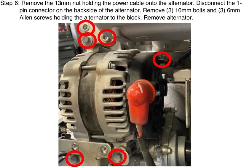
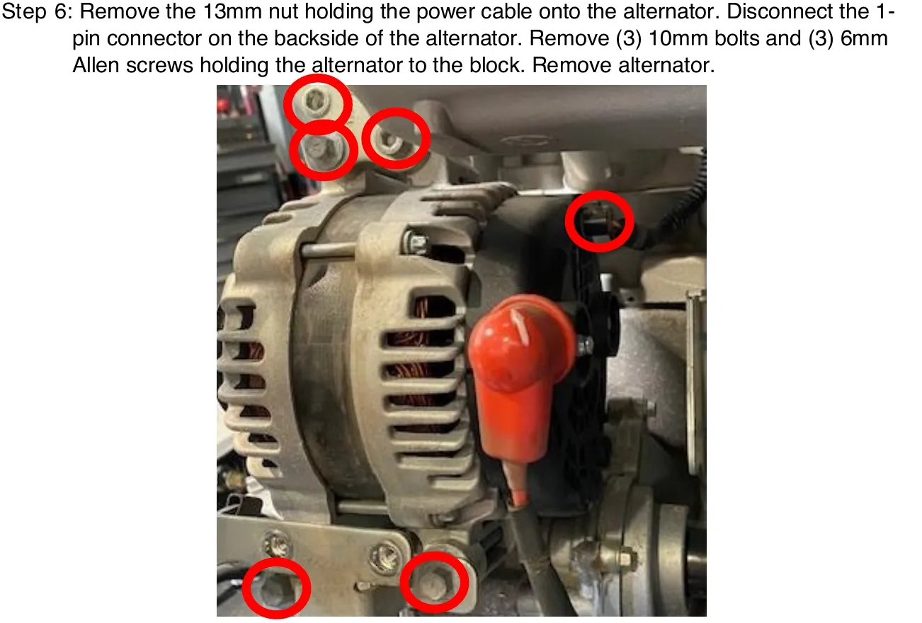
Remove the 13mm nut holding the power cable onto the alternator. Disconnect the 1-pin connector on the backside of the alternator. Remove (3) 10mm bolts and (3) 6mm Allen screws holding the alternator to the block. Remove alternator.
- Step 7
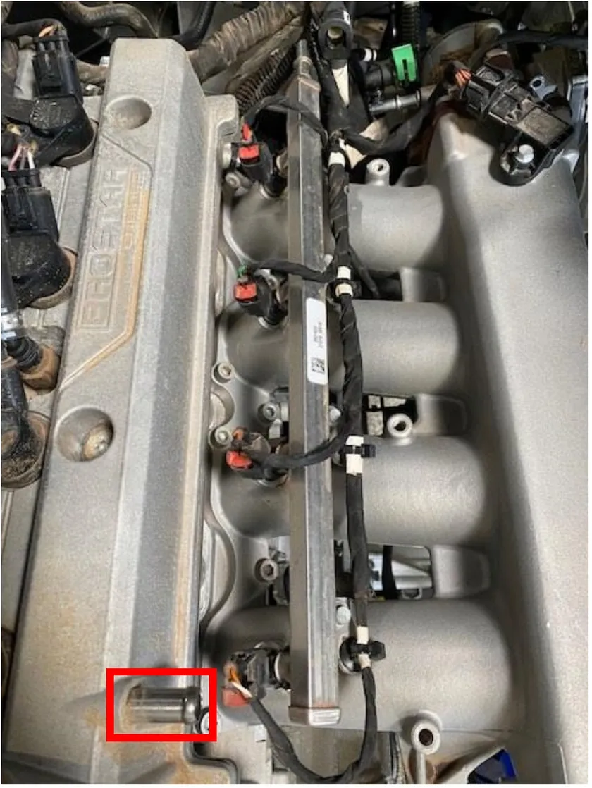
Remove the valve cover breather tube. Disconnect the coolant temperature sensor underneath the plenum. Located between cylinder 3 & 4.
 Caution
clean the entire engine and valve cover with compressed air if you haven’t already!
- Step 8
Remove the (4) ignition coils using a 8mm & 10mm socket.
- Step 9
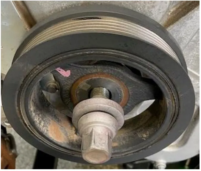
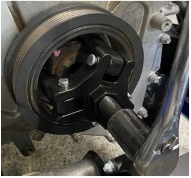
Remove the harmonic damper bolt, using a 19mm socket.
 Note
Use a Damper Puller OTC PN: 6667 to remove the damper.
- Step 10
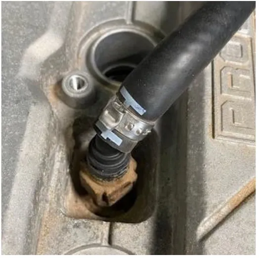
Remove the coolant line quick connector from the valve cover.
- Step 11
Remove the (8) valve cover screws using a T-40 socket. Remove the valve cover and rubber gasket.
- Step 12
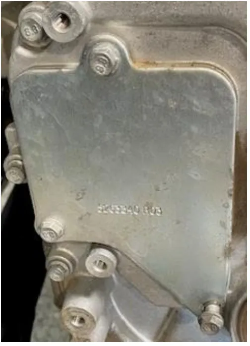
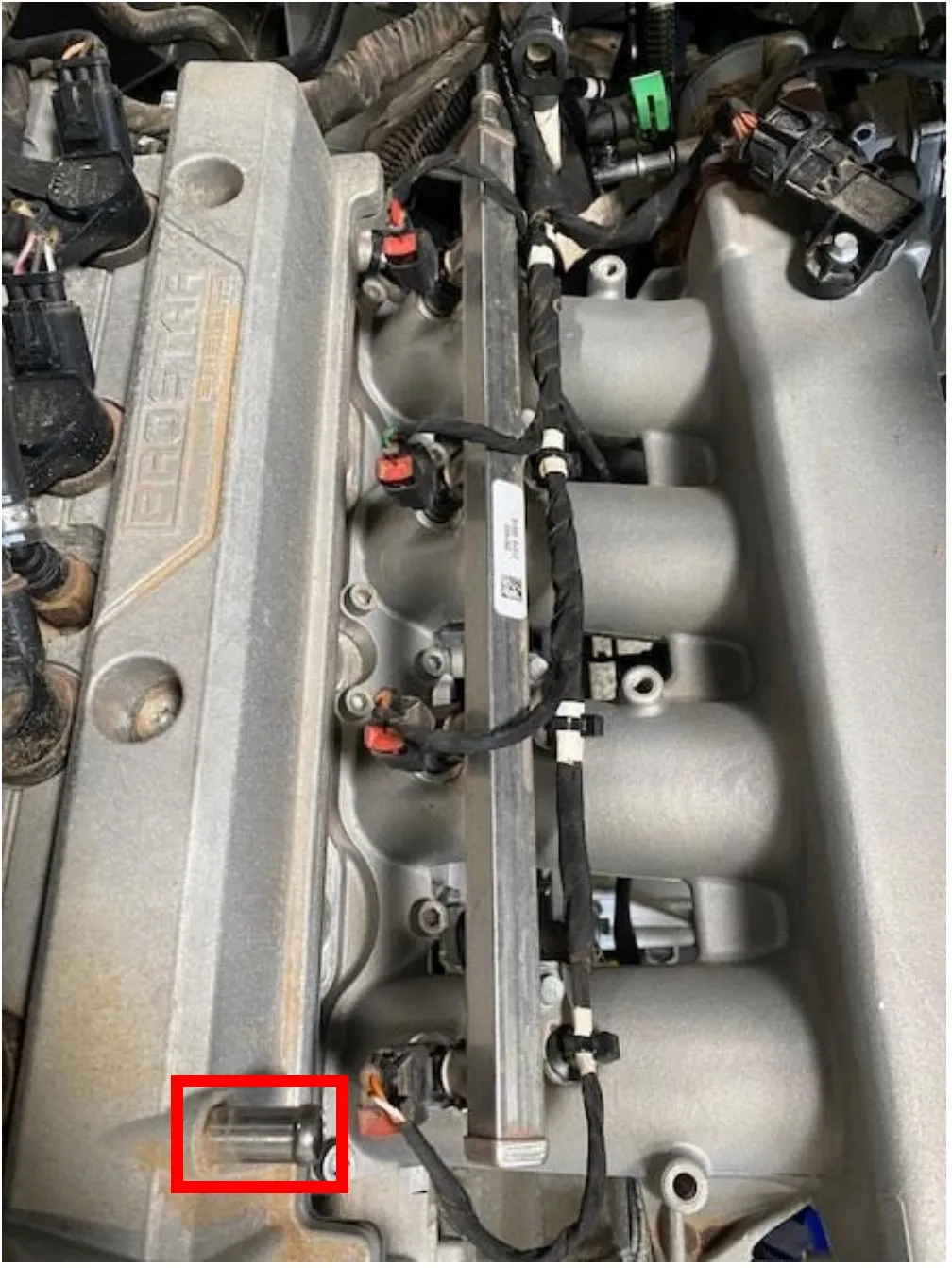
Remove the chain tensioner access panel from the timing chain cover, using an 8mm socket.
- Step 13
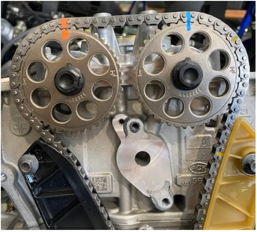
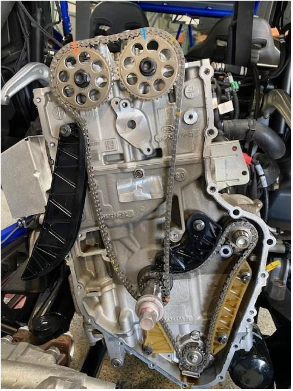
Find top-dead-center on the engine. Ensure the intake and exhaust camshaft notches are in the 12 o’clock position. The number 1 piston should be at top dead center (TDC), crankshaft key at 12 o’clock. The engine is timed top-dead center exhaust stroke. You can also slide the chain tensioner access panel into the key way on both camshafts.
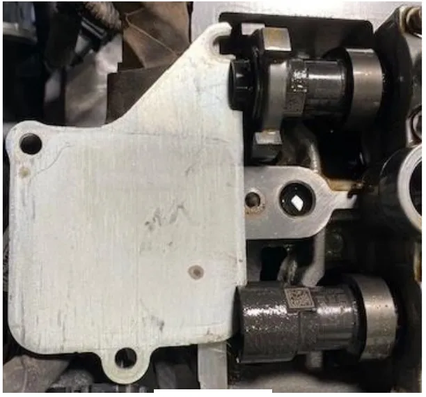
- Step 14
Place a catch pan underneath the timing chain cover. Remove the (20) timing chain cover screws using a 10mm & 6mm Allen socket. The cover may struggle to come off due to the water pump bearing in the cover.
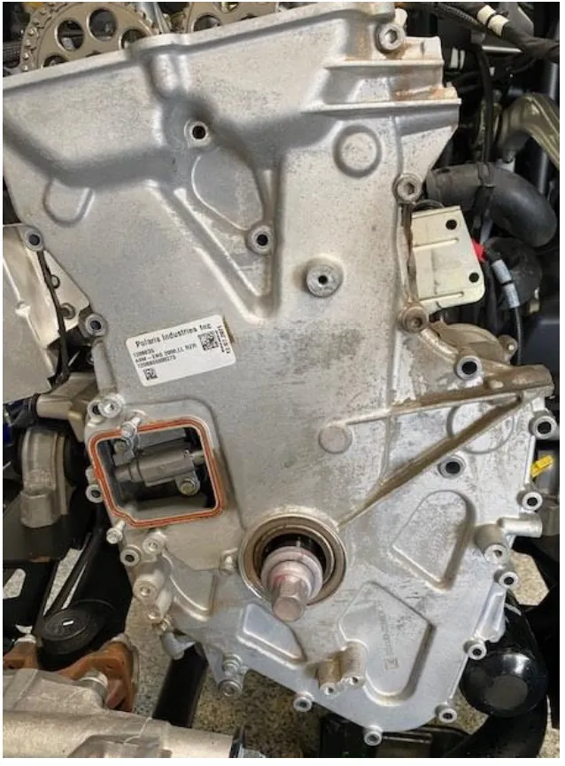
- Step 15
Remove the (2) screws holding the top chain guide using a 10mm socket.
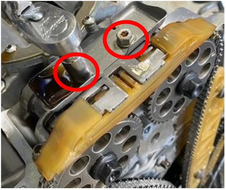
- Step 16
Clean the timing gears and chain with parts cleaner, wipe clean and let dry.
- Step 17
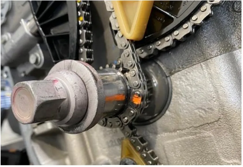
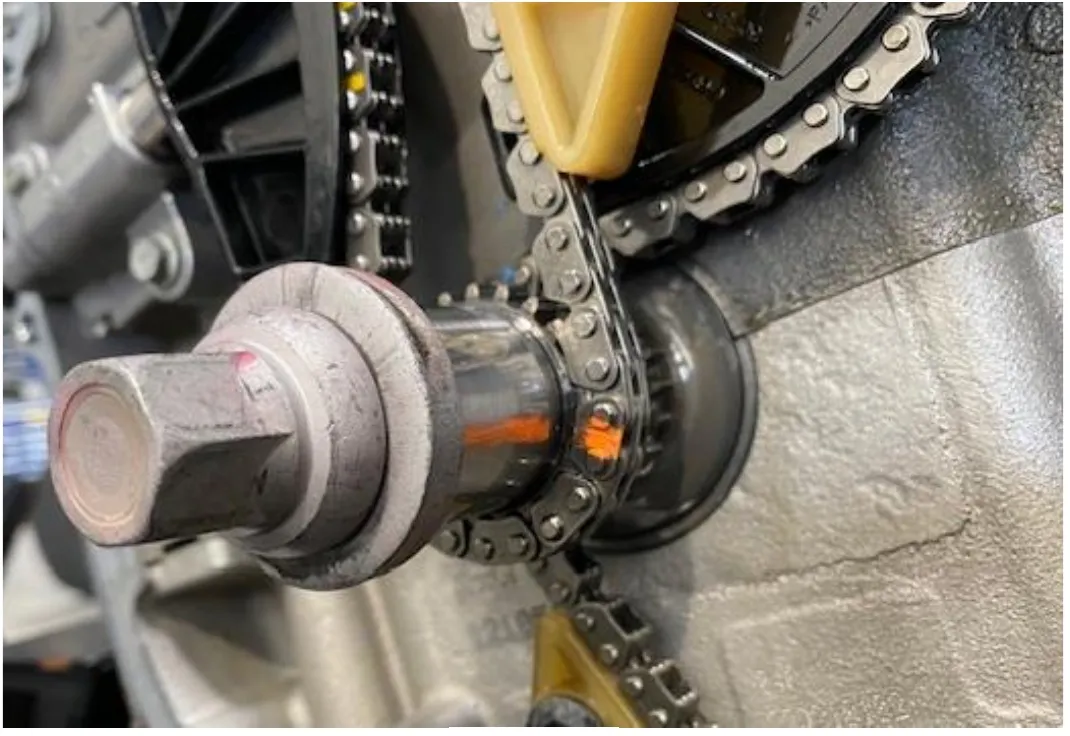
With a paint marker, mark the intake/exhaust cam gears and chain. Also make a mark on the crankshaft and chain. This is for reassembly purposes.
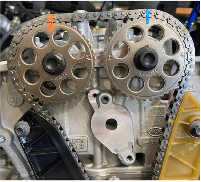
- Step 18
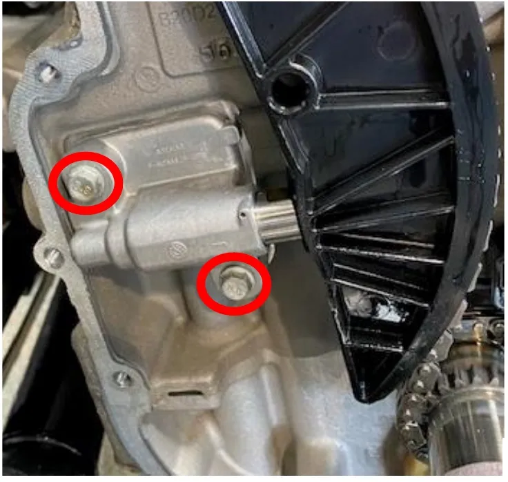
Remove the chain tensioner by removing (2) 8mm screws. When removing the chain tensioner be careful not to damage the piston or spring. This will be reused.
- Step 19
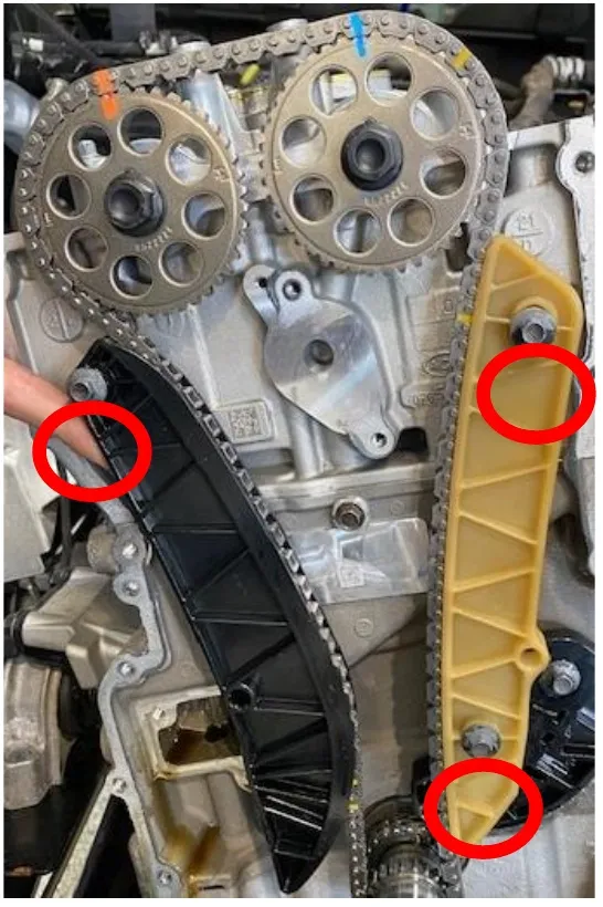
Remove both (black/neutral) chain guides. Total of (3) 8mm bolts. Remove the timing chain off the gears and place it in a safe area.
- Step 20
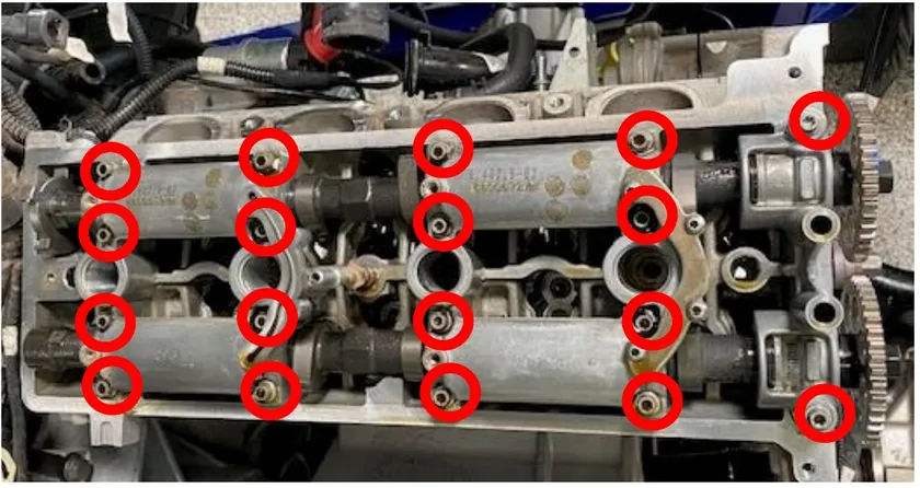
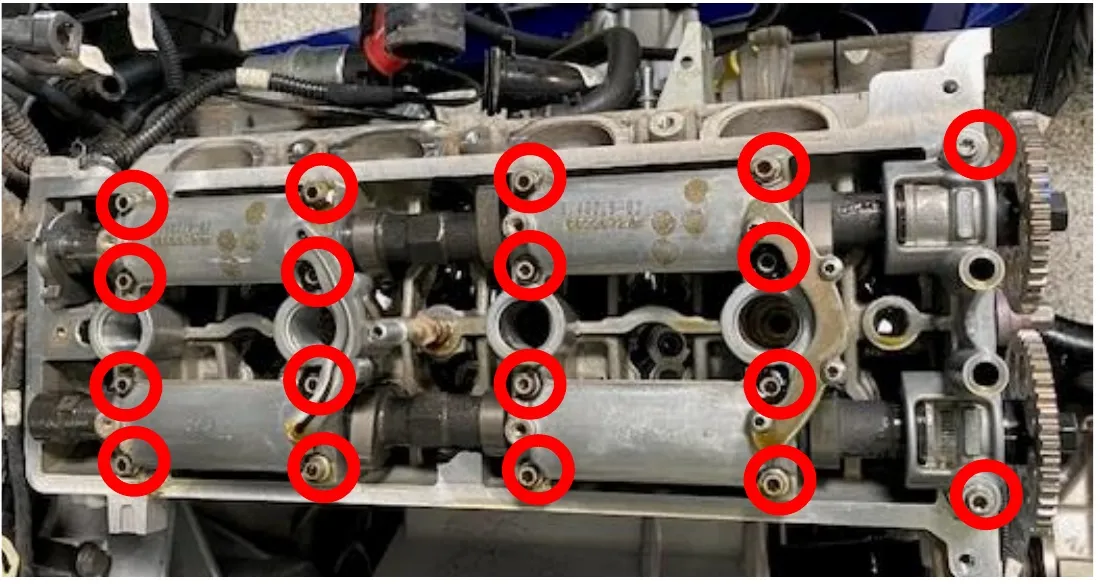
Remove the camshaft carrier fasteners. (18) 8mm and (2) 10mm screws. Remove the intake and exhaust camshafts.
- Step 21
Unplug the camshaft sensor, located on the rear of the engine. Remove the sensor with a 10mm socket.
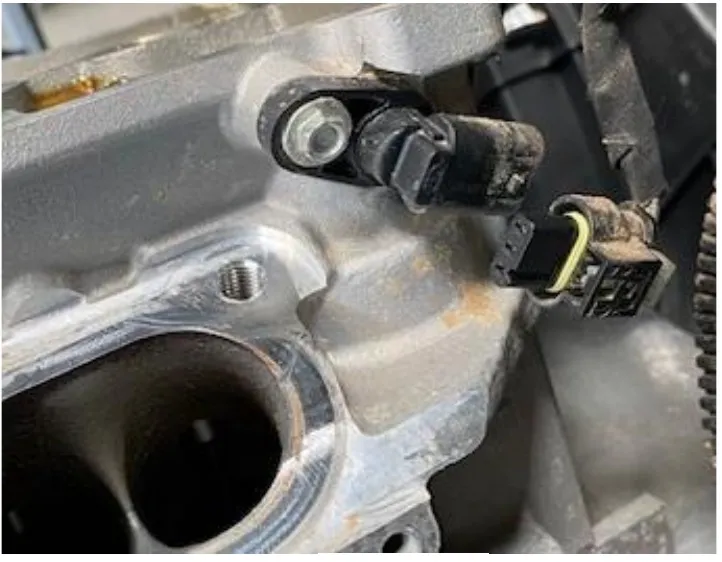
- Step 22
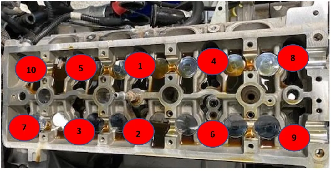
Starting with number 1, remove one head bolt and replace it with a stud at a time so the cylinder head never has more than one bolt/stud loose at a time. Lather both ends of the stud with supplied ARP assembly lube. Hand tighten the stud until it bottoms out. Place assembly lube on both sides of the washer, place the washer on the stud. Finger tighten the nut onto the stud and torque to 80 ft/lbs. See torque sequence and specifications below.
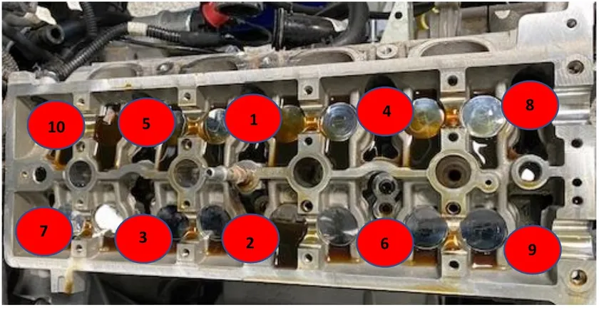
| Torque Specification: Head Stud | 12mm ARP 2000 | 12mm ARP 625 |
|---|---|---|
| Step 1 | 80 ft/lb | 80 ft/lb |
| Step 2 | 100 ft/lb | 100 ft/lb |
| Step 3 | 125 ft/lb | 150 ft/lb |
On final torque go over the pattern a total of (3) times.
Procedure
Pro R Engine Reassembly
- Step 1
Install both intake/exhaust camshafts. Ensure the camshaft notches are in the 12 o’clock position (still at top dead center). Lubricate the camshaft bearing journal surfaces. Install camshaft gaskets and carriers. Torque sequence below.
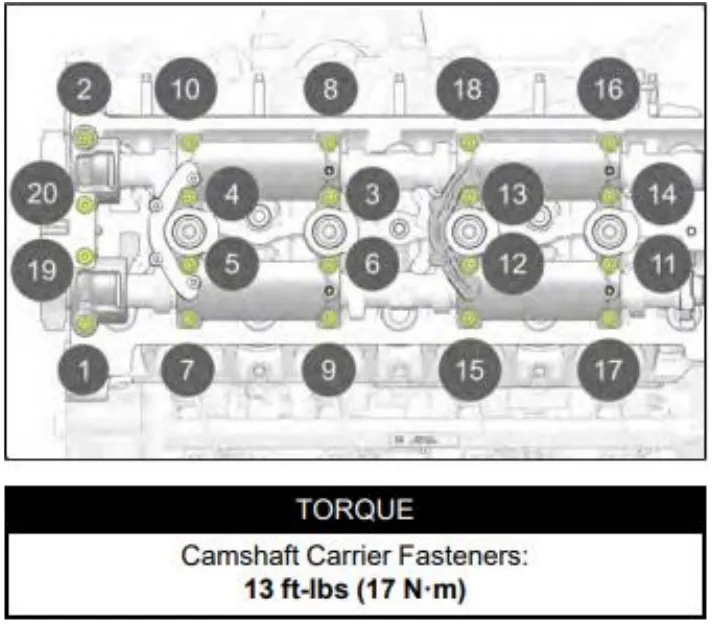
TORQUE. Camshaft Carrier Fasteners: 13 ft-lbs (17 N·m) - Step 2
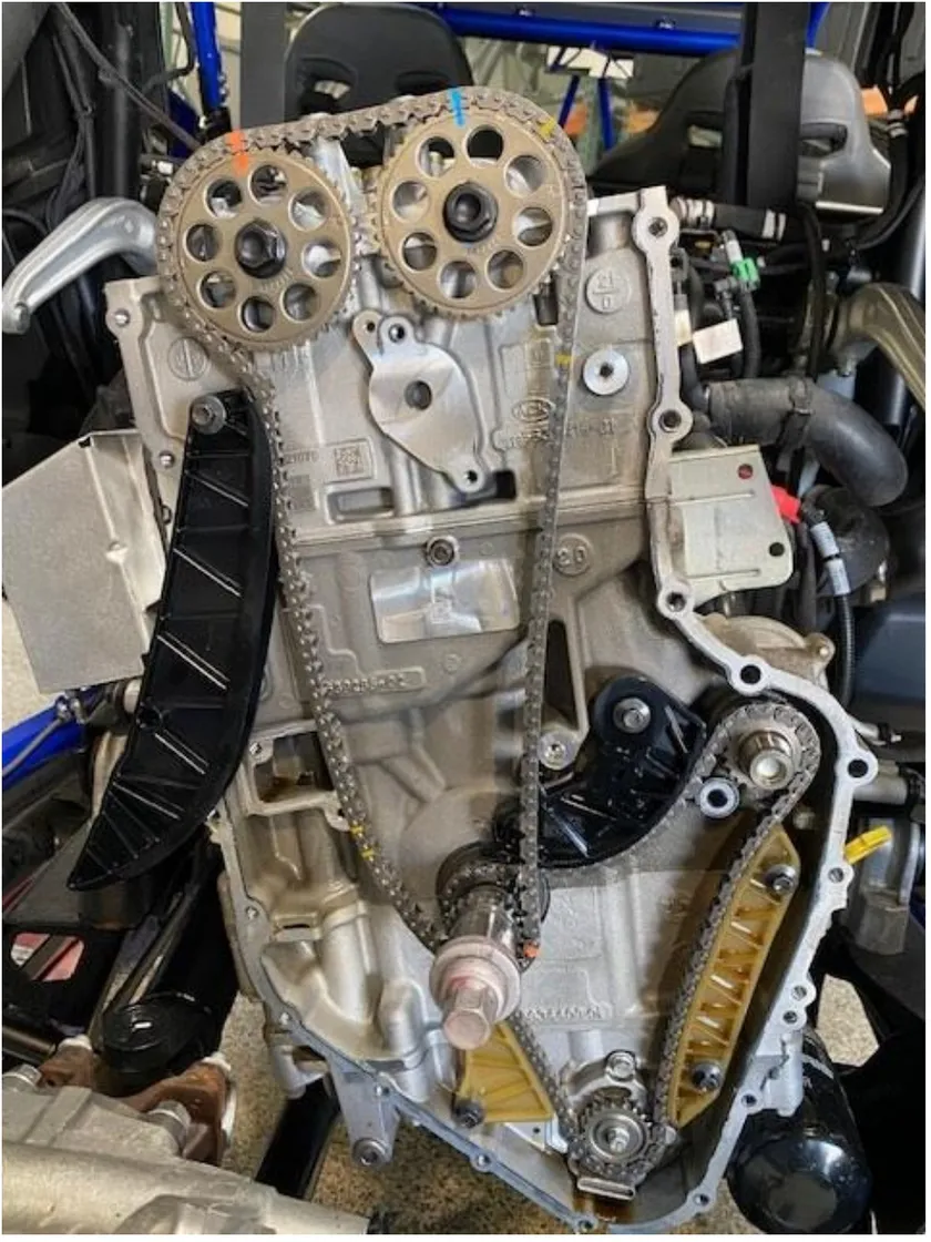
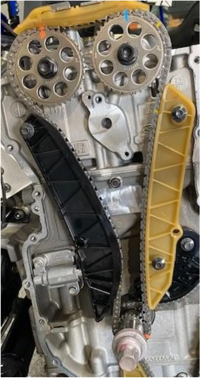
Install the timing chain with indicator marks on both camshaft gears and crankshaft gear. Install the timing chain guides and hand tighten for now. Double check all indication marks are still lined up with top dead center. Torque timing chain guides to 89 in-lbs.
- Step 3
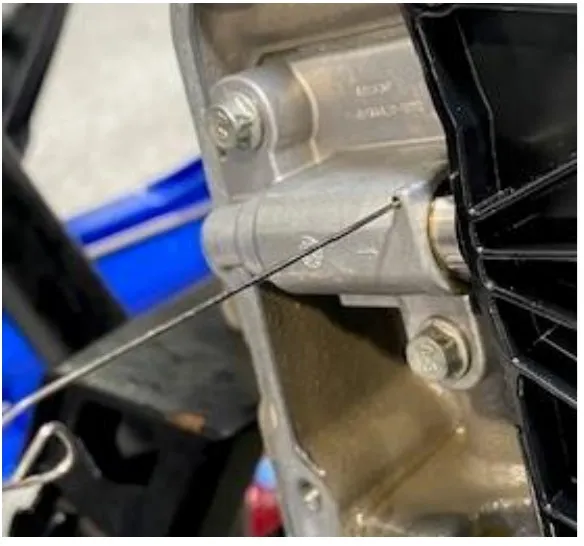
Reset the timing chain tensioner. Remove the piston from the body and dry completely off. Press in and twist clock-wise on the piston until it stays collapsed by itself. Reinstall the piston assembly into the body of the tensioner. Rotate the crankshaft clockwise to remove chain slack. Do not rotate the intake camshaft. Install the tensioner assembly into the crankcase. Torque tensioner fasteners to 80 in-lbs. Press in and release the tensioner piston to allow engagement with the chain guide. If you cannot get the piston to stay, there is a small hole on the body to retain the piston.
- Step 4
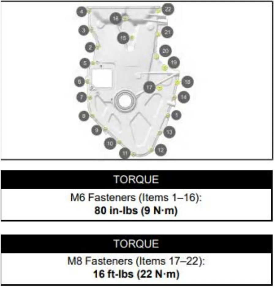
Install the timing chain cover and loosely install fasteners. The longer screws support the water pump. Make sure the pump is seated correctly before torque procedure. Torque sequence below.
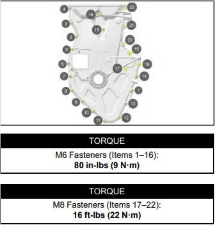
TORQUE. M6 Fasteners (Items 1–16): 80 in-lbs (9 N·m). TORQUE. M8 Fasteners (Items 17–22): 16 ft-lbs (22 N·m) - Step 5
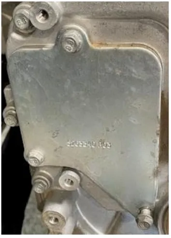
Install the chain tensioner cover. Torque the OEM hardware to 80 in-lbs.
- Step 6
Reinstall the valve cover and gasket. Torque in sequence. 89 in-lbs.
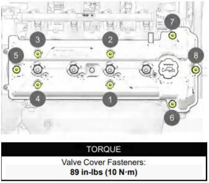
TORQUE. Valve Cover Fasteners: 89 in-lbs (10 N·m) - Step 7
Reinstall the harmonic pulley onto the crankshaft.
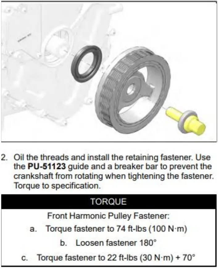
2. Oil the threads and install the retaining fastener. Use the PU-51123 guide and a breaker bar to prevent the crankshaft from rotating when tightening the fastener. Torque to specification. TORQUE. Front Harmonic Pulley Fastener: a. Torque fastener to 74 ft-lbs (100 N·m). b. Loosen fastener 180°. c. Torque fastener to 22 ft-lbs (30 N·m) + 70° - Step 8
Reinstall the alternator stretch belt.
- Step 9
Reinstall the alternator shroud.
- Step 10
Reinstall the alternator stretch belt cover.
- Step 11
Reconnect the coolant lines and fill the engine with coolant.
- Step 12
Reinstall the bed frame, bed, taillights and camera, lower/upper rear valance, muffler tips, muffler, etc.
- Step 13
Start the vehicle and add coolant if needed.
Need technical support?
Submit a ticket with your vehicle and what you're seeing, and our support team will get back to you.
