 BUY NOW, PAY LATER. Starting at 0% APR


Can-Am Maverick R Rising Rate 340 Fuel Pump Conversion Kit
Maverick R Rising Rate 340 Fuel Pump Conversion Kit
In the box
Parts and tools
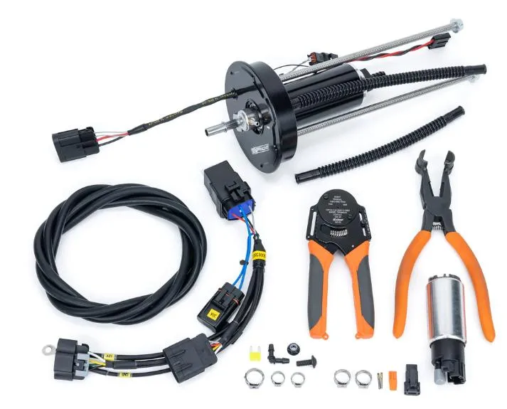
Included parts
- 1EVP Conversion Fuel Pump
- 1Vacuum Hose
- 120 AMP Fuse
- 1Fuel Pump Relay Harness
- 2Hand Tools
- Hardware
Required tools
- 10mm Socket
- T-30 Socket
- Dielectric Grease
- Rags
Included Parts
| Part Number | Description | Quantity |
|---|---|---|
| 500RU0064 | DW 340LPH Compact Style Fuel Pump Kit | 1 |
| 953RU0397 | 5/16 Corrugated Fuel Line 8.0” | 1 |
| 953RU0045 | 13.3mm Pinch Clamp | 3 |
| 500RU0057 | 50mm Inline Fuel Filter, 100 Micron | 1 |
| 500RU0058 | X3 Billet Fuel Hat | 1 |
| 953RU0618 | X3 Fuel Filter O-ring | 1 |
| 953RU0619 | 10 AN ORB to 5/16 Barb Fitting | 1 |
| 953RU0620 | 6AN to 3/8" Straight Quick Connect Fitting | 1 |
| 953RU0622 | 1/8" NPT Plug, Stainless | 1 |
| 953RU0623 | 1/16" NPT Plug, Stainless | 1 |
| 953RU0629 | DEUTSCH Female 2 Position 20 AWG Connector | 1 |
| 953RU0630 | DEUTSCH Terminal for Female 2 Position 20 AWG Connector | 2 |
| 953RU0631 | DEUTSCH Female 20 AWG 2 Position Wedge Lock | 1 |
| 702FC0036 | X3 Billet Fuel Hat Wiring Harness | 1 |
| 953RU0632 | M8 x 1.25 x 270mm, Stainless Threaded Rod | 2 |
| 953RU0633 | M8 x 1.25 Distorted Locknut | 2 |
| 953RU0634 | Corrugated Fuel Hose, 8mm ID x 8mm ID x 250mm Length | 1 |
| 953RU0637 | Circlip 36mm ID, 38.8mm OD | 1 |
| 953RU0638 | M6 x 1.0 x 10mm Stainless-Steel Low-Profile Socket Cap Screw | 1 |
| 500RU0063 | Bosch 4.5 Bar Fuel Pressure Regulator | 1 |
| 953RU0034 | 11.3mm Pinch Clamp | 2 |
| 953RU0037 | 3MM ID Hose | 144 |
| 953RU0038 | 3/16" 90 Degree Hose Barb | 1 |
| 953RU0070 | 15.7mm Pinch Clamp | 1 |
| 705RU0009 | 20 AMP Fuse ATM | 1 |
| 702RC0037 | Maverick R Fuel Pump Relay Harness | 1 |
| 953RU0645 | DTM 20-22 AWG Crimping Tool | 1 |
| 953RU0646 | Corrugated Fuel Hose Tool | 1 |
| 953RU0452 | M6-1.0 x 16mm Flange Button Head Screw, Black Stainless | 1 |
| 953RU0453 | M6-1.0 Nyloc Nut, Aluminum Black Stainless | 1 |
Procedure
Fuel Pump Removal
- Step 1
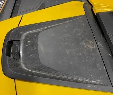
Remove the center dash cover (if it hasn’t already fell off).
- Step 2
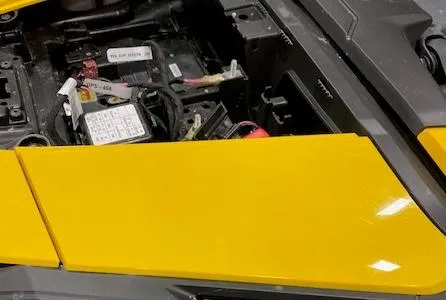
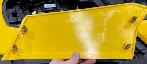
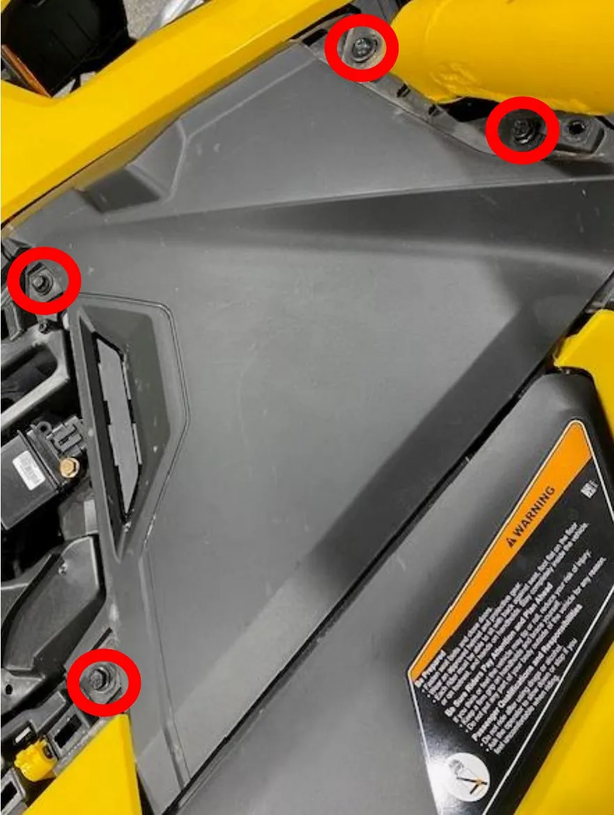
Remove the passenger side yellow panel. Slightly lift on each corner, (4) tabs are holding it in place.
- Step 3
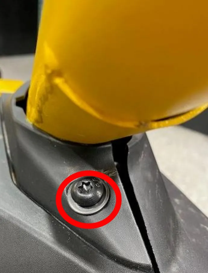
With a T-25 socket, remove the cage trim piece. You can open the fuel door to help remove.
- Step 4
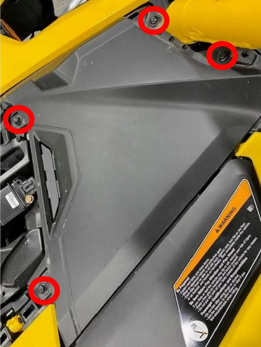
Remove the passenger side upper dash. (3) 10mm screws and (1) T-25 screw.
- Step 5
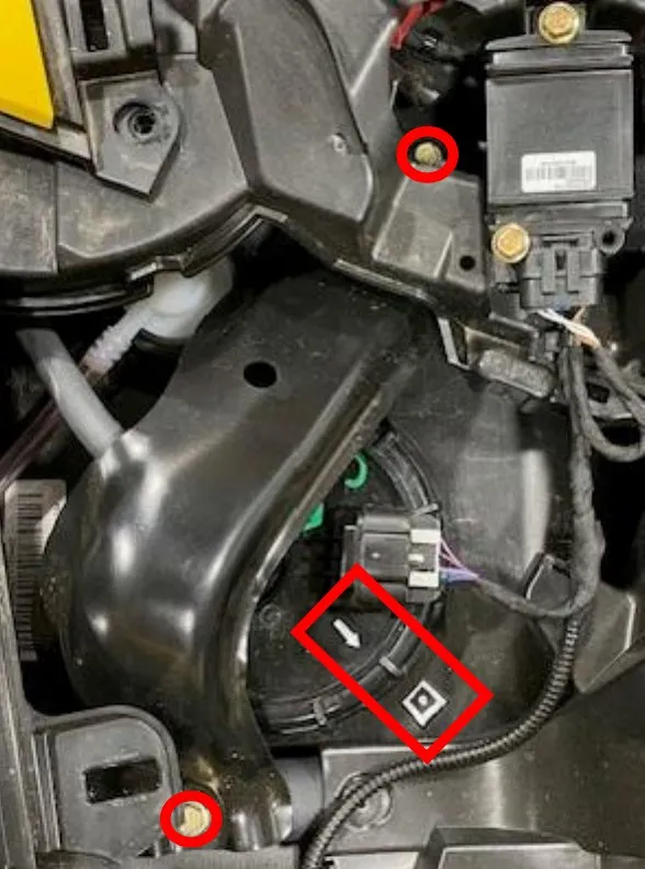
Remove the fuel pump safety bracket by removing (2) 10mm screws.
 Note
Notice the arrow on the fuel pump is facing the middle of the box. When reinstalling make sure the arrow is facing the middle of the box or your fuel float will read incorrectly.
- Step 6
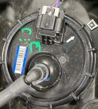
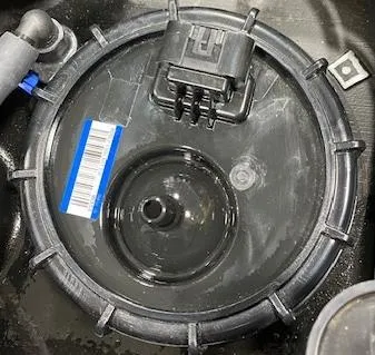
Remove the silver safety clip on the electrical connector, then remove plug. Remove the blue safety clip on the fuel connector, press the black quick connect and remove the fuel hose.
- Step 7
Remove the fuel pump nut, be careful not to damage it. The fuel pump assembly has springs so the hat might spring up about one inch.
NoteIf you are changing fuel octane, now is the time to drain your fuel tank!
Procedure
Fuel Pump Disassembly
- Step 1
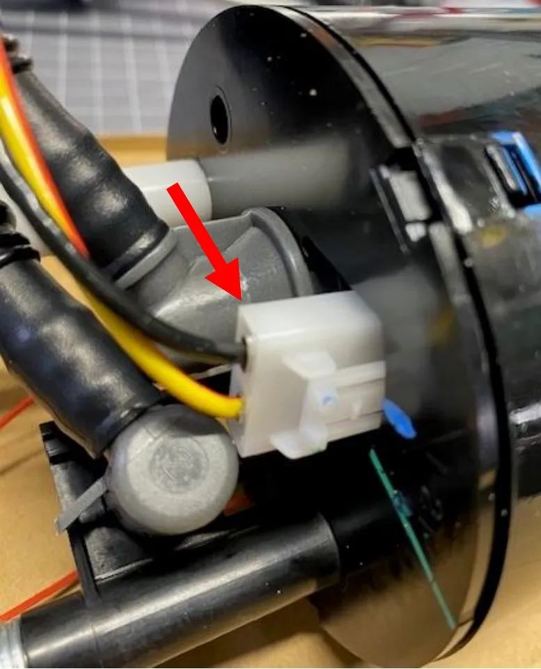
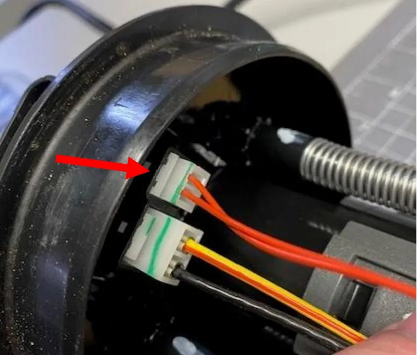
Unplug the fuel pump electrical connector, it wont be able to be removed at this point, as long as its unplugged. Disconnect the fuel float connector from the fuel hat.
- Step 2
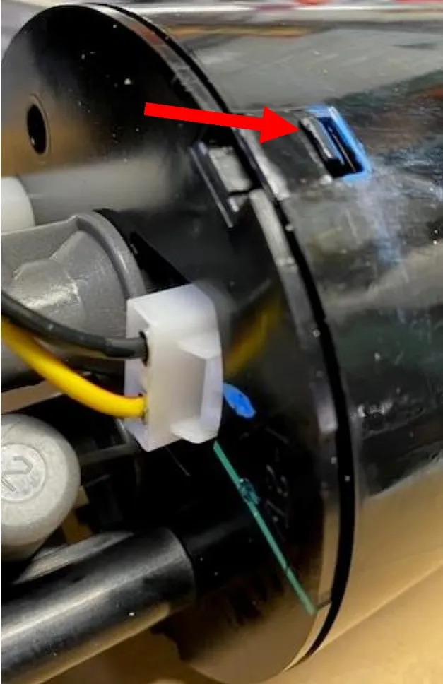
Carefully push down 1 tab at a time on the surge tank, work your way around the top of the surge tank hat. Total of (3) tabs. DO NOT BREAK THE TABS!. Once complete you can slowly pull the top surge tank away from the lower half. BE CAREFUL!
- Step 3
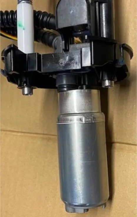
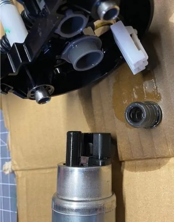
Slide the top hat away from the surge tank. The fuel pump may come with the hat or stay in the surge tank. Remove the fuel pump and rubber grommet from the lid.
- Step 4
Compress the lid and springs a bit, remove the locking washer. Remove the lid from supports. Keep the springs!
- Step 5
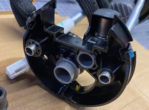
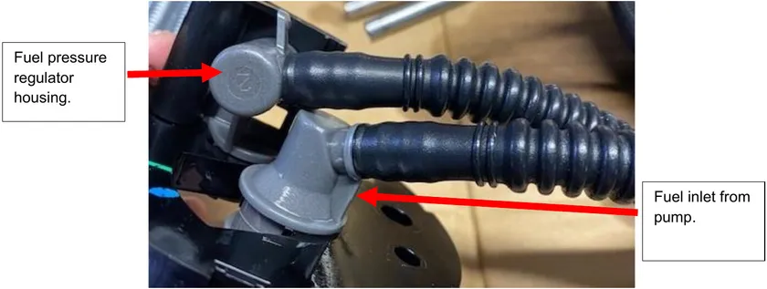
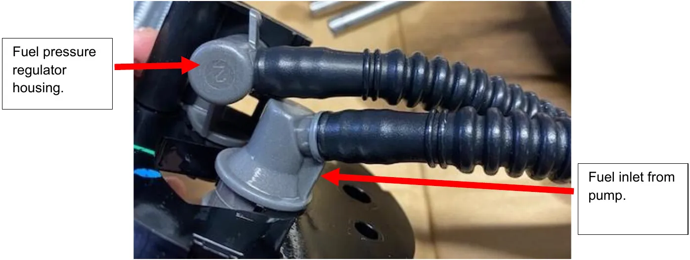
On the lid you will find the fuel inlet and fuel pressure regulator. Cut both hoses off the grey fittings. Keep both black hose sleeves.
 Caution
Don’t cut the grey fittings, be careful!
- Step 6
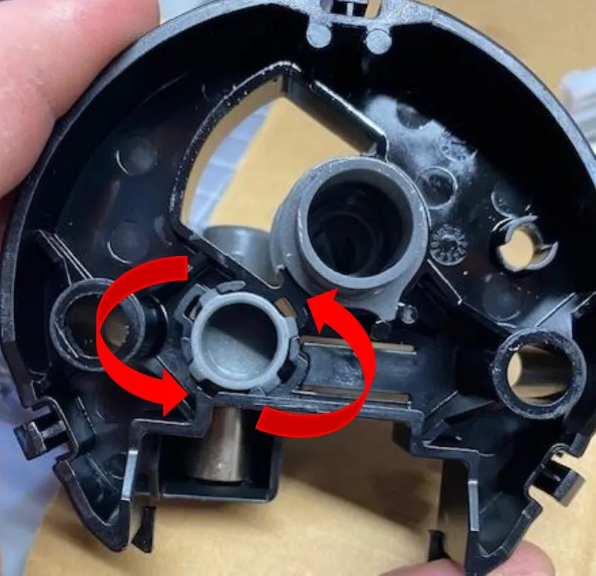
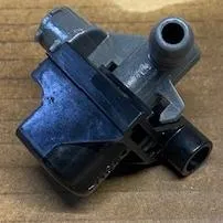
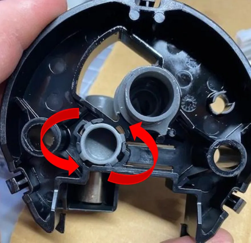
Remove the fuel pressure regulator by turning the grey fitting 1/16 of a turn counterclockwise. Then push up and remove, you can discard this part.
- Step 7
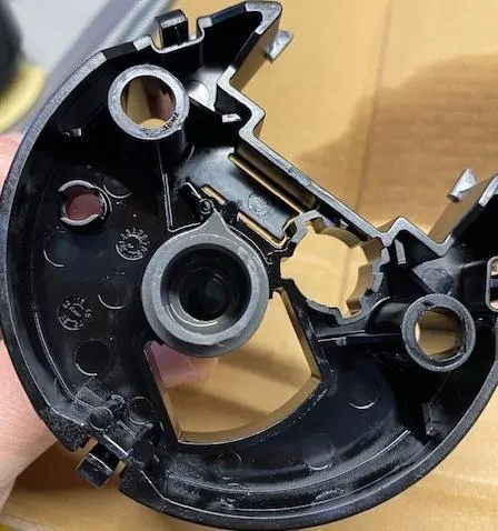
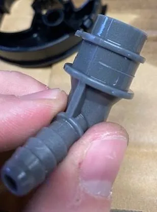
Remove the fuel inlet fitting. Notice it clicks into place between (2) tabs. Turn it counterclockwise, find the two flat sides and remove the fitting from the lid.
- Step 8
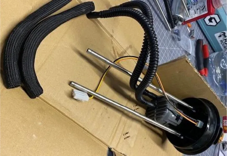
Discard the upper fuel hat, save the black sleeve.
- Step 9
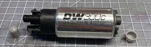
Remove both fuel pump caps before installation.
- Step 10
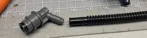
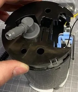
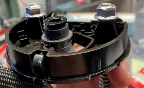
Install the 8.0” corrugated fuel hose onto the grey fitting. It helps to apply dielectric grease onto the pump. Use supplied corrugated hand tool. Heat up the end of the fuel hose with a heat gun NOT A FLAME! You can notice the color turn shiny, remove heat source, let it cool for a few seconds. Install onto the fitting, use supplied 13.3mm pinch clamp to secure.
 Note
the grey fitting and rubber grommet will be reused.
- Step 11
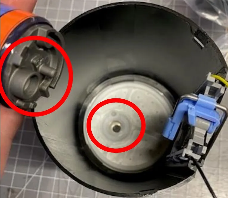
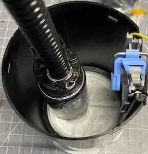
Install the new pump into the bottom surge tank. Make sure both tabs are locked into place. The pump shouldn’t move when properly locked into place.
- Step 12
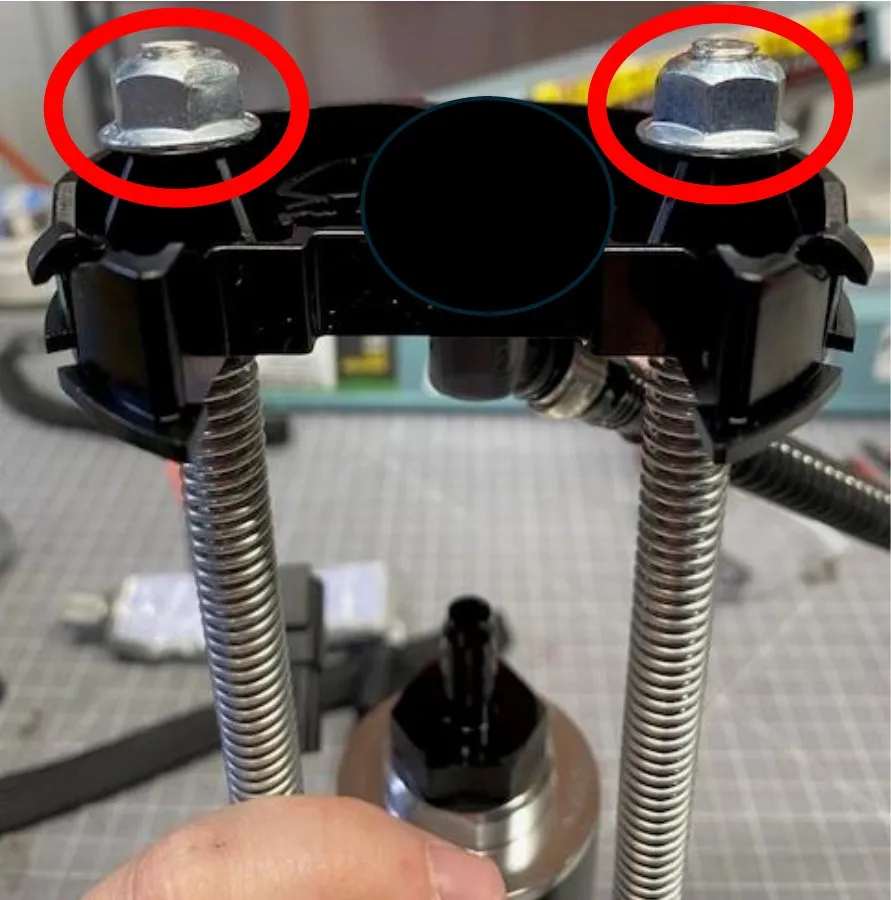
Install the springs onto the new supplied fuel hat. Reinstall the lid to the fuel hat supports. Make sure orientation is correct, figure 26, otherwise the hat will be off-center. Push down and compress the springs slightly, install supplied distorted lock nuts so 2 threads show.
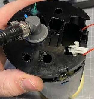
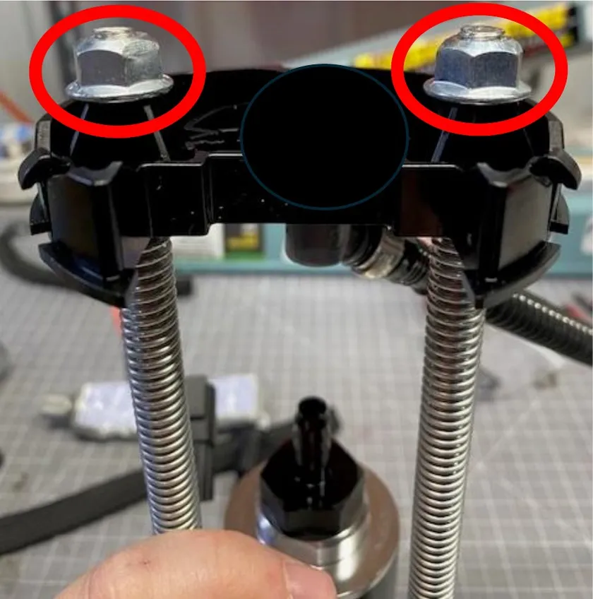
Fig. 26 
- Step 13
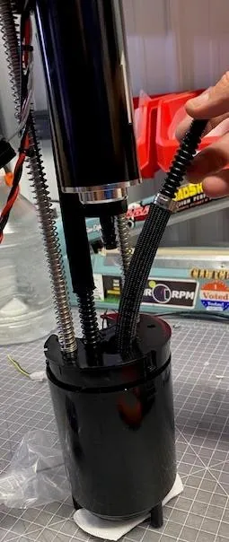
Slowly reinstall the upper lid to the surge tank, making sure all (3) clips meet and fuel pump and inlet meet. Watch the float wires. May help to pull the corrugated fuel hose to the side.
- Step 14
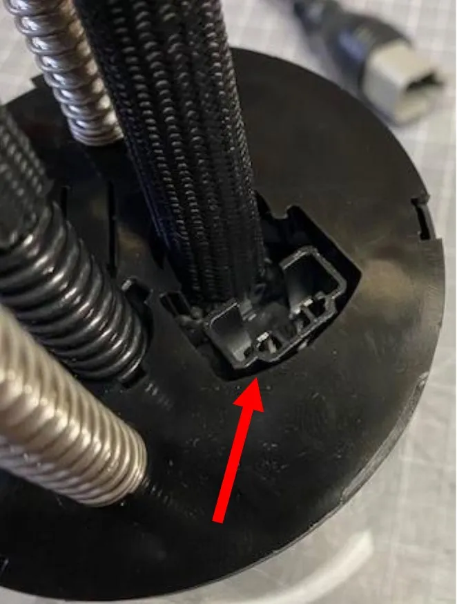
You may need to orientate the fuel pump so the lid doesn’t interfere.
- Step 15
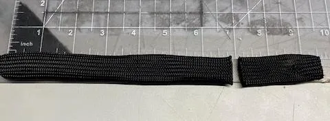
Trim 2.0” off both sleeves, should be 7.0” in total length. Burn the ends you cut with a flame. Slide one sleeve onto the fuel return hose, and the other will be used on the fuel inlet hose.
- Step 16
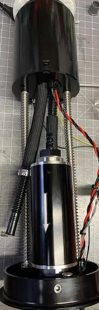
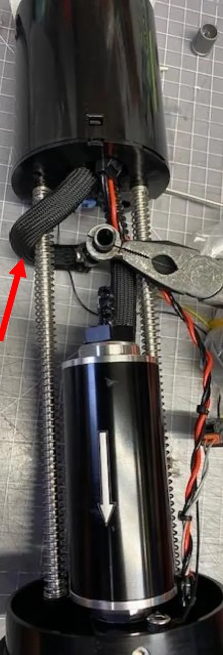
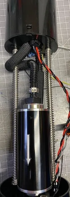
Install sleeve and 13.3mm pinch clamp onto the fuel inlet hose. Notice orientation of hose. Apply dielectric grease to fuel filter inlet fitting. Heat up the hose with a heat gun and install. Secure pinch clamp when done.
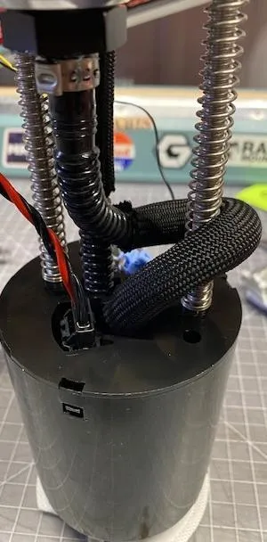
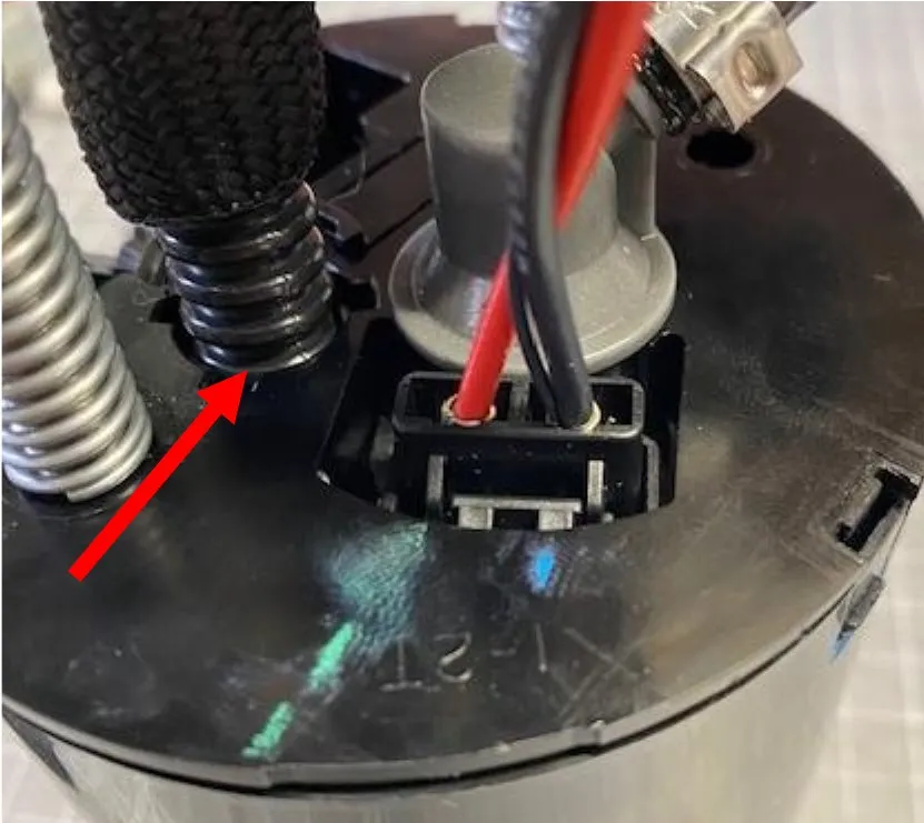
- Step 17
Install the fuel pump connector, you will hear a click. Install the fuel return hose into the OLD fuel pressure regulator hole.
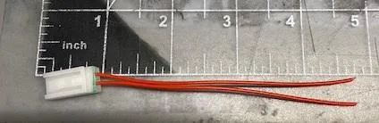
- Step 18
Cut off 5.0” from the float white connector that plugged into the OEM hat.
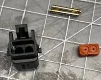
- Step 19
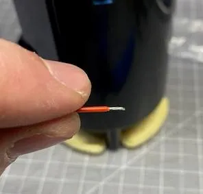
You have (2) terminals, a connector and wedge lock. Remove the orange seal if still installed in connector. Strip 1/4" of the 20awg float wire attached to the float.
- Step 20
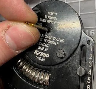
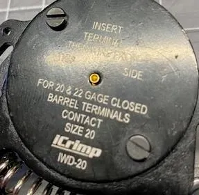
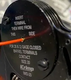
Install the barrel connector into the supplied hand tool. The wire goes into the shallower side, that’s the side you want to see once the terminal is inserted into the tool. Make sure the tool is 100% open. Do this by squeezing the tool all the way shut, it will open all the way when your hand is released. Install the wire into the terminal and squeeze the handle 100% closed. Release.
- Step 21
Install the terminals into the connector, from the backside. You will push until you hear a click. Orientation does not matter on this connector. 1 & 2 can be flip flopped. The terminals will be loose until you install the wedge lock. Install the wedge lock from the front.
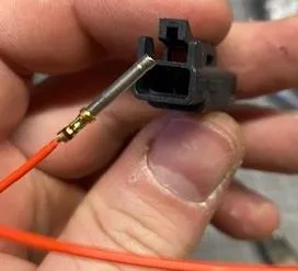
Install terminals through the backside of the connector. 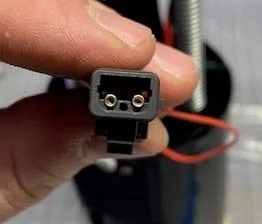
Front side of connector. 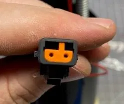
Install the wedge lock from the front side of connector. - Step 22
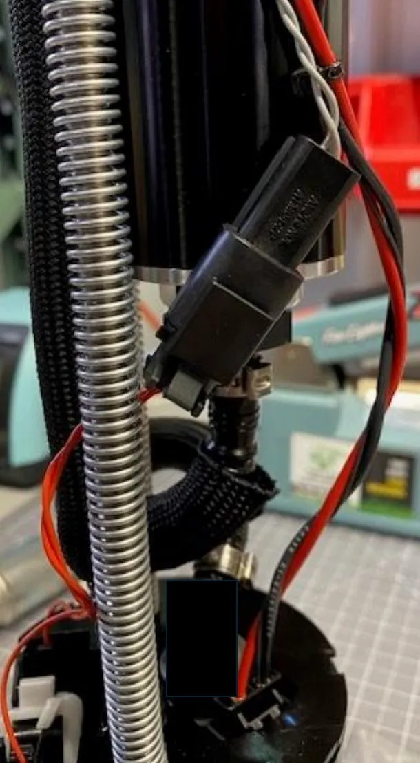
Connect the float connectors.
- Step 23
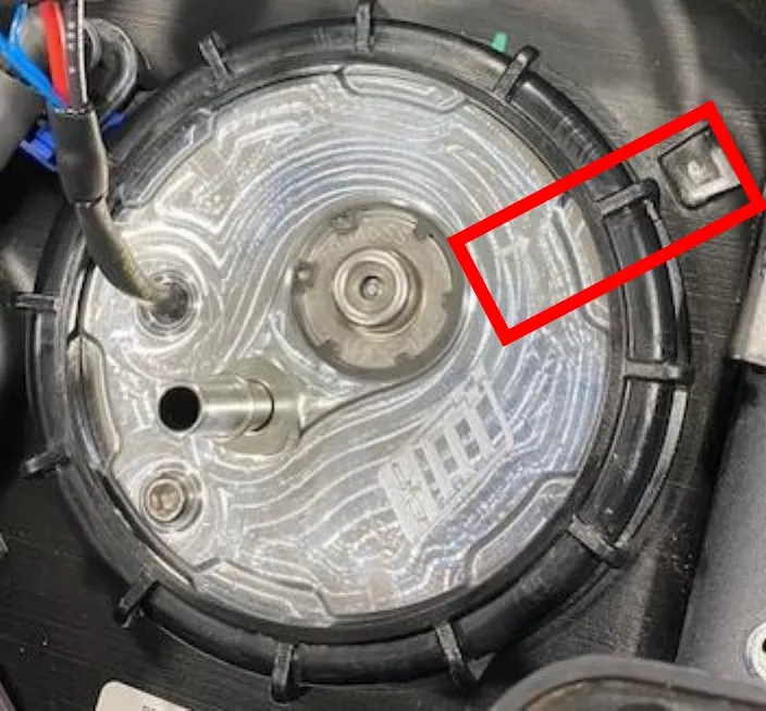
Install the new fuel pump assembly with a seal. Apply dielectric grease on the seal. Clock the fuel pump assembly correctly.
- Step 24
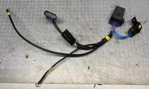
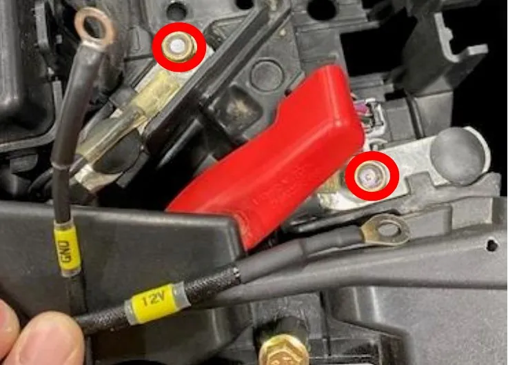
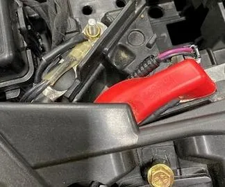
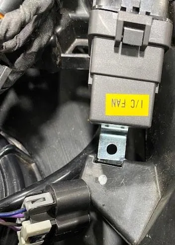
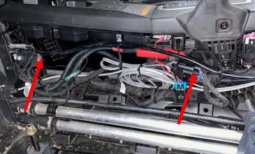
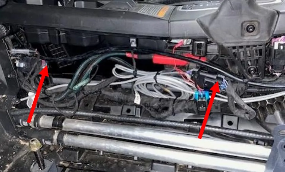
Install the fuel pump relay harness into the vehicle. Use the positive and negative to the upper dash bus bar. Route the wires under the plastics, use a 10mm socket.
- Step 25
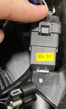
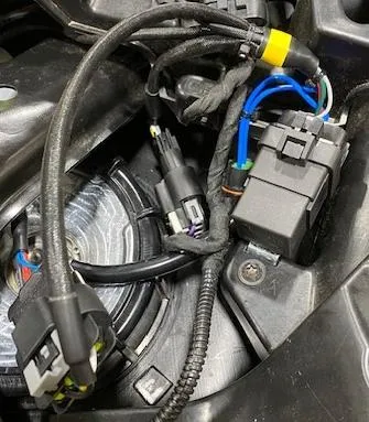
Locate the plastic opening right in front of the fuel pump. Install the relay mounting clip into the slot. Mark with a sharpie and drill a 1/4" hole. Install supplied M6 flange screw and nut. Install the fuel pump harness to the fuel pump and OEM harness.
- Step 26
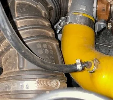
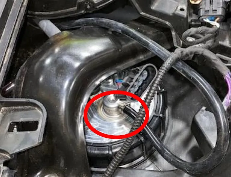
Install supplied 3/16” 90-degree or straight barb into the charge tube, use supplied pinch clamp to fasten. Install vacuum hose and clamp to the barb, route the hose through the firewall and up through the center tunnel, up the dash and to the fuel pump regulator. Loosely zip tie the hose (without kinking). 2-seat models can cut off extra 50” vacuum line. 4-seat models will use all 144”.
- Step 27
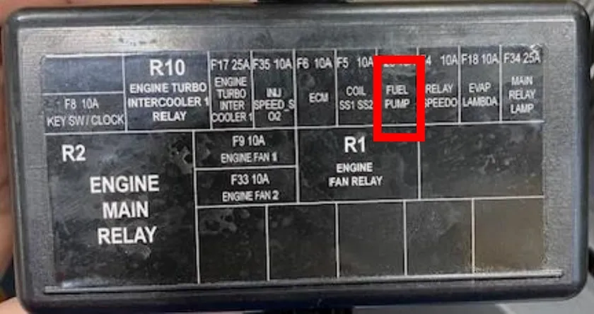
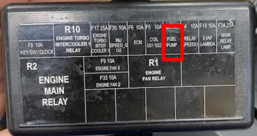
Behind the driver’s seat you will find the fuse box. Locate the fuel pump fuse (F28), replace the 10amp with supplied 20amp.
Plug the CodeShooter device into the vehicle and UPDATE your tune file for the rising rate fuel pump assembly. If you are changing your tune file make sure you have the correct fuel octane in the vehicle!
- Step 28
Key the vehicle on a few times and look for fuel leaks. If everything checks out reinstall all plastics.
Need technical support?
Submit a ticket with your vehicle and what you're seeing, and our support team will get back to you.
