 BUY NOW, PAY LATER. Starting at 0% APR


You will keep all mounting hardware and wastegate hardware. DO NOT SEND THIS WITH YOUR TURBOCHARGER!
Can-Am Maverick R P48-415 Turbocharger Upgrade System
Maverick R P48-415 Turbocharger Upgrade System
Before you start
Note
Your MG1 ECU must be Unlocked by EVP to enable proper tunes for this turbocharger upgrade.
| Level | Tunes | Max Boost (psi) | Spark Plug Gap | Spring | Waste Gate (psi) | Engine HP |
|---|---|---|---|---|---|---|
| P46-335 | 91, MS-109, E85 | 21, 30, 32 | .020” | N/A | Electronic | 366WHP 416CHP(E85) |
In the box
Parts and tools
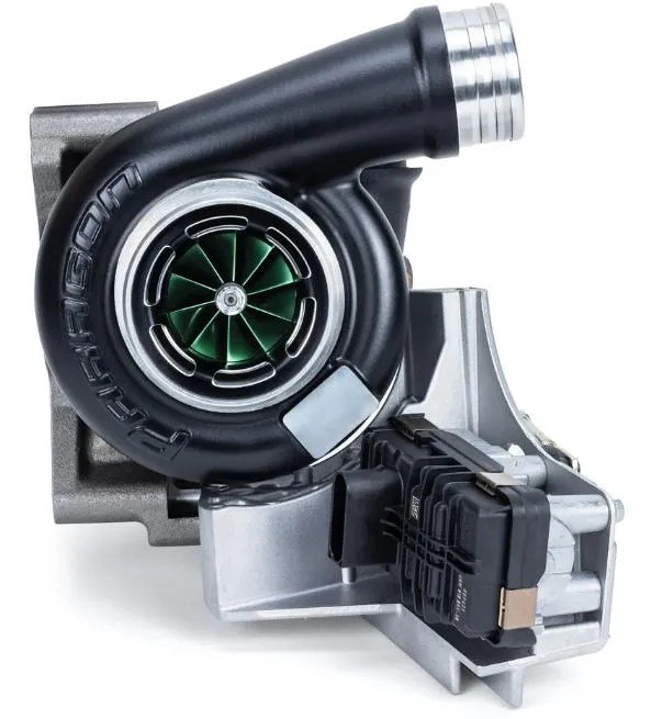
Parts Included in Paragon 48-415 Turbo Upgrade System
- Maverick R Blow Off Valve (BOV) Kit1532010013
- Maverick R Charge Tube Kit, Black1532010009
- Maverick R Stock Turbo High Flow Intake Kit (HFI)1792010004
- X3 1000cc Injectors, Set of 32512010001
- Maverick R P48 Turbocharger2751010017
- X3 4 Bar MAP Sensor Kit3002010008
- Maverick R Fuel Pump Assembly with 340LPH Pump, 4.5 Bar Regulator2501010002
- Maverick R Big Turbo Power Flash with Launch Control and Transmission1012010205
- Maverick R Big Turbo Spark Plug, Set of 33552010004
- 2024 or 2025 Maverick Max R ECU Unlock1261010003
- Maverick R OEM Turbocharger Gasket3501010057
- Maverick R Catch Can Kit1562010006
- Maverick R Plenum Clamp Kit1792010002
Required accessories
- EVP or other Full Turbo Back Exhaust System
Procedure
Installation
- Step 1
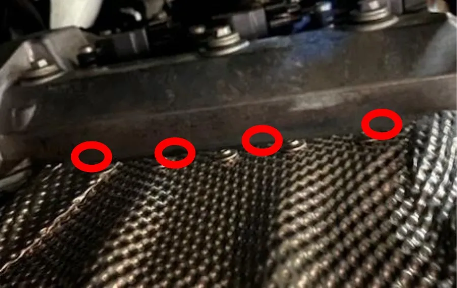
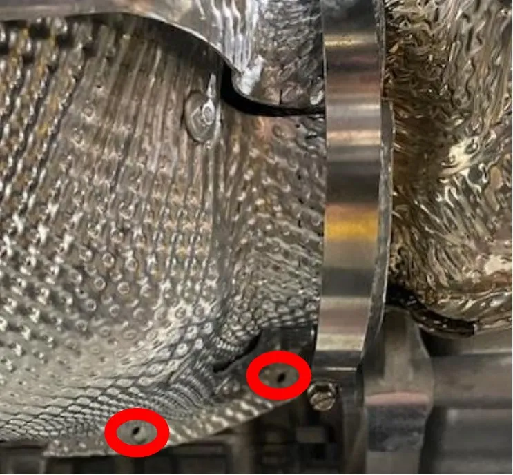
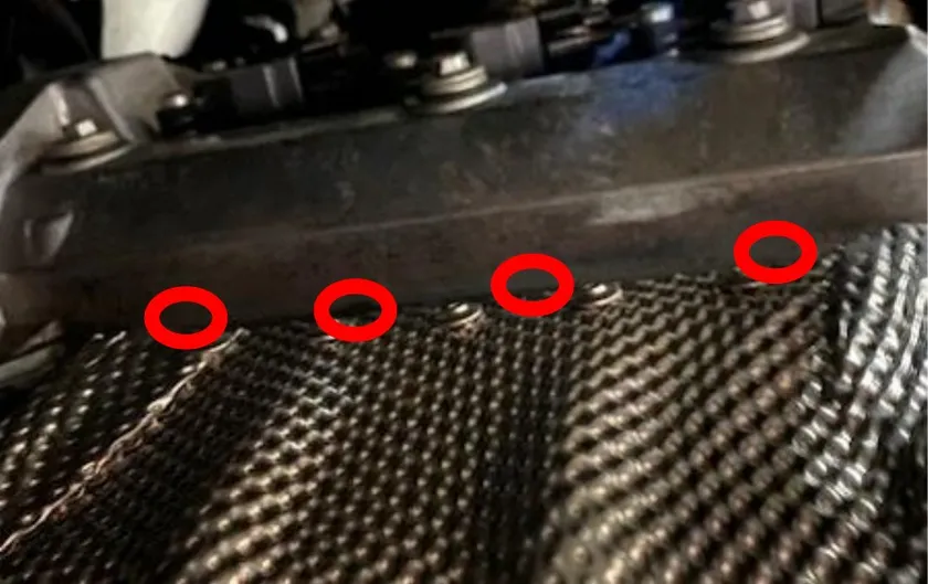
Remove the heat shields (2 part) around the turbocharger. 1 hose clamp, (2) 10mm screws underneath and (4) on top by the valve cover.
- Step 2
Unplug the 02 sensor from the engine harness. If you are running a shocker, unplug the actuator plug as well.
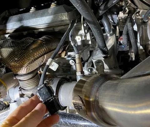
- Step 3
Remove the heat shield located on the downpipe. (3) 10mm screws.
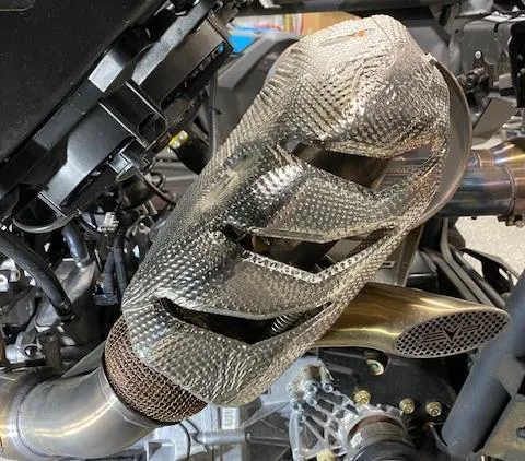
- Step 4
Remove the (4) exhaust springs holding the downpipe to muffler. Loosen the V-band clamp holding the downpipe onto the turbocharger. Use a 13mm socket, lightly tap the V-band if stuck. Do not bend this clamp. Remove downpipe.
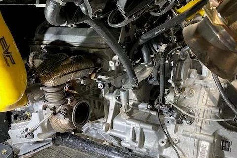
- Step 5
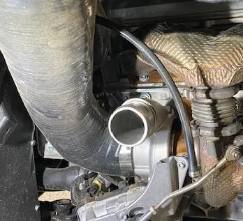
Remove the turbocharger to intercooler charge tube, (2) 11mm nuts. If you are running a rising rate setup, remove the vacuum line. Remove the intake tube, valve cover breather if not running a catch can, either OEM airbox or high flow intake.
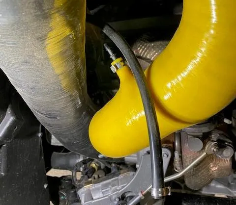
- Step 6
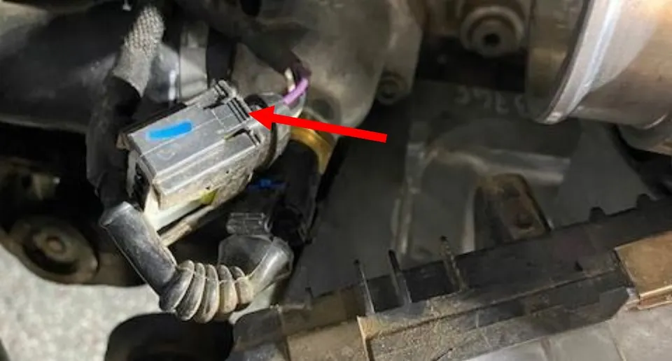
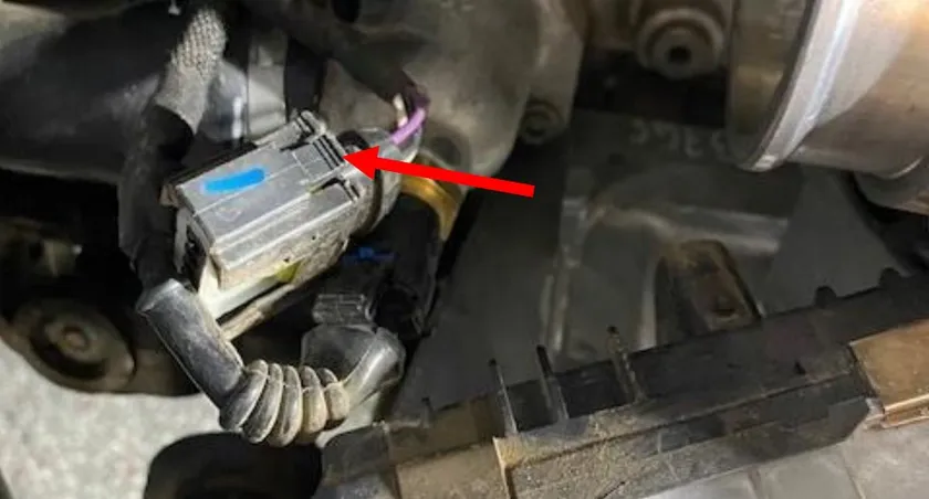
Unplug the electronic wastegate connector. There are (2) tabs, one on top and one on bottom. Press together and remove.
- Step 7
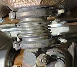
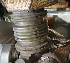
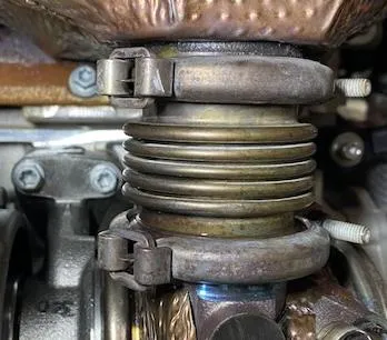
Remove both V-band clamps holding the flex jointer from the header to turbocharger. Take note on where these clamps are orientated. Use a 10mm socket.
- Step 8
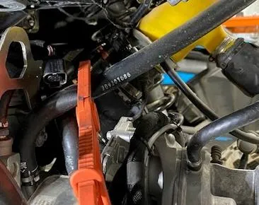
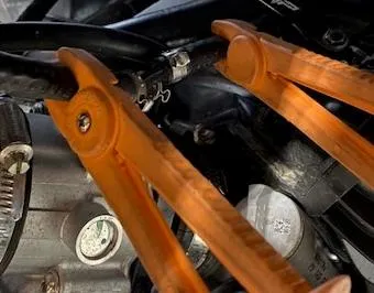
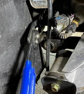
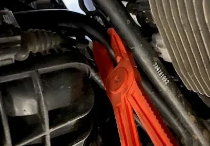
Remove the cap off the coolant reservoir. Pinch off all coolant lines going to and from the engine. A total of 5 clamps, going to the head, lines running up to the radiator and intercooler located by plenum, large hose by the temperature sensor, and hose between the firewall and plenum.
- Step 9
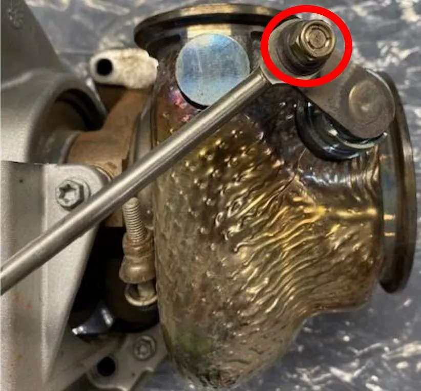
CAREFULLY remove the 10mm nut holding the wastegate rod to the flapper. Remove the nut, washer and inner sleeve. USE PB Blaster and let it sit!
- Step 10
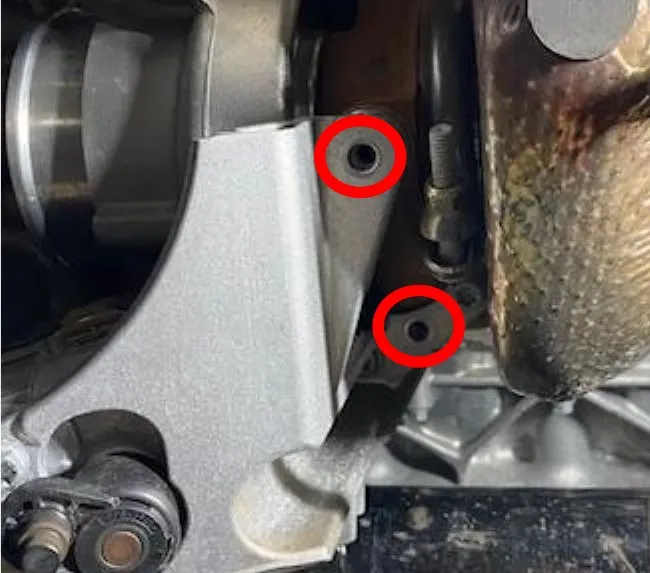
Remove (2) 8mm screw holding the wastegate bracket onto the turbocharger.
- Step 11
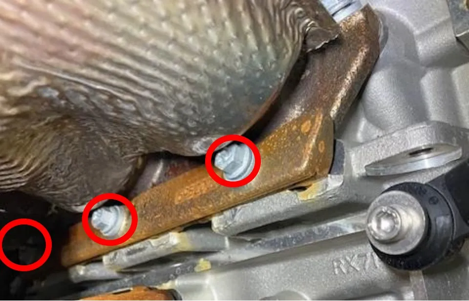
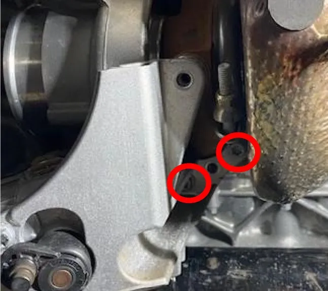
Remove (2) 10mm turbocharger mounting screws on the bottom. Remove wastegate bracket and rod.
- Step 12
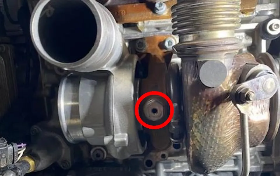
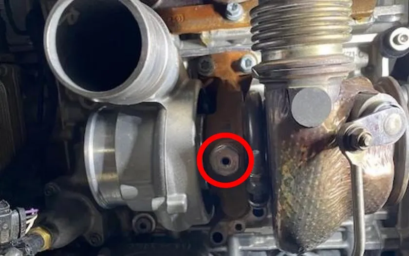
Place a catch pan underneath the vehicle. With the wastegate bracket removed, you can now access the coolant drain plug on the turbocharger. Use a 17mm socket, slowly remove the plug and copper washer.
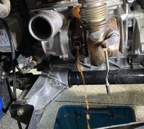
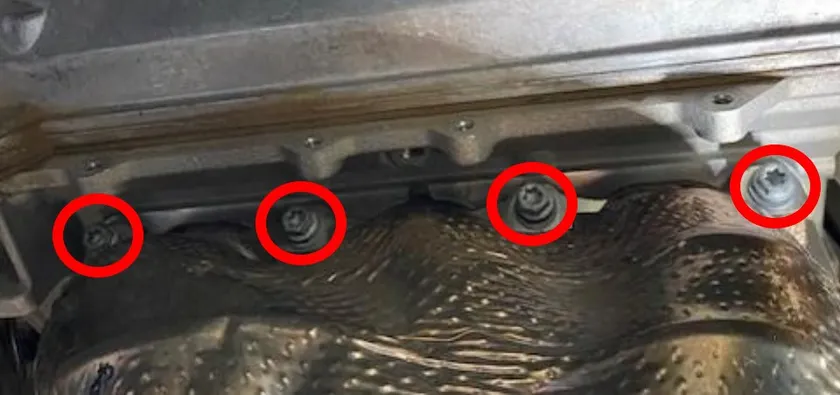
- Step 13
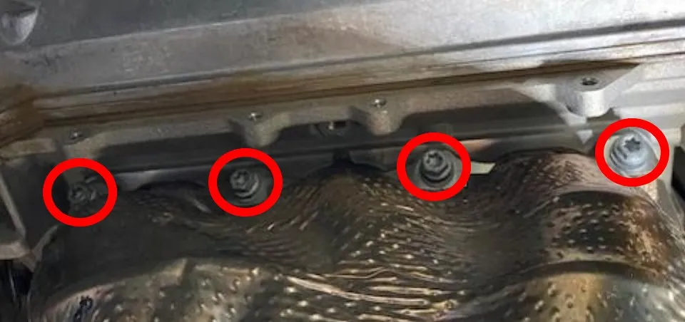
Remove (4) 10mm screws on the top of the header.
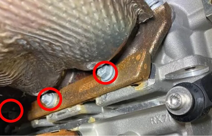
- Step 14
Loosen the bottom pinch plate screws holding the header to the block. You may need to indent the heat shield to get a socket on the screw.
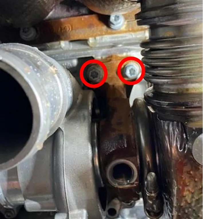
- Step 15
Remove the (2) top 10mm turbocharger screws.
- Step 16
Wiggle the turbocharger off the (2) locating pins while lifting the header up slightly. You do NOT need to remove the header. There is a pipe between the header and turbocharger.
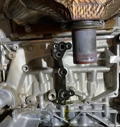
- Step 17
Keep the compensator and (2) gaskets. If torn or bent, you must get new.
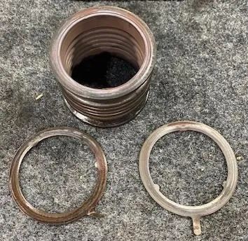
- Step 18
Clean up the turbocharger mounting location and gasket. Remove old gasket and replace with supplied gasket. Make sure the compensator tube is bottom out in the exhaust manifold or turbocharger. If not, remove and clean and reinstall with turbocharger. Sometimes they will get pinched sideways.
- Step 19
Install the coolant plug and sealing washer into the turbocharger, torque to 22 ft-lb. This is what you will be sending to Evolution Powersports.
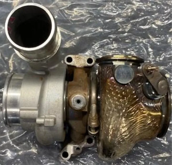
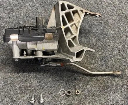
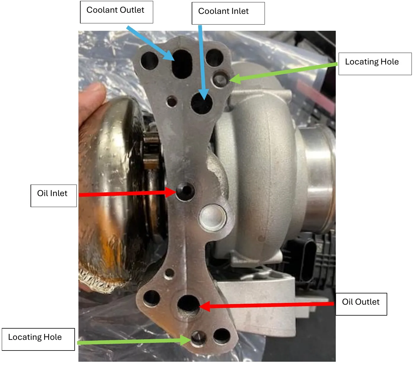
Note
TAPE OVER BOTH COOLANT AND OIL INLET/OUTLET BEFORE YOU PUT ON SHELF
Note
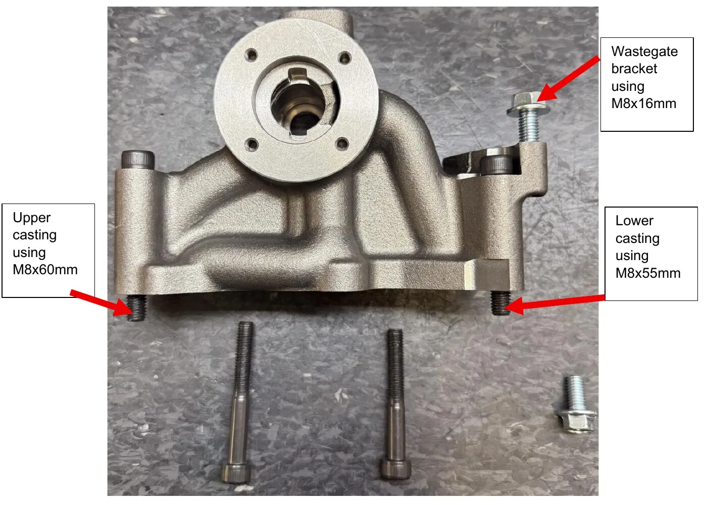
There will be new hardware for mounting the P48 turbocharger.
- (2) M8-1.50x60mm will bolt the UPPER casting of the turbocharger
- (2) M8-1.50x55mm will bolt the LOWER casting of the turbocharger
- (2) M8-1.50x16mm will bolt the actuator bracket to the casting
- Step 21
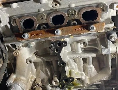
Remove the header and inspect the gasket. If torn, replace. Reinstall header into the pinch plate. Install new turbocharger gasket if you haven’t already.
- Step 22
Install the new turbocharger without wastegate, with the compensator and gaskets. Install all (4) turbo mounting screws. Torque spec below.
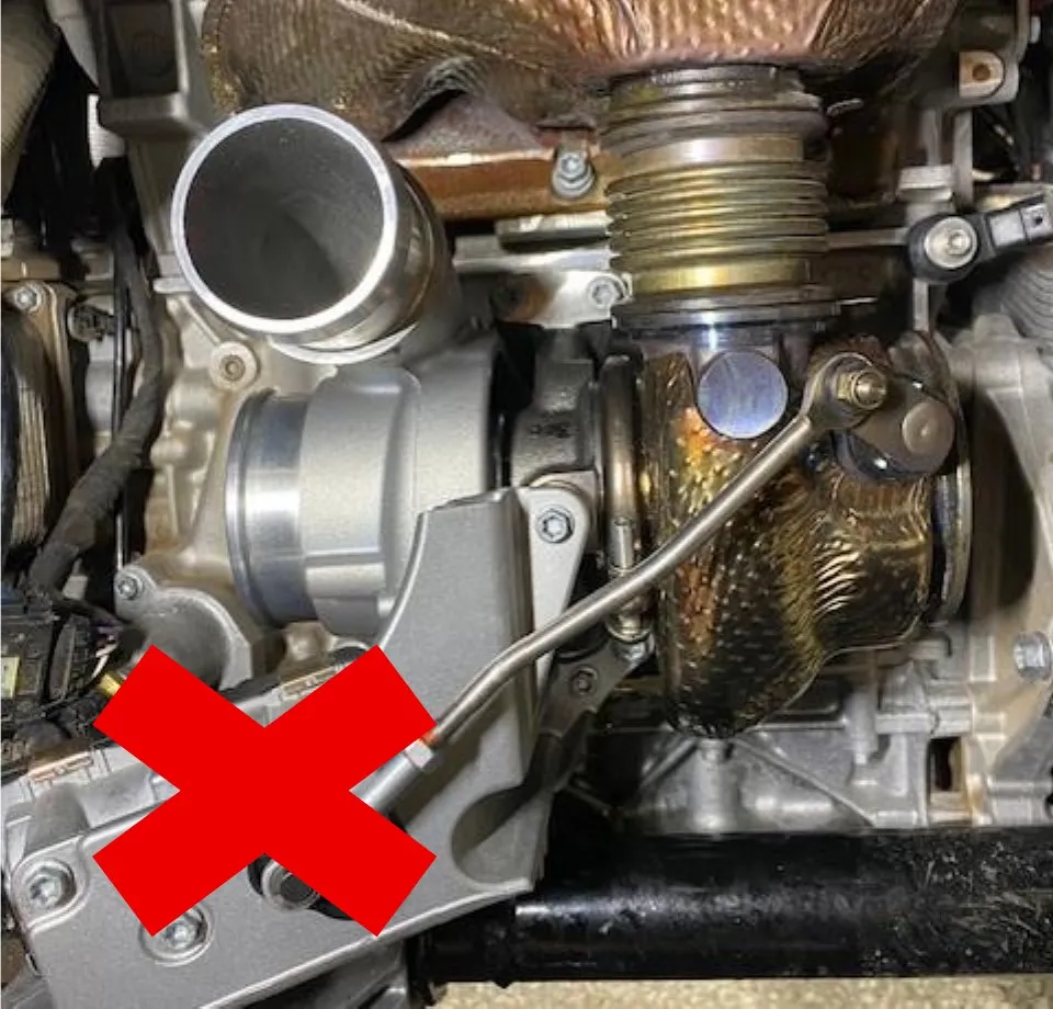
Procedure
Installation
- Step 20
Install the wastegate bracket and supplied (2) M8x16mm screws onto the turbocharger. Install the supplied wastegate rod with sleeve, washer and nut onto the wastegate flap. Install the other side of the wastegate rod to the actuator. You will notice the wastegate flap won’t be closed, this is normal.
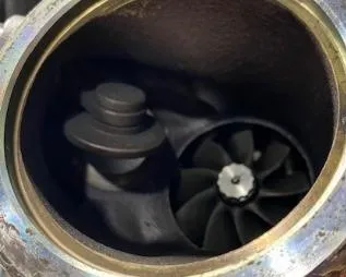
- Step 23
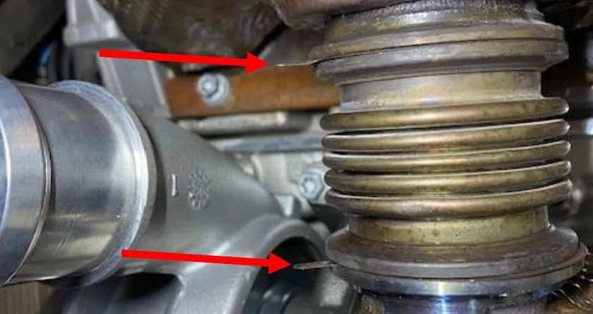
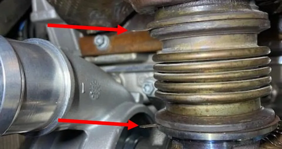
Spin the compensator gaskets so the tabs are facing the wastegate actuator. If not clocked correctly, the V-band clamps will be clocked incorrectly.
- Step 24
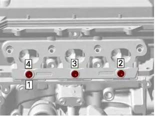
Torque the bottom (3) screws on the clamping plate to 18 ft-lb in sequence.
- Step 25
Install the compensator V-band clamps and hand tighten to now. Make sure the gasket tab is in the opening of the V-band.
- Step 26
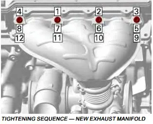
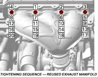
Torque the upper exhaust manifold screws to 18 ft-lb, in sequence. Notice the difference between “NEW” and “USED”.
- Step 27
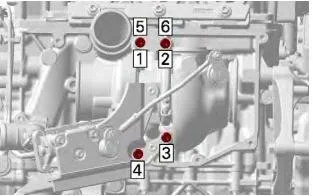
Torque the (4) turbocharger screws to 18 ft-lb in sequence.
- Step 28
Torque the compensator V-band clamps to 80 in-lb.
Procedure
Installation
- Step 27
Remove all the coolant clamps on all hoses.
- Step 28
Reinstall the HFI intake tube.
- Step 29
Reinstall charge tube from intercooler to turbocharger.
- Step 30
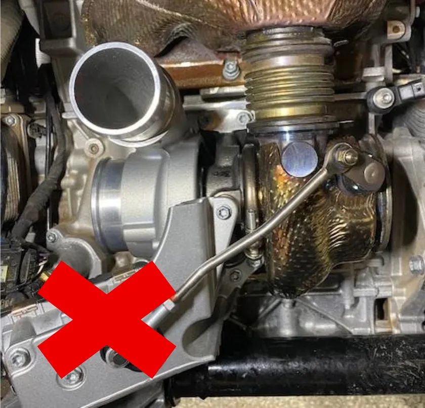
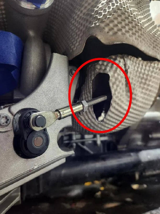
Reinstall exhaust and all heat shields. (see photo below)
 Note
With the new wastegate rod, you will need to notch the lower turbocharger heat shield so the wastegate rod wont get hung up.
- Step 31
Check oil levels, may have to add a little.
- Step 32
Add coolant, heat cycle the engine so thermostat opens to top off coolant.
Procedure
Map Sensor Installation
- Step 1
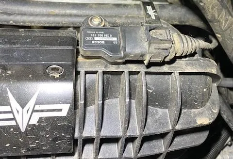
located on the top of the plenum you will find a MAP sensor, remove the electrical connector. With a T-30 socket remove the screw. Remove the OEM MAP sensor. Install dielectric grease on the supplied 4 bar MAP sensor O-ring. Install into the plenum and plug in the electrical connector.
- Step 2
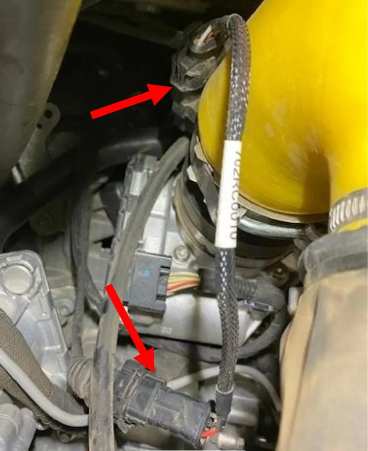
Located on the inside of the throttle body is the second MAP sensor. Remove the charge tube. Unplug the electrical connector, with a T-30 socket remove the screw. Remove the OEM MAP sensor. Install dielectric grease on the supplied 4 bar MAP sensor O-ring. Install the supplied MAP sensor harness to the OEM harness and MAP sensor.
Procedure
Fuel Injector Installation
- Step 1
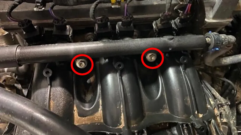
Spray all injector ports and plenum with brake cleaner and compressed air. You do NOT want anything falling into the injector ports. Remove (2) 8mm screws.
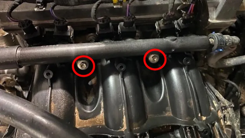
- Step 2
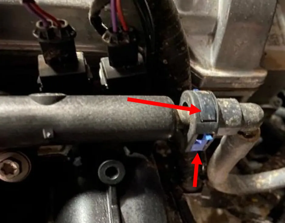
Carefully push down and remove the blue safety clip on the fuel quick connector. DON’T BREAK IT. Press down on the top black connector and remove the fuel hose from the fuel rail.
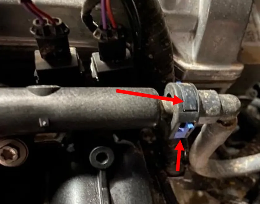
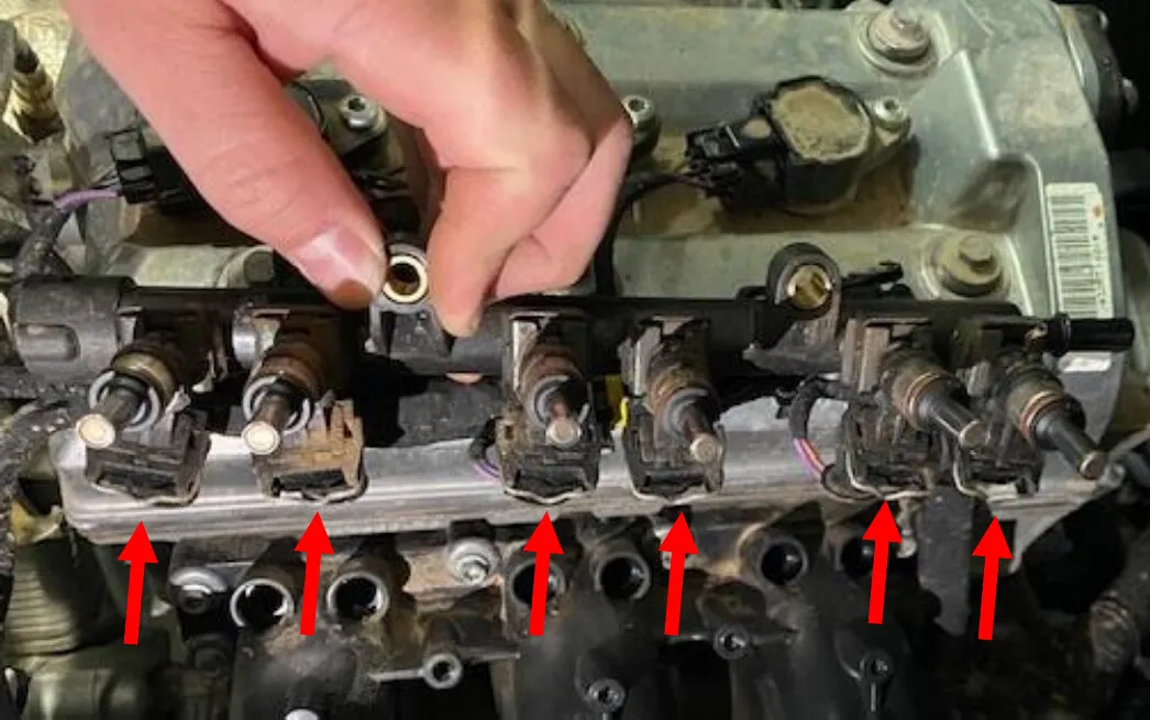
- Step 3
Remove the fuel rail with injectors attached. Flip the fuel rail 180 degrees. Unclip all injector electrical connectors.
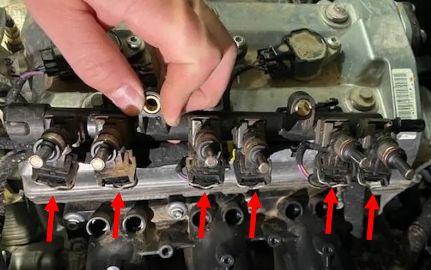
- Step 4
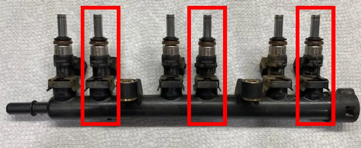
ONLY remove the (3) secondary injector clips. Remove injectors and clean O-rings. Install the (3) supplied 1000cc injectors. Use dielectric grease on the O-rings.
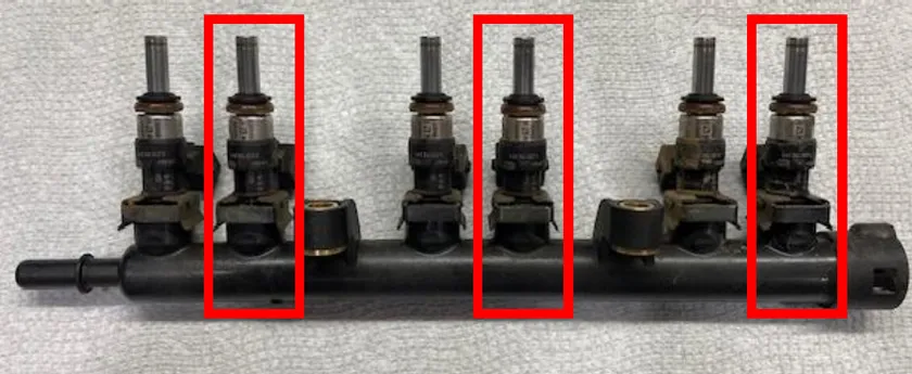
- Step 5
Reinstall all other parts in reverse order. No injector adaptors are needed.
Procedure
Spark Plug Installation
- Step 1
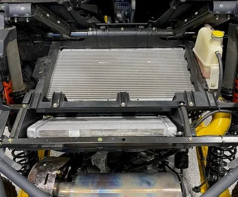
Remove the bed and intercooler / radiator wind dam.
- Step 2
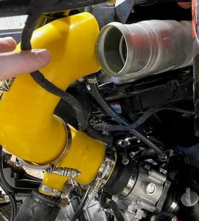
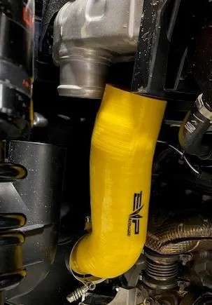
Remove both charge tubes from the intercooler using an 11mm socket.
- Step 3
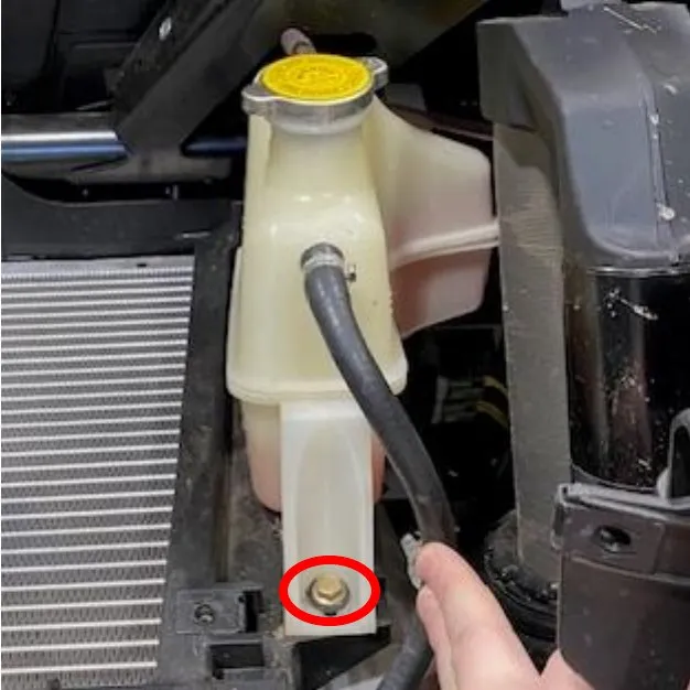
Remove the (1) coolant reservoir mounting screw using a 10mm socket.
- Step 4
Remove the coolant reservoir and bungee it up to the cage.
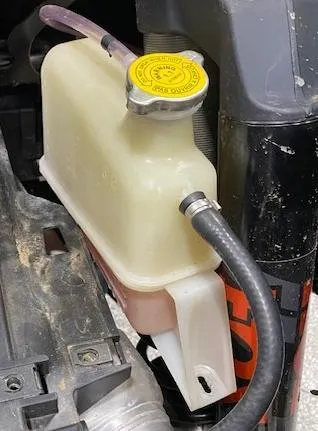
- Step 5
Remove (6) intercooler tray screws using a 10mm socket.
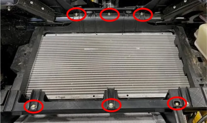
- Step 6
Tilt the back of the intercooler upwards, unplug (2) intercooler fan connectors. Remove the intercooler from the vehicle.
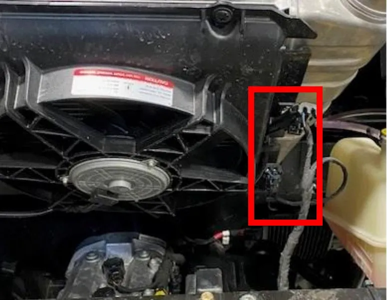
- Step 7
With the intercooler removed you can now access the valve cover. Unplug (3) coil pack connectors, (3) T-30 screws, and remove (3) coils. With a 14mm socket loosen the spark plugs. Use a magnet to remove the plugs.
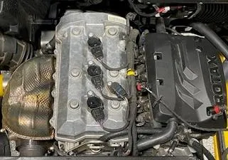
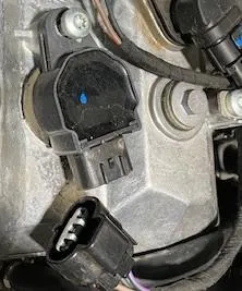
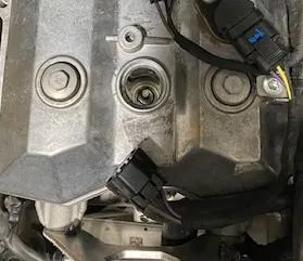
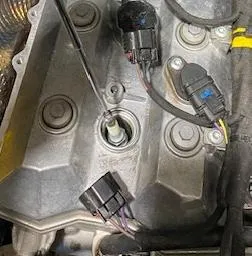
- Step 8
Apply a small amount of anti-seize to the threads of the new plugs. Install the plugs into the head using a magnet. Torque the plugs to 124 in-lb (14 Nm).
- Step 9
Once complete, reinstall vehicle in reverse order.

Emissions notice. This product is exempt from the emission standards and related requirements of 40 C.F.R. § 1051 as provided by 40 C.F.R. § 1051.620, and California law [e.g., vehicle code §§ 27156 and 38391]. This product is sold only for use in connection with EPA certified, purpose-built, nonroad vehicles used solely for closed course, nonroad competition/racing and not used for any recreational purpose or on public highways or right of ways maintained by and open to the public. This product is sold only in connection with machines that do not fall under state and/or federal noise or emission standards/regulations. Purchasers who/that purchase this product represent and warrant that the product is purchased only in connection with EPA-certified, emission-regulations-exempt and noise-regulations-exempt competition/racing vehicles as interpreted under applicable state and/or federal law.
Need technical support?
Submit a ticket with your vehicle and what you're seeing, and our support team will get back to you.
