 BUY NOW, PAY LATER. Starting at 0% APR


Can-Am Maverick R Boost Recirculation Valve (BRV)
Installation instructions for the Maverick R Boost Recirculation Valve (BRV) on the Can-Am Maverick R (SKU 1502010005). Parts, tools, and full procedure.
In the box
Parts and tools
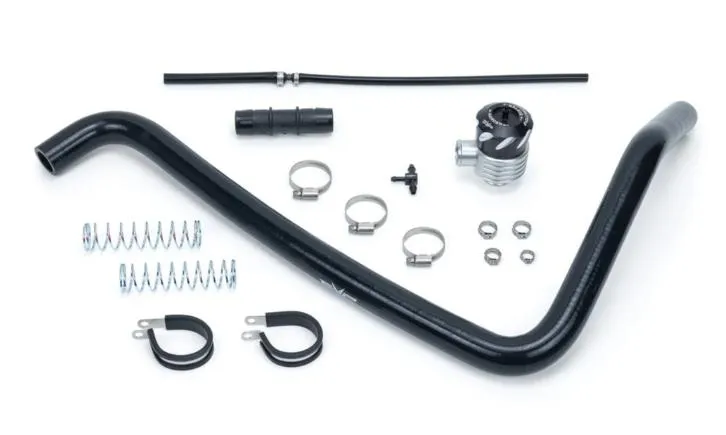
Included parts
- 1Hardware Kit
- 1Intercooler to throttle body silicone
- 1Intercooler to Turbo Silicone
- 1Boost Recirculation Valve (BRV)
Required tools
- Screwdriver(s)
- Pinch Clamp Tool
- 11mm Socket
- Dielectric Grease (optional)
Procedure
Installation
- Step 1
Remove the OEM charge tubes from the intercooler to turbocharger and intercooler to throttle body. In these instructions we already removed them, and the turbocharger intake tube which is NOT needed. We did this for photos.
- Step 2
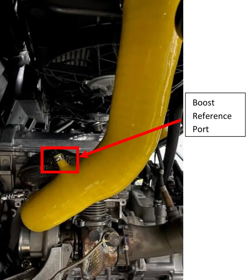
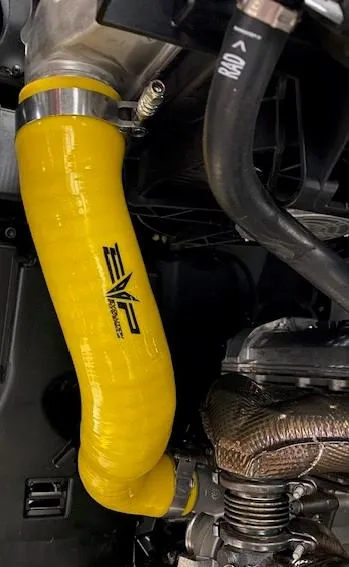
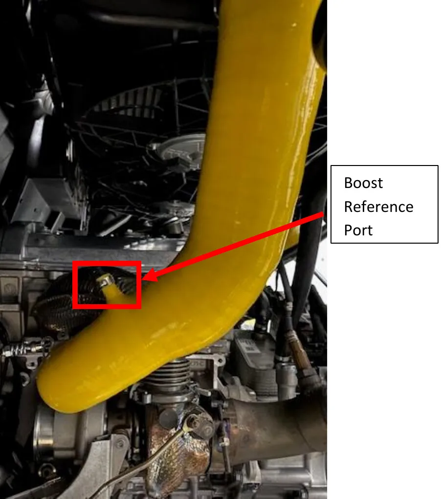
On the turbocharger to intercooler tube, plug the boost reference port with supplied plug and 14.5mm pinch clamp. If you are running a boost gauge or other accessory, you can use this port. Install this tube onto the vehicle. Use supplied 262 & 312 T-Bolt clamps. Use dielectric grease on the silicone if needed.
- Step 3
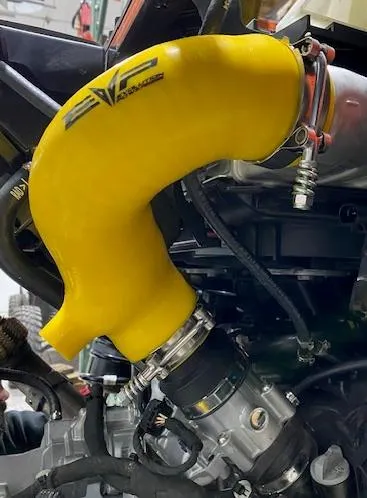
Install the intercooler to throttle body charge tube. Use supplied 312 T-bolt clamps. Use dielectric grease if needed on the silicone. If not running a BOV plug the port with supplied BOV plug and 25-40mm worm drive clamp.
- Step 4
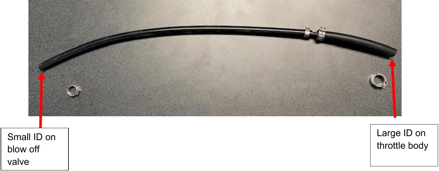
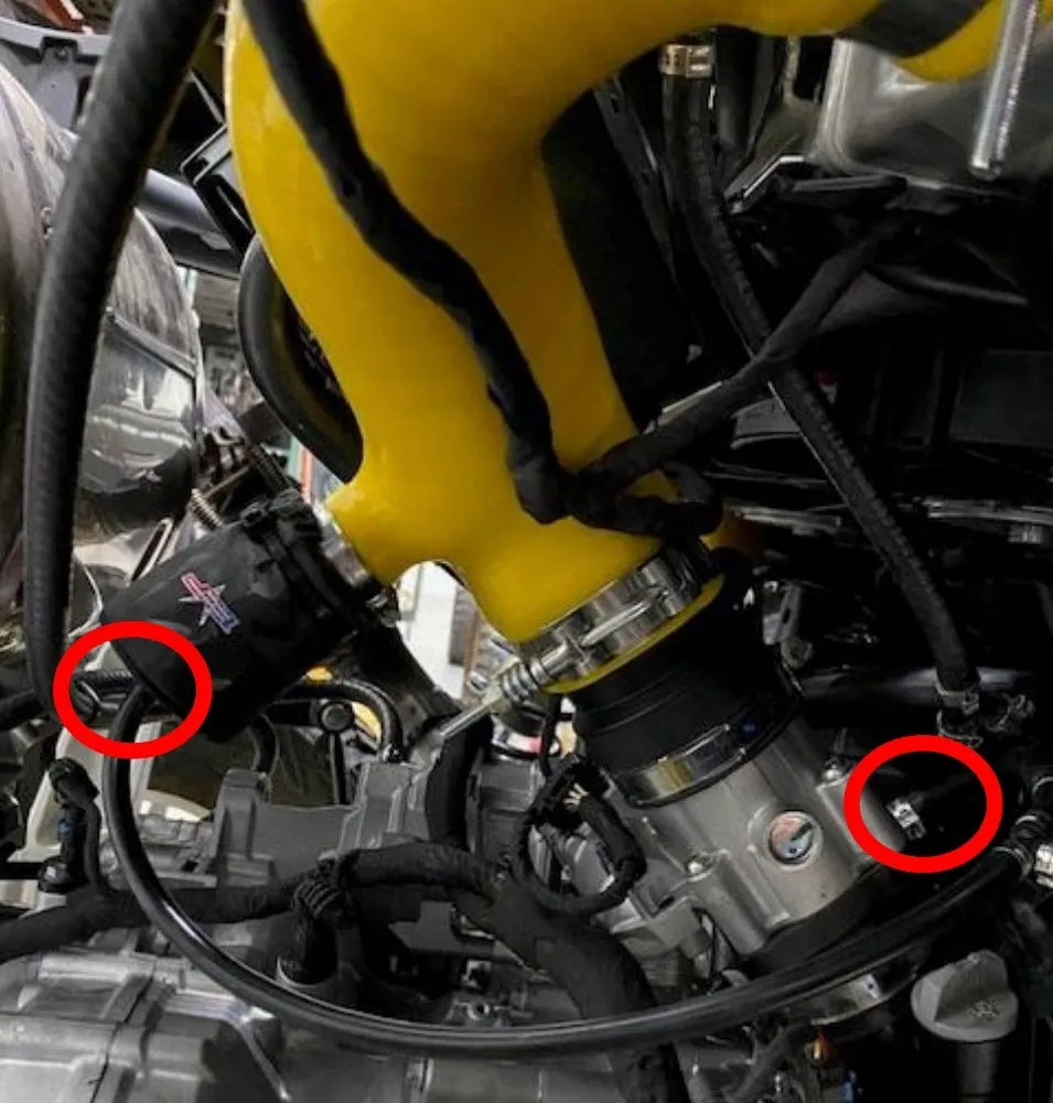
NON-EVAP Cars If installing a Blow Off Valve (BOV), install the prefilter over the BOV and secure with a ziptie. Install the BOV into the charge tube port and secure with a 25-40mm worm drive clamp. Install the larger 6” vacuum line and smaller 14” vacuum line together with supplied fitting and hardware. Install the larger ID vacuum line to the throttle body port and the smaller ID vacuum line to the BOV. EVAP Cars If installing a Blow Off Valve (BOV), install the prefilter over the BOV and secure with a ziptie. Install the BOV into the charge tube port and secure with a 25-40mm worm drive clamp. Remove the self-tightening clamp and canister hose off the throttle body port.


- Step 5
Trim off 1.50-2.0” from the canister hose. Install the short hose to the supplied “T” fitting. Use a 15.7mm pinch clamp and reuse the self-tightening clamp.
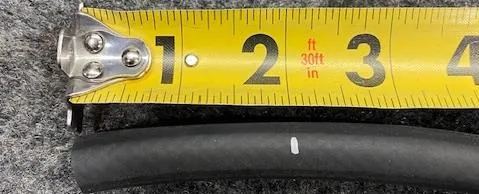
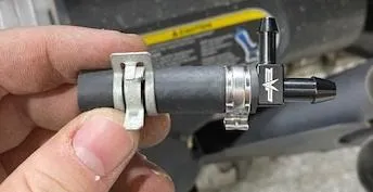
- Step 6
Install the short hose back onto the throttle body port. Reconnect the canister hose to the top port of the “T” fitting. Use supplied 15.7mm pinch clamp.
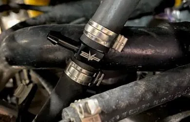
- Step 7
Install the larger 6” vacuum line and smaller 14” vacuum line together with supplied fitting and hardware. Install the larger ID vacuum line to “T” port and use a 13.3mm pinch clamp. Install the smaller ID vacuum line to the BOV, use an 11.3mm pinch clamp.
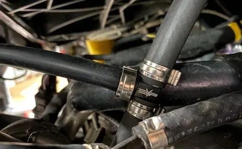
- Step 8
Install the BRV with the port facing the engine. Install with a 25-40mm worm drive clamp.

- Step 9
Install the BRV hose as shown. The 90 Degree bend will connect to the valve.
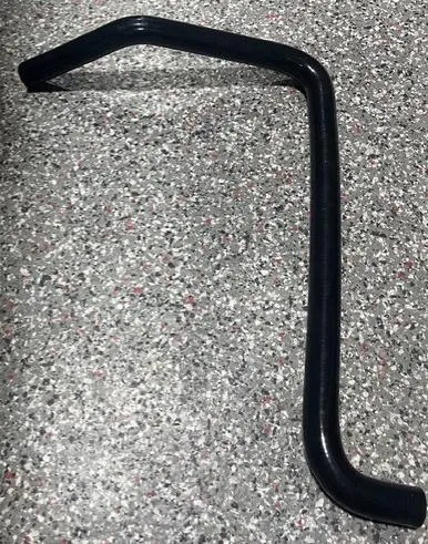
- Step 10
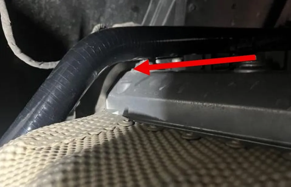
Route the hose across the top of the plenum to the firewall. Across the top of the valve cover and towards the HFI silicone duct.
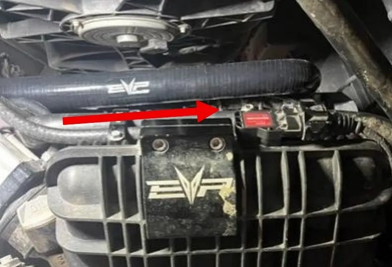

- Step 11
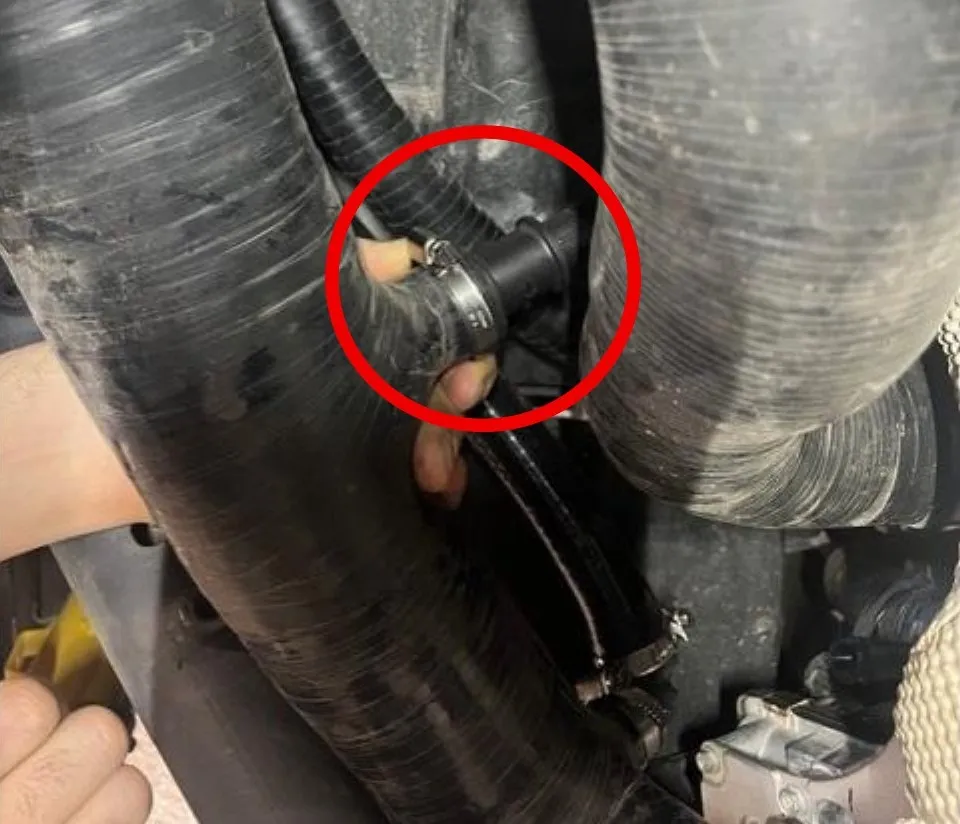
Locate the 1.0” port on the HFI duct. Remove the plug and install the 1.0” barb. Fasten down with 25-40mm worm drive.
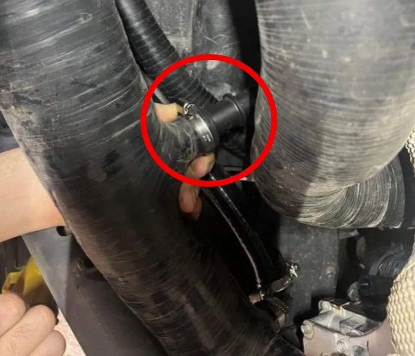
- Step 12
Connect the BRV hose to the 1.0” barb. Tighten down with 25-40mm worm drive.
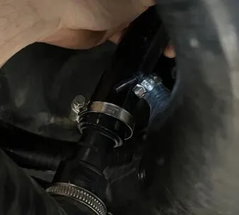
- Step 13
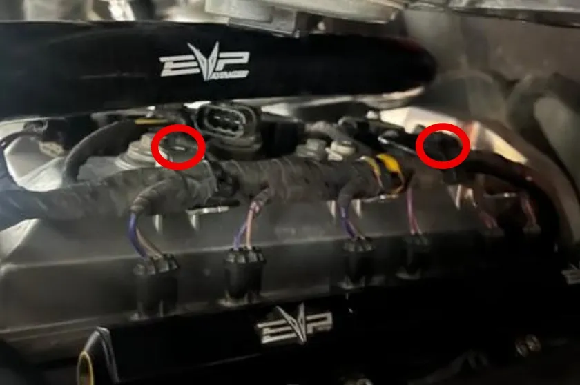
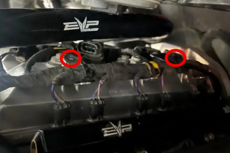
Locate (2) T-30 Torx screws holding the engine harness to the valve cover, remove these screws.
- Step 14
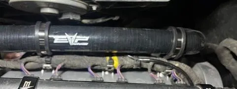
Install (2) supplied clamps around the BRV hose, reinstall the torx screws to the valve cover.

Need technical support?
Submit a ticket with your vehicle and what you're seeing, and our support team will get back to you.
