 BUY NOW, PAY LATER. Starting at 0% APR


This is a high-performance upgrade! Although we have gone through great lengths to build safety into the upgrade turbo system, the fact is installing any upgrade / turbo system requires care in both operation and installation. Poor fuel, improper setup or any number of things that are done incorrectly can damage your engine!
Defender HD11 Turbocharger 200 Upgrade System
Defender HD11 Turbocharger 200 Upgrade System
Before you start
Note
Expect 24–48-hour delay from the time you request a tune to when the file is enabled. Please create your CodeShooter account before starting the project.
Note
We recommend an oil change before initial start up
- You have likely voided the sound and exhaust emission standards of your country if applicable.
- This upgrade is intended for OFFROAD and RACING use only.
- This is a performance upgrade which will VOID your engine warranty especially if installed incorrectly or operated without regard to your instruments.
- The fuel requirements must be adhered to. Poor fuel can destroy an engine in seconds.
- Evolution Powersports bears no responsibility for damage caused to your vehicle by the installation of EVP products. The warranty on big turbo kits is 30 days from the date of purchase. Evolution Powersports, at its discretion will determine whether a part meets the warranty requirements. In no case is there any warranty from EVP for your vehicle or vehicles drivetrain. Although we have been careful to supply you with the highest quality parts possible, we assume no liability for damage to the vehicle or personal injury from installing or using any of our products.
- The installation of this kit is technical and mechanical in nature with many opportunities to make mistakes – mistakes that can be very costly. If you are not qualified to install this kit, bring your vehicle to one of our qualified installation centers to do the installation.
- This kit will make your vehicle faster, climb higher and accelerate more quickly and take a longer distance to brake than a stock tuned vehicle. If you are not capable of controlling the vehicle with the added performance, do not install the kit.
- High boost is hard on spark plugs – they must be changed frequently. If you experience misfire issues – Gap and replace the spark plugs.
- Do not ever allow a child or an unqualified driver to operate this vehicle.
| Level | Tunes | Max Boost (psi) | Spark Plug Gap | Spring | Waste Gate (psi) | Wheel HP |
|---|---|---|---|---|---|---|
| Stage 1 | 91 | 6 | .016 - .018 | EVP | 4.0 | 120 WHP |
| Stage 2 | 100 | 11 | .016 - .018 | EVP | 4.0 | 145 WHP |
| Stage 3 | E85 | 15 | .016 - .018 | EVP | 4.0 | 165 WHP |
Recommended Parts (Sold Separately)
- Defender BOV Kit (100FC0165)
- Defender Catch Can Kit
- Defender BRV Kit
- Clutch Kit or TAPP Clutch (Operating RPM 7300-7500 for 91octane)
In the box
Parts and tools
Parts Included in Defender DT-200 Turbo Upgrade System
| 2752010077 | Defender HD11 Turbocharger Assembly |
| 2042010011 | Defender HD11 Turbocharger Downpipe Assembly |
| 2772010001 | Defender HD11 Turbocharger Installation Assembly |
| 2772010002 | Defender HD11 Oil Pump Assembly |
| 1532010015 | Defender HD11 Charge Tube Assembly |
| 1552010006 | Defender HD11 Intercooler Assembly |
| 1512010002 | Defender HD11 Turbocharger Boost Control Solenoid Assembly |
| 3002010007 | Defender Turbocharger Boost Control Wire Harness Assembly |
| 2772010003 | Defender HD11 Voltage Regulator Relocation Assembly |
Parts Included Defender Stage 1 Turbo Install Kit
| 2512010001 | X3 1000 Injectors, Set Of 3 | 1 |
| 2521010005 | 2020+ X3 Turbo RR 1000cc Fuel Injector Adapter Kit, Set of 3 | 1 |
| 3552010001 | X3 Spark Plug Set of 3 | 1 |
| 3002010020 | Defender HD11 Intercooler & Oil Pump Harness, Assembly | |
| 1752010004 | 2018+ Defender HD10 Airbox Assembly | 1 |
| 1791010018 | Defender HD11 Airbox Bracket | 1 |
| 2771010015 | Defender HD11 Turbocharger & Muffler Plate | 1 |
| 6001990229 | M8-1.25 x 20 Flanged Button Head Screw, Black Stainless | 9 |
| 1531990008 | 2.0" Black Silicone Cap | 1 |
| 6001990160 | 40/60 12mm Wide Worm Drive | 1 |
| 1012010207 | Defender HD11 CodeShooter Power Flash Stage Turbo 91, 100, E85 | 1 |
| 6001990317 | M8 x 1.25 Distorted Locknut | 7 |
| 6001990274 | M10-1.50 x 20mm Socket Head Screw, Stainless | 1 |
| 6001990551 | 1.0" Silicone Rubber Isolator with M8 Stud | 1 |
| 6001990174 | M8 x 1.25 Serrated Flange Nut | 1 |
| 6001990175 | M8 x 1.25 x 20mm Flanged Hex Screw | 1 |
| 6001020041 | M8 x 24mm OD Fender Washer, Black Stainless | 4 |
| 3631990001 | Bosch 4 Bar MAP Sensor | 1 |
| 6001990553 | 5/16” Push Pin Retainer, Black | 1 |
Procedure
Installation
- Step 1
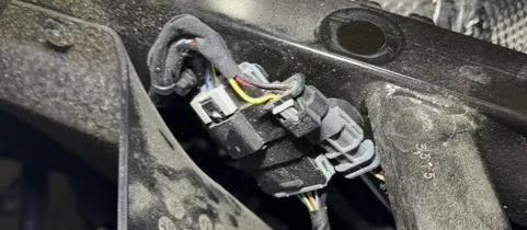
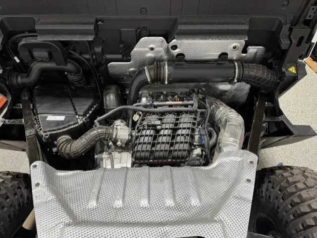
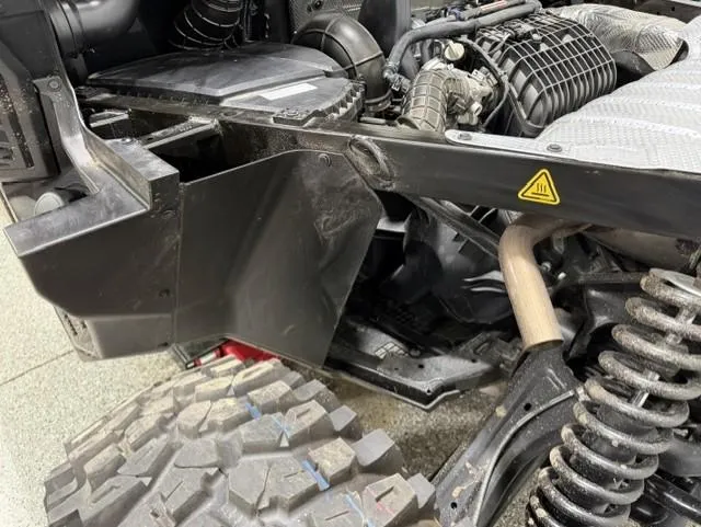
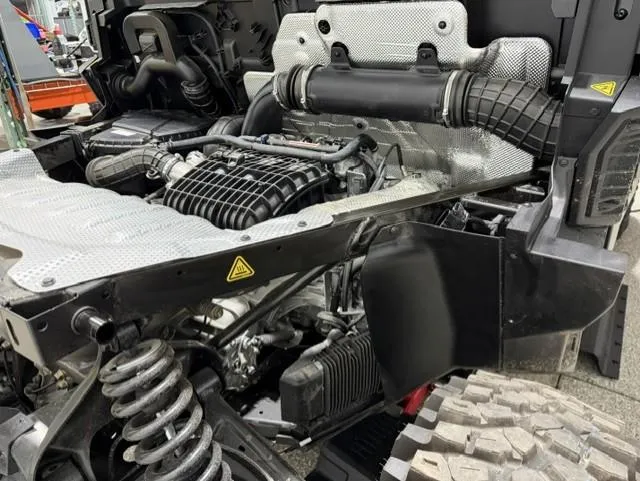
Remove the bed, tip up the bed and remove the shock and (2) pins. Disconnect the electrical connector for the rear taillights located on the passenger side of the bed frame. Remove (4) 14mm nuts and (2) plastic bed mounts. Lift bed off.
- Step 2
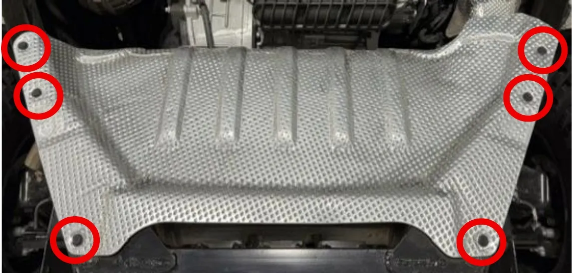
Remove the (6) push darts on the muffler heat shield. Remove heat shield.
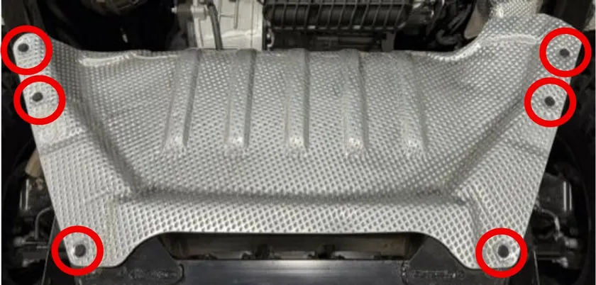
- Step 3
Remove the muffler. (2) 13mm screws and exhaust springs between the downpipe and muffler. Remove exhaust donut. Remove (2) 13mm bolts, washers, springs and nuts mounted underneath the muffler. Located on each side of the muffler. Remove (1) 13mm bolt on the front side of the muffler. Slide the muffler and plate forward to unlock the tabs.
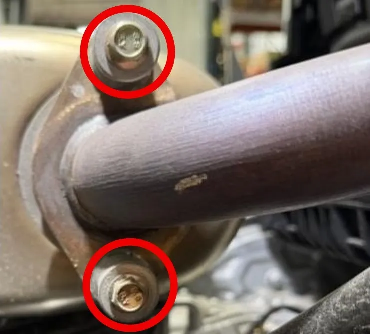
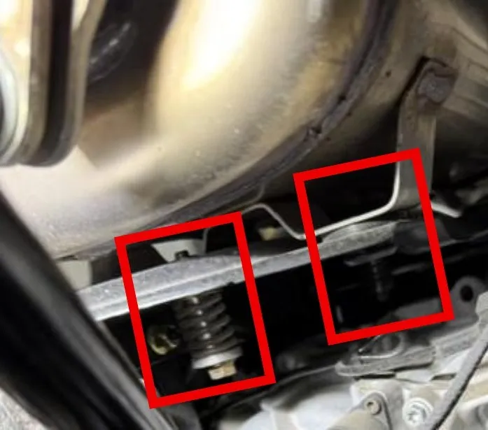
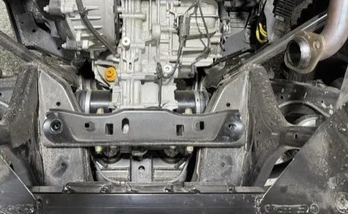
- Step 4
Remove (2) exhaust springs holding the downpipe to the head pipe. It may help to loosen the heat shield worm drive clamps, but not needed. Remove exhaust donut.
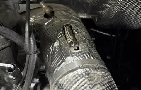
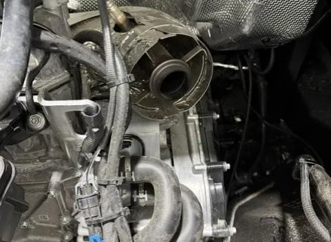
- Step 5
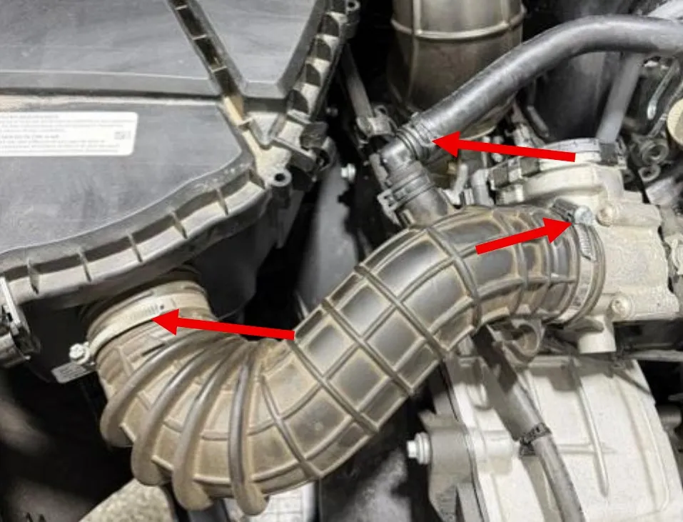
Remove the intake tube. Remove (1) self-tightening clamp from the valve cover hose. Loosen (2) worm drive clamps.
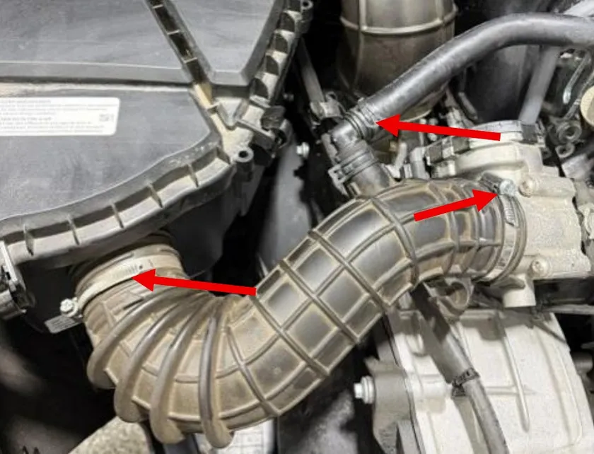
- Step 6
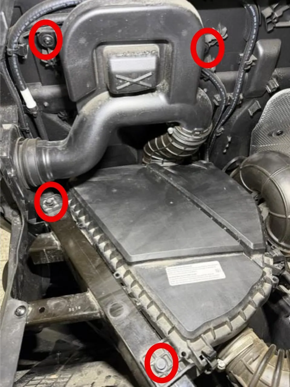
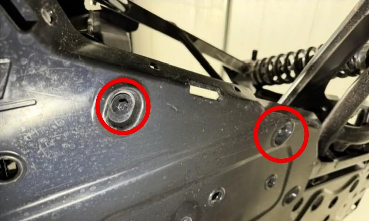
Remove airbox and fresh air intake. Remove (2) T-20 screws from the fresh air intake located on the firewall. Remove (2) push darts located on the frame rail.
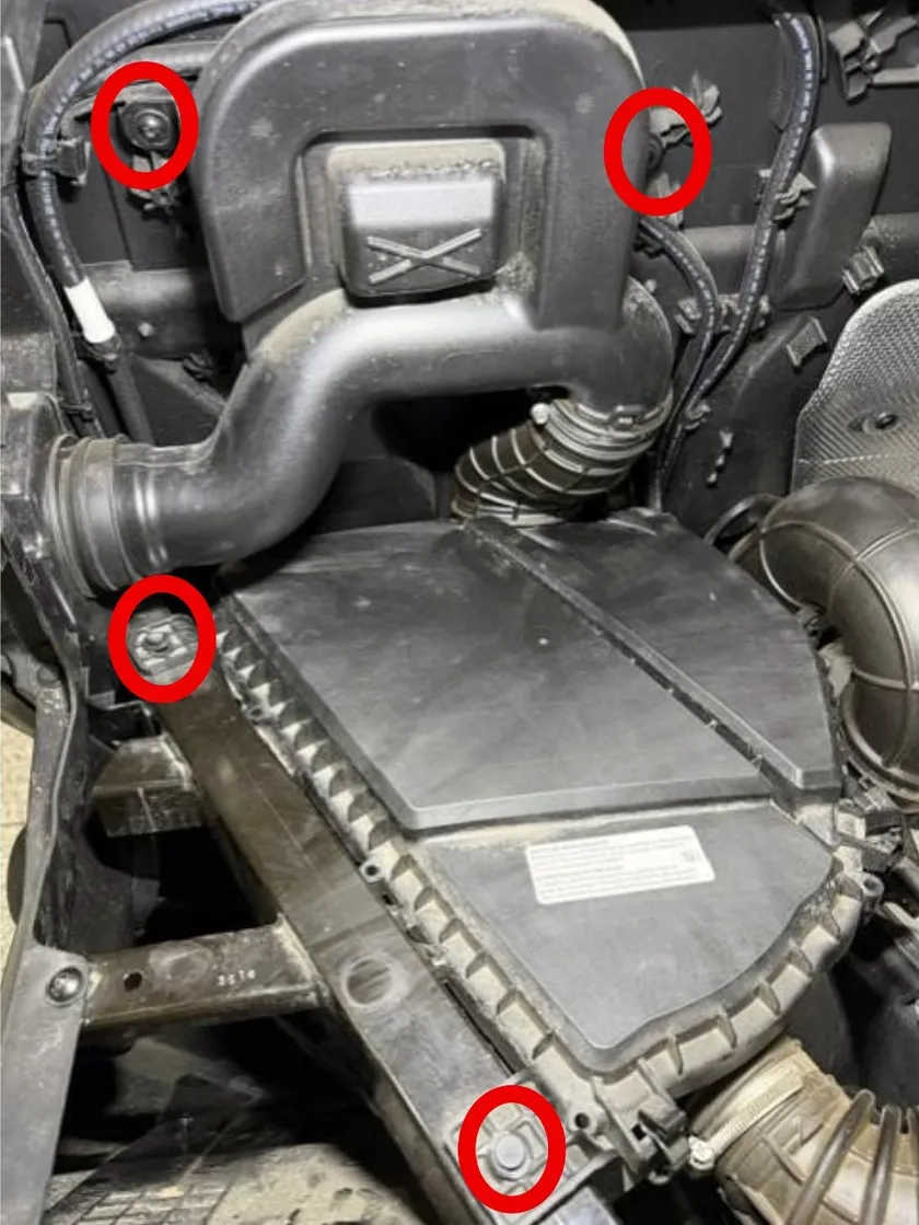

- Step 7
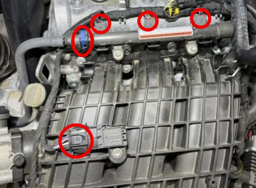
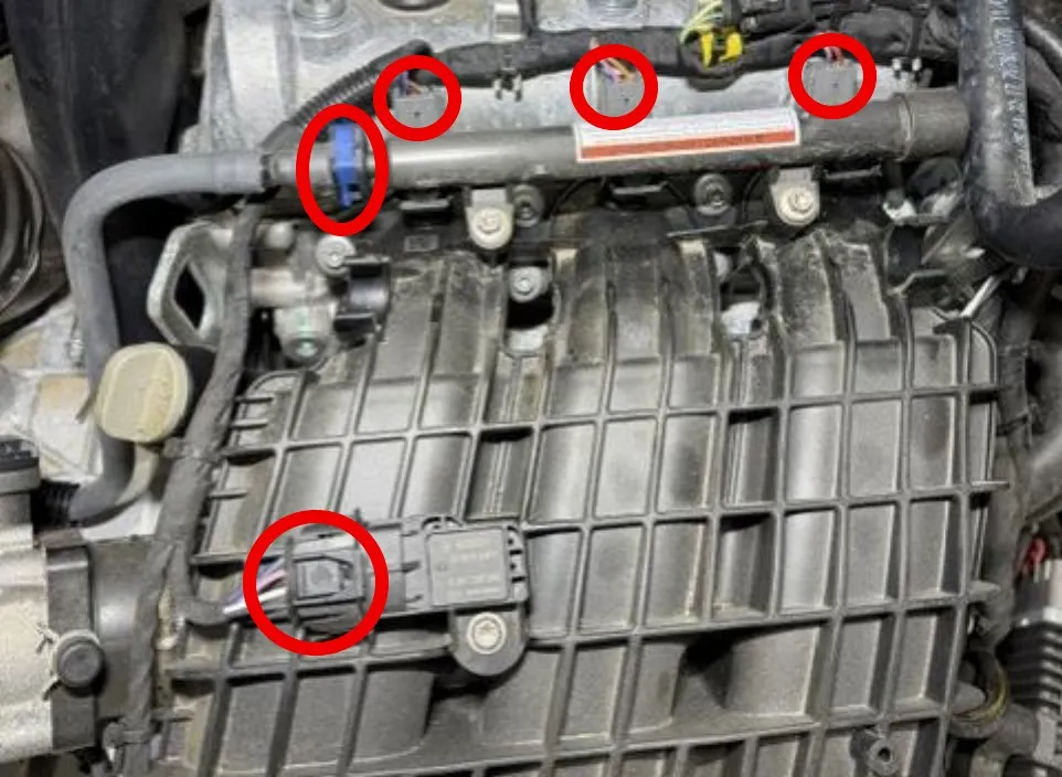
Remove the intake manifold. Remove the harness connector from the throttle body, pull the red tab out and push down on the locking black tab. Remove the map sensor harness, fuel line from the rail. Pull the blue tab upwards and push the black locking tab underneath. Disconnect the injector connectors. Cut any zip ties holding the harness to the plenum and throttle body.

- Step 8
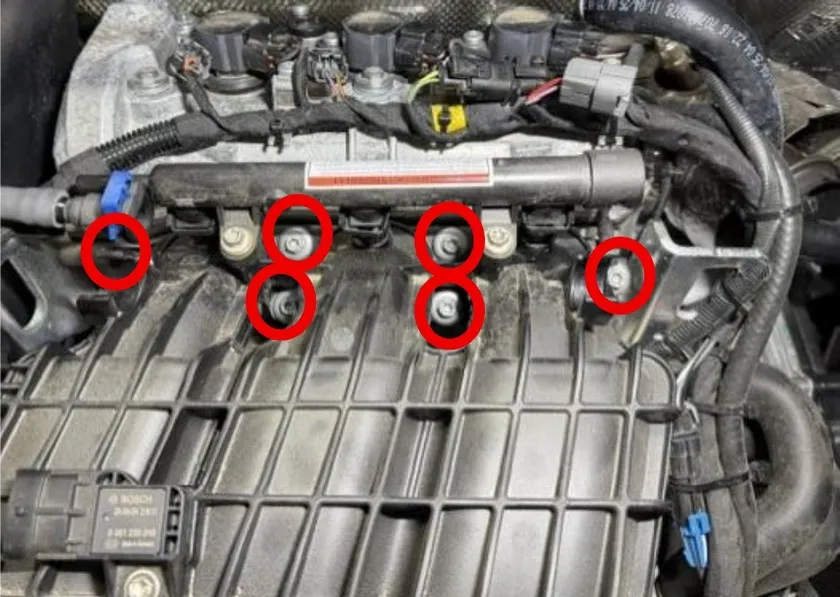
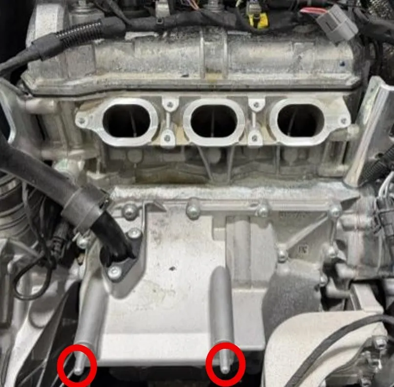
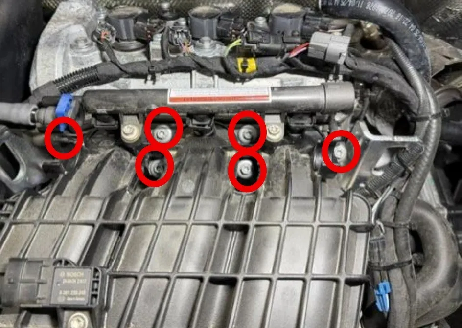
Remove (6) T-30 manifold screws. The far-right screw has a ground terminal ring on it. Carefully pull the intake manifold backwards 2.0” before you go upward. There are two rubber grommets underneath.
- Step 9
Remove (3) coil packs, remove (3) T-30 screws holding the coil packs down, remove (3) connectors.

- Step 10
With a 14mm socket, remove the (3) spark plugs. Use a magnet to pull the spark plugs out without damaging them.
- Step 11
Install the supplied (3) spark plugs. Lower into the head with a magnet and torque to specification. 9.5 ft-lb.
- Step 12
Reinstall the coil packs, T-30 screws, and electrical connections.
- Step 13
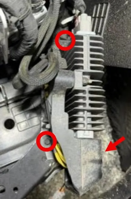
Locate the voltage regulator on the passenger side of the vehicle. Remove (3) 10mm screws mounting it to the frame.
- Step 14
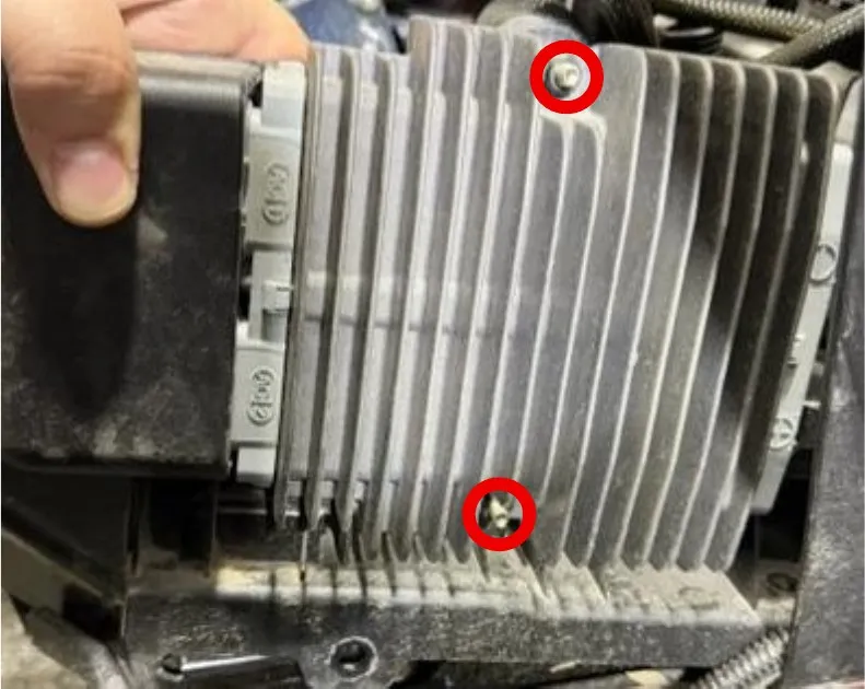
Remove the two M6 bolts and locknuts holding the bracket to the voltage regulator.
- Step 15
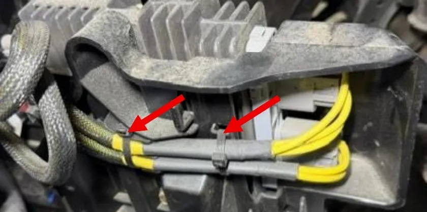
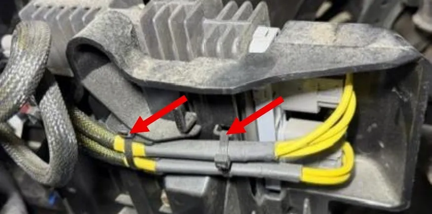
On the backside of the voltage regulator bracket, cut all the zip ties holding the yellow wires together.
- Step 16
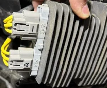
Mark both yellow wire grey connectors 1 & 2. Unplug both connectors.
- Step 17
Locate the new voltage regulator bracket and hardware.

- Step 18
Mount the new black bracket to the voltage regulator. Reuse OEM hardware.

- Step 19
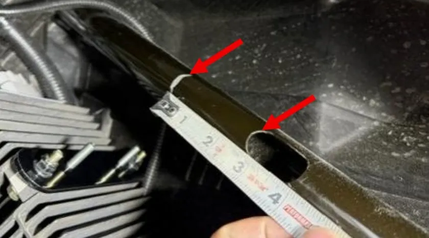
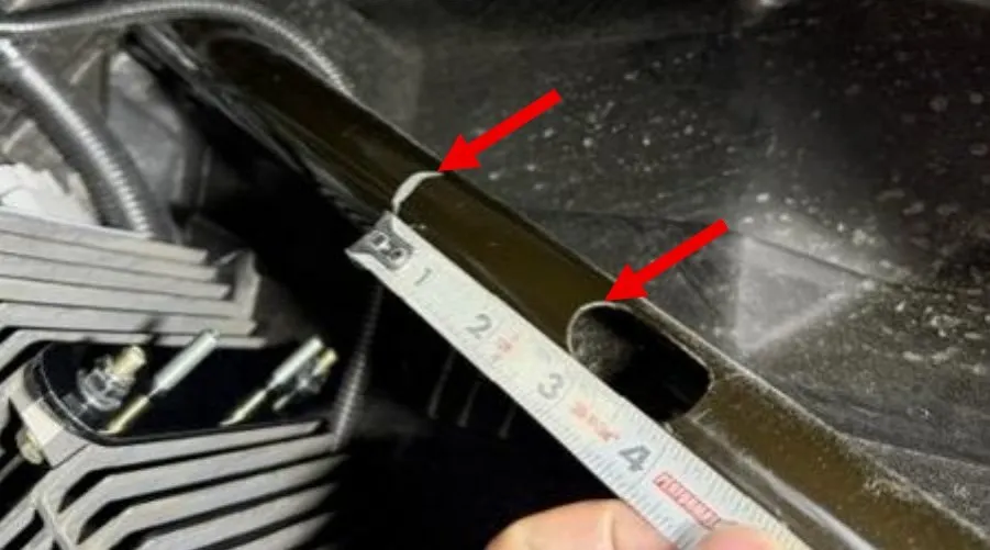
Locate the rear wheel well frame rail. Measure from the factory hole 3.0” down the rail (also towards the firewall) and mark with a silver sharpie.
- Step 20
Install the rubber strip with adhesive on the back side. Install the rubber on the outside of the frame rail as shown in the photo. Install the billet half moon bracket over the rubber.

- Step 21
Install the voltage regulator bracket with M6 studs to the billet half-moon. Fasten down with supplied M6 locknuts. Only tighten enough so the bracket cannot slide or turn. The brackets DO NOT NEED to touch. Reconnect grey connectors and zip tie excess yellow wires together.
- Step 22
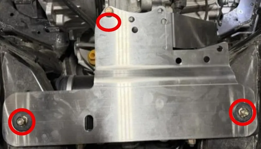
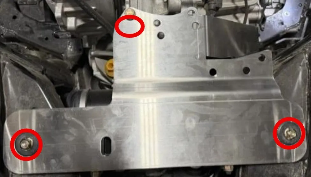
Install the turbocharger and muffler mounting plate where the OEM muffler was located. Reuse the OEM hardware. Apply red Loctite to the upper M8 bolt. Leave this hardware loose for now.
- Step 23
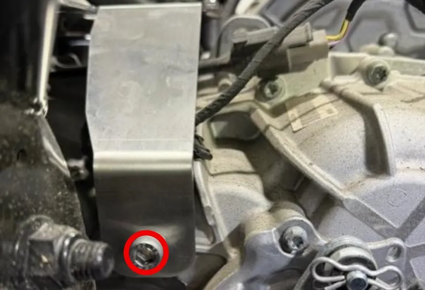
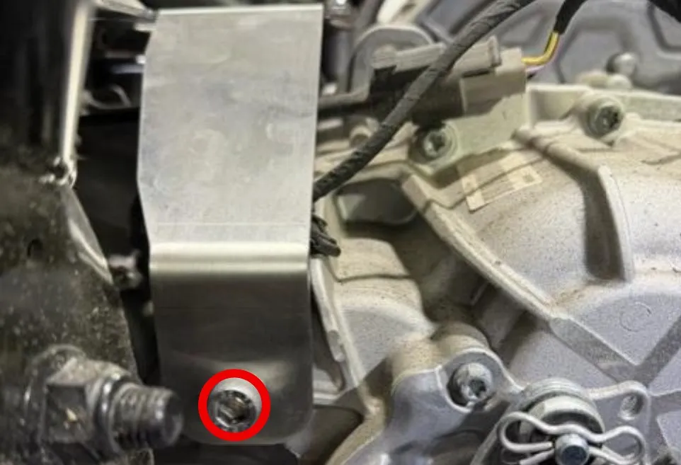
Install supplied M10 socket cap screw into the lower bracket located on the passenger side of the vehicle.
- Step 24
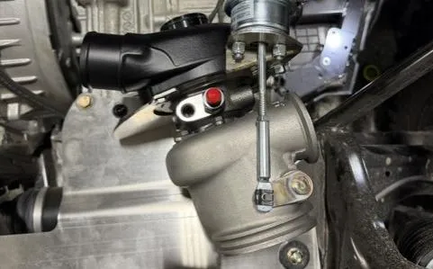
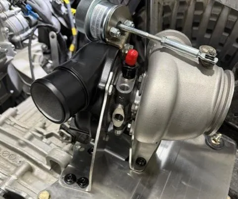
Install the turbocharger to the bracket. Install (7) M8 Allen screws from top and (7) M8 distorted nuts from the bottom. It is best to use a ball nose Allen and open-end wrench. Leave this hardware loose enough to adjust the turbocharger.
- Step 25
Install the stainless-steel exhaust gasket onto the head pipe. You may need to slightly prebend the (3) inner tabs. Once installed, you can cut off the outer tab.
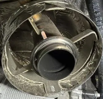
- Step 26
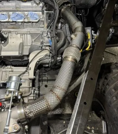
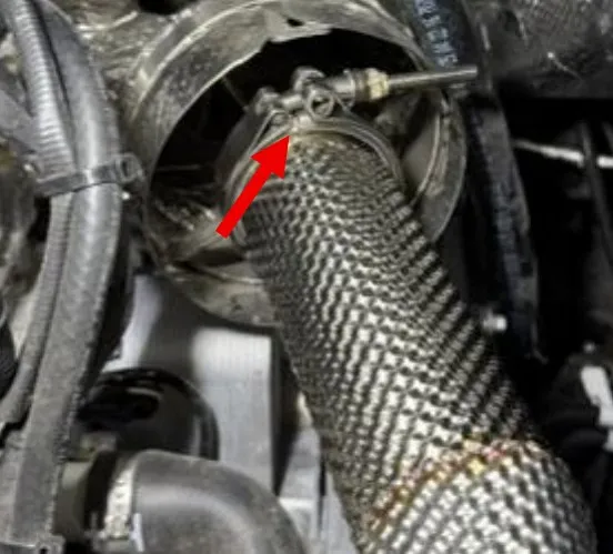
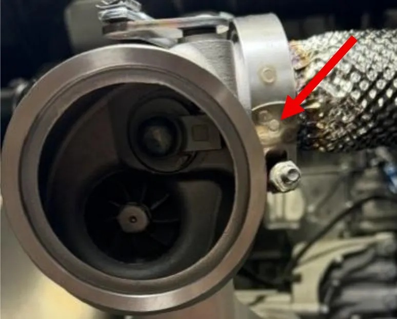
Install the downpipe between the head pipe and turbocharger inlet. You MUST use the 2.0” V-band that came with the downpipe on the connection to the head pipe. Use the 2.0” V-band that came with the turbocharger on the turbocharger inlet. There is a difference between these two clamps!
- Step 27
Apply anti-seize to both V-band threads. Make sure the flanges are seated correctly. Start from the head pipe connection back to the turbocharger when tightening. DO NOT overtighten the clamps. Torque around 10 ft-lb.
- Step 28
Locate the exhaust mount isolator and hardware. (1) isolator, (1) M8 flange nut, (1) M8 flange bolt, (4) M8 washers.
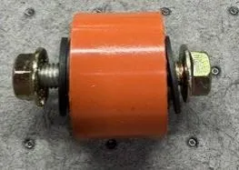
- Step 29
Install the M8 bolt and washer underneath the turbocharger & muffler mounting plate in the slotted hole. Install (1) M8 washer onto the bolt.
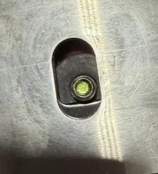
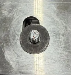
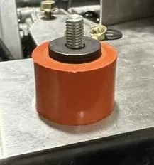
- Step 30
Install the isolator onto the M8 screw and tighten by hand. Install (1) M8 washers onto the stud of the isolator.
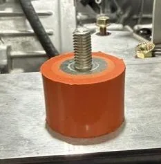
- Step 31
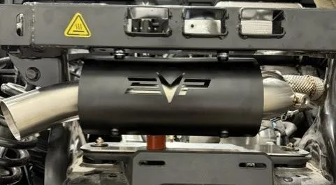
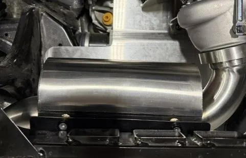
Install the muffler onto the turbocharger discharge V-band and isolator. Install the supplied V-band loosely and align the muffler mount to the isolator. Install an M8 washer and nut on the isolator. Tighten the V-band to 10 ft-lb and use anti-seize.
- Step 32
Go through and finish tightening the turbocharger & muffler plate, turbocharger, double check all V-bands are tight.
- Step 33
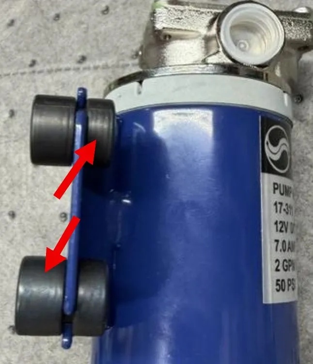
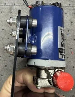
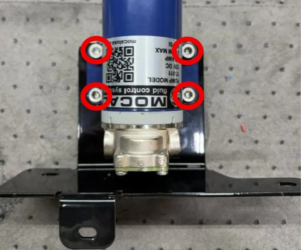
Locate the oil pump. Install the rubber grommets as shown in the photo below. Large portion towards the back of the pump, and the smaller portion towards the pump.
- Step 34
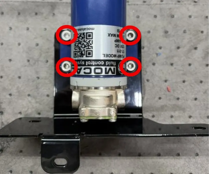
Install the pump to the pump bracket. The pump will be mounted upside down. Fasten down with (4) supplied M8 socket cap screws and (4) locknut. Do not overtighten, just snug as there are (4) rubber grommets.
- Step 35
Install the supplied 8an to ORB fittings onto the pump. Remove the clear caps and thread fittings into the pump. Make sure each fitting has O-rings on the pump side. Tighten down.

- Step 36
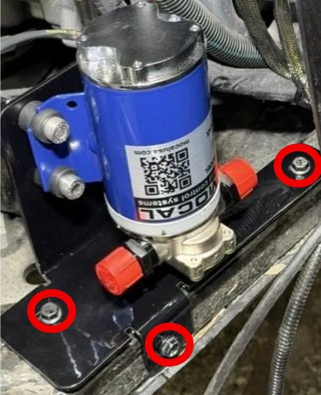
Mount the oil pump into the vehicle where the voltage regulator was originally. Reuse (3) OEM M6 screws.
- Step 37
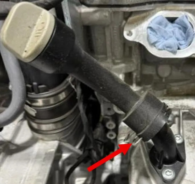
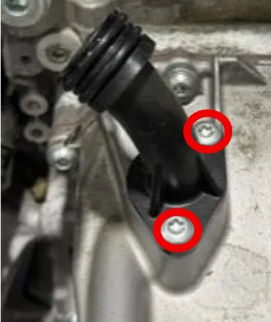
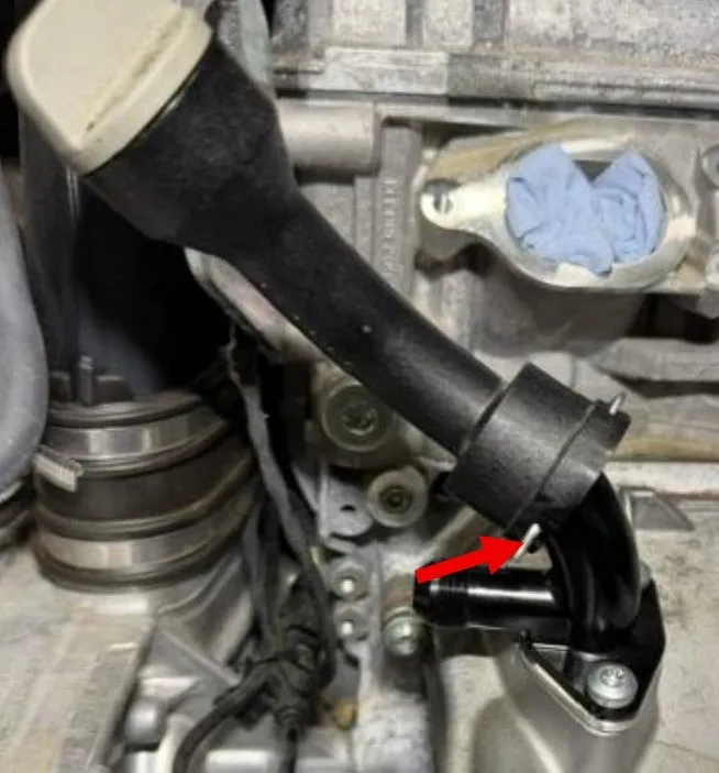
Locate the oil dip stick. Remove the oil dip stick, remove the C-clip holding the upper dip stick on. Remove upper dip stick. Remove (2) T-30 screws holding the lower dip stick in. Grab a rag and remove the lower dip stick from the case.
- Step 38
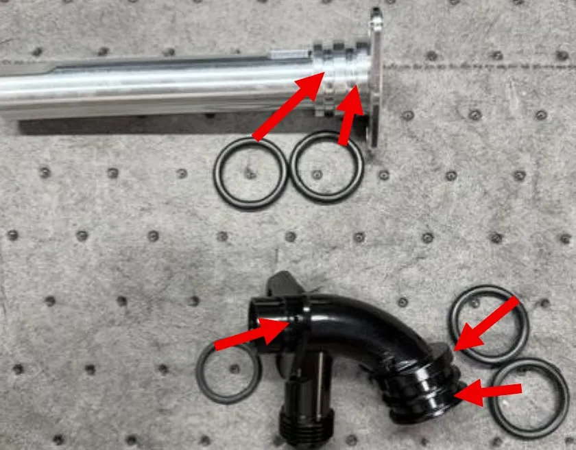
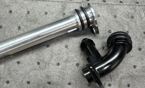
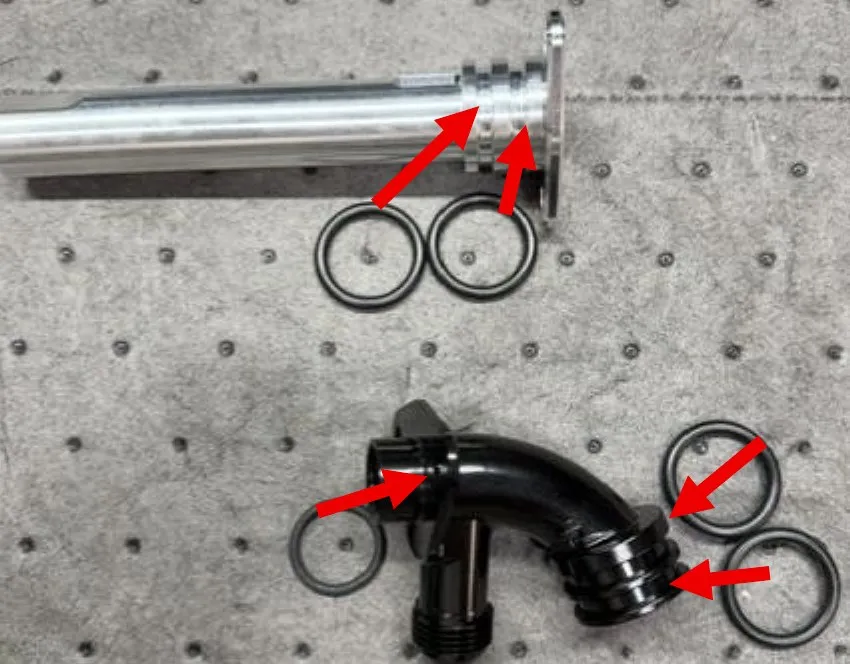
Locate the new dip stick assembly. (4) larger O-rings and (1) smaller O-ring, (1) upper and lower dip stick. Install the O-rings into the O-ring grooves on the billet dip stick pieces. Use oil or dielectric grease.
- Step 39
Install the lower dip stick into the case. Push into place so the O-rings seat. Install the new middle section with AN fitting on top of the lower portion. Install (2) OEM T-30 screws. Make sure the holes are aligned correctly.
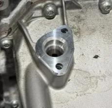

- Step 40
Align the tab on the upper dip stick tube to the middle section. Once fully seated, install the C-clip. Reinstall the dip stick.
- Step 41
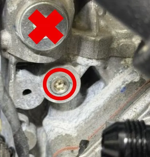
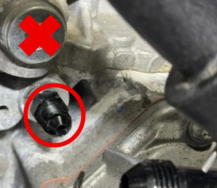
Locate the 1/8” NPT plug behind the dip stick tube. Remove the plug and install the supplied 1/8” NPT to 4AN fitting. This is NPT so it will not bottom out, tighten until snug. If you bottom the fitting out you can ruin the fitting.
- Step 42
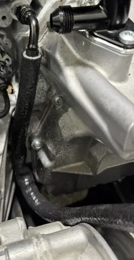
Locate the oil feed line. Install the 1/2" fire sleeve over the line. Install the oil feed line to the 4AN fitting on the head route it over to the turbocharger. The hose will lay in a channel off the transmission.
- Step 43
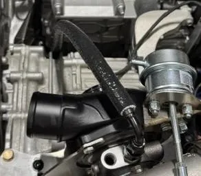
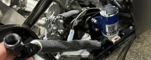
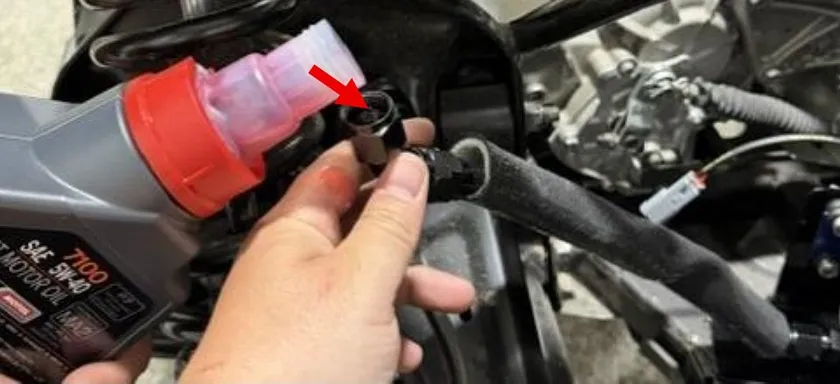
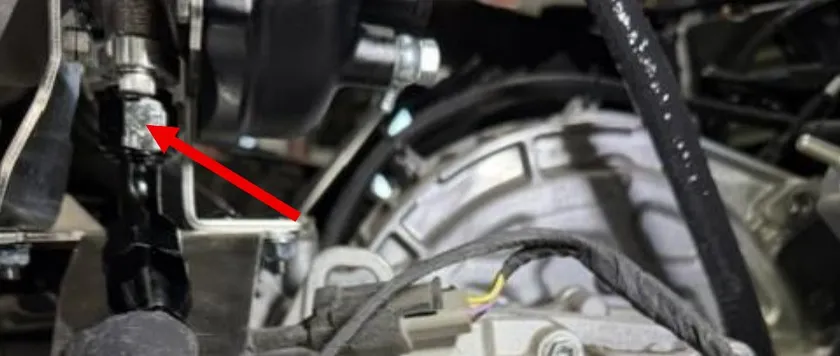
Install fire sleeve over the 17” 8AN hose. Install this hose onto the pump. MUST POUR 3OZ OF OIL DOWN THE HOSE. THE PUMP MUST BE PRE-OILED. Once pre-oiled, connect the other side of the hose to the turbocharger drain plate.
- Step 44
Locate the longer 8AN hose. Install fire sleeve on the end going back towards the engine. Install the other end on the pump exit. Route the hose up over the pump, underneath the transmission mount and up to the middle section of the dip stick tube.
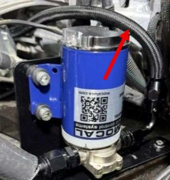
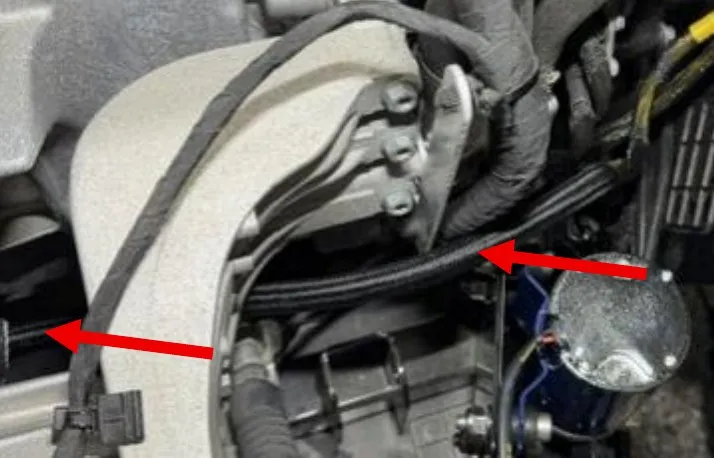
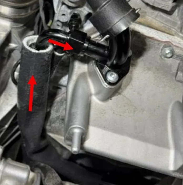
- Step 45
Locate the intake manifold on a bench. Remove the T-30 screw holding the MAP sensor in. Remove the OEM MAP sensor and install the new sensor. Apply dielectric grease on the O-ring. Remove the (2) T-25 screws holding the fuel rail on. Remove the rail with injectors attached, pour out the remaining fuel in the rail.
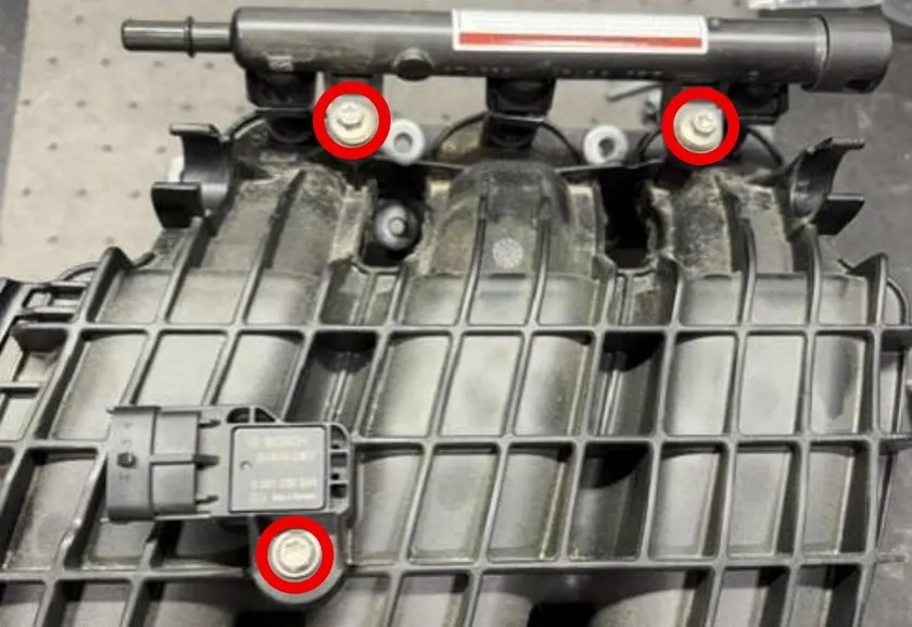
- Step 46
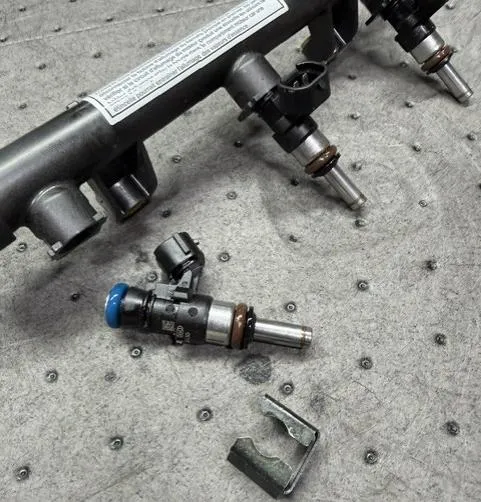
Remove the injector clips. Remove the injectors and put into a plastic bag. Apply dielectric grease to the new injector O-ring and install into the fuel rail. Make sure the injectors are clocked correctly. Reinstall the safety clip.
- Step 47
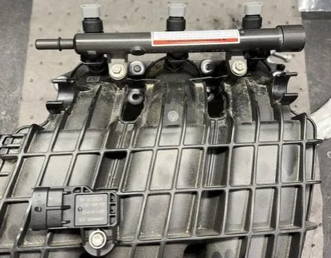
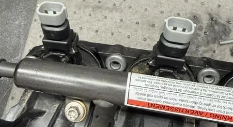
Reinstall the fuel rail onto the intake manifold. Apply dielectric grease on the O-rings. Install the supplied injector adaptors. Make sure the adaptors fully seated.
- Step 48
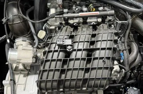
Reinstall the intake manifold onto the vehicle. Slide the manifold onto the (2) rubber grommets first then down to the intake ports. Be careful not to cut the gasket. Install the intake manifold hardware and torque to 80 in-lb (9 NM). Reconnect the injectors, MAP sensor, throttle body, and fuel rail. Zip tie the harness back in the OEM location.
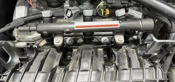
- Step 49
Remove the driver side rear wheel well by removing (7) push darts.
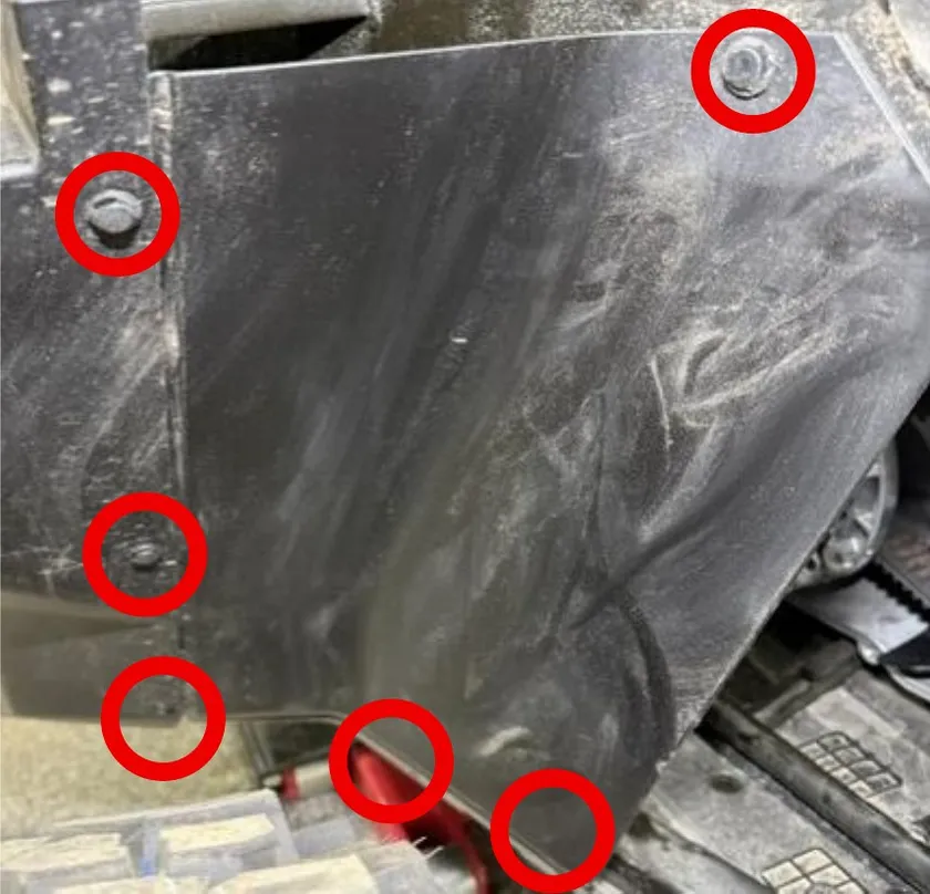
- Step 50
Remove (2) 10mm screws holding the gas tank in place.
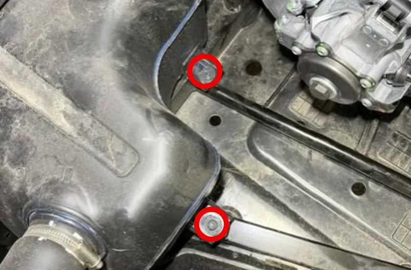
- Step 51
Locate the intercooler and brackets. (1) top bracket and (2) lower brackets.
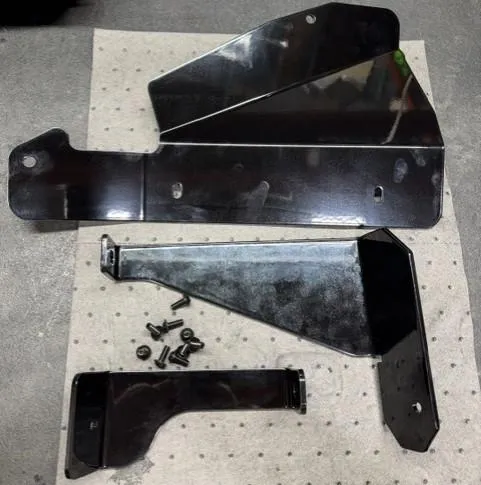
- Step 52
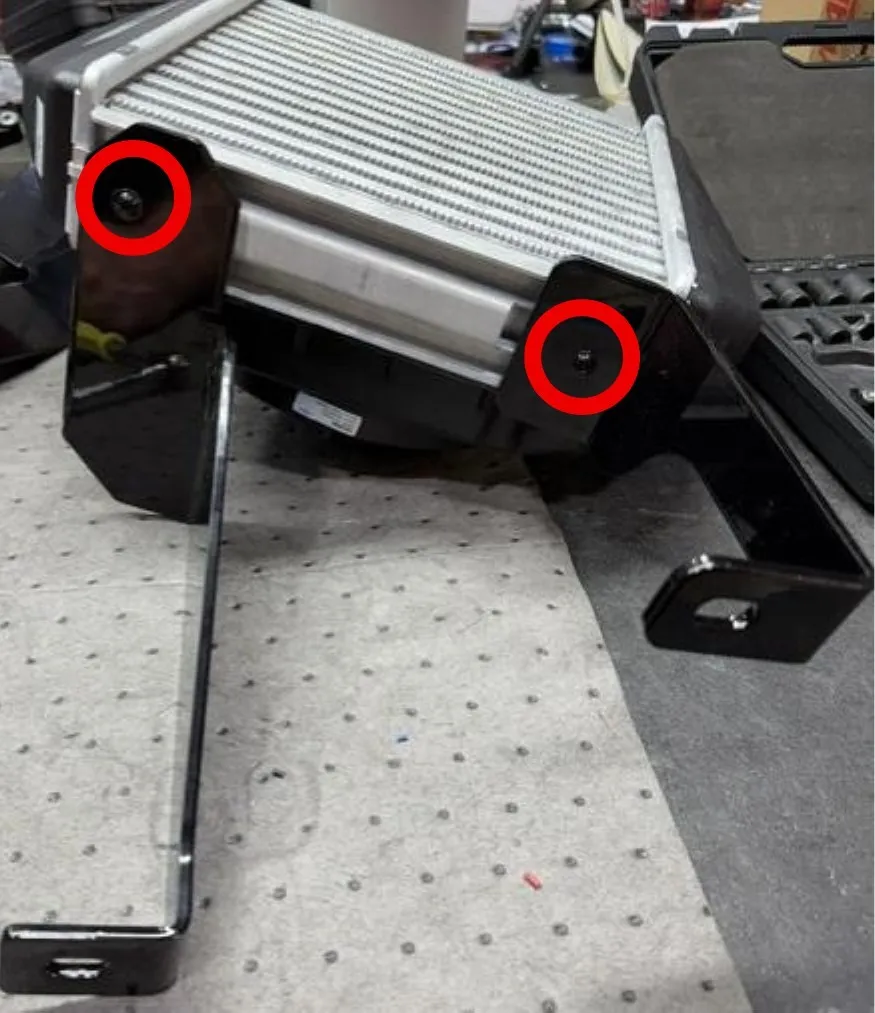
Install the (2) lower intercooler brackets as shown below. Leave them hand tight for now. Use supplied M6 hardware. The intercooler is symmetrical so there is no exact orientation.
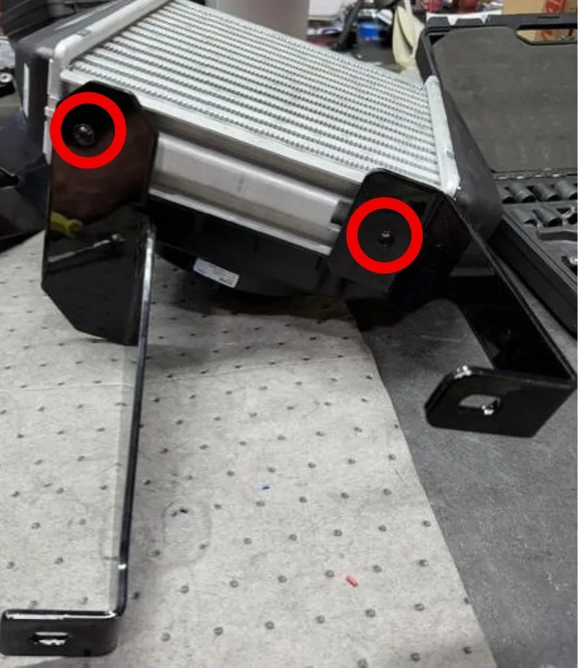
- Step 53
Install the intercooler into the vehicle where the airbox was originally. Install the mounts over the gas tank brackets. Reuse OEM hardware to fasten down. Make sure the intercooler fan is facing the engine. Tighten the intercooler brackets on the intercooler.
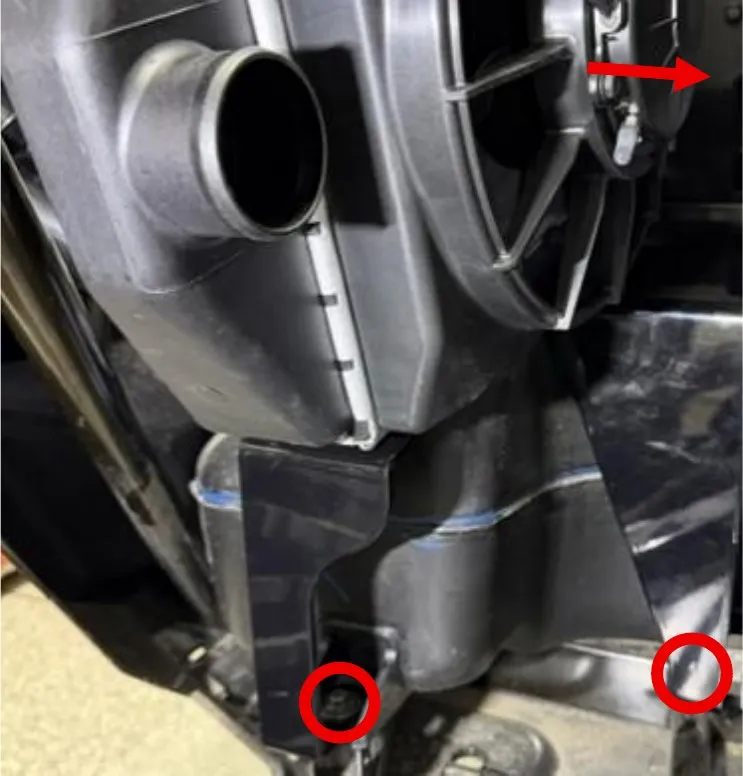
- Step 54
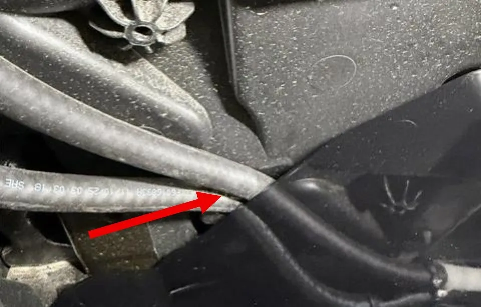
Install the upper intercooler mount using (2) M6 screws on the intercooler and (2) push darts on the frame rail. Route the (2) 1/4" vent lines towards the right to they don’t get pinched.
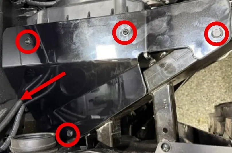
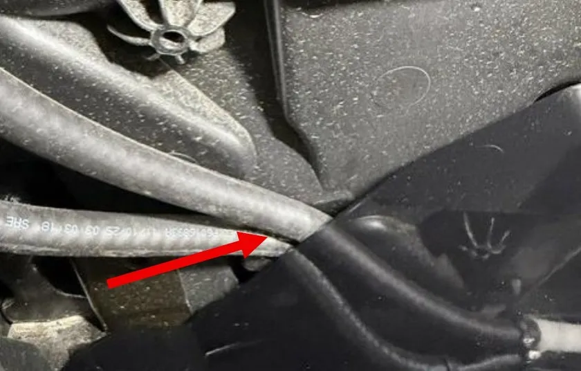
- Step 55
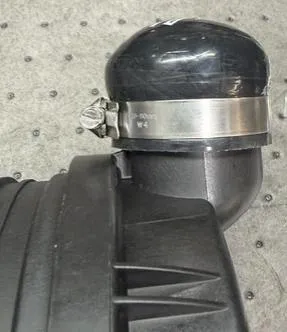
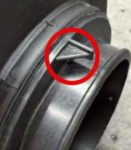
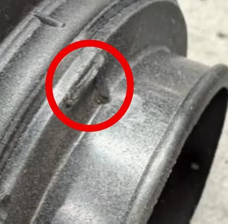
Locate the airbox and hardware. Check to make sure there is a filter in the airbox. Make sure the lid is latched and no debris on the inside of the filter. Install the 2.0” silicone cap and fasten down with a 40-60mm worm drive. On the inlet side, cut the plastic tab off flush, or sand off.
- Step 56
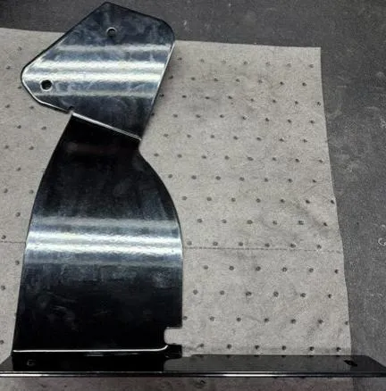
Locate the airbox bracket and hardware.
- Step 57
On the driver side of the vehicle, remove the (2) 10mm screws and washers holding the rear skid plate on.
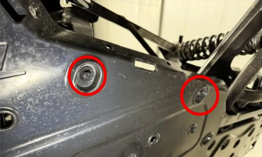
- Step 58
Install the airbox bracket underneath the lower frame rail and above the skid plate. Align the mounting holes with the skid plate and reinstall the OEM hardware.
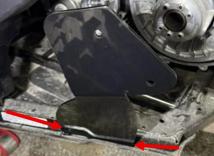
- Step 59
Install the airbox to the bracket using supplied M8 hardware.
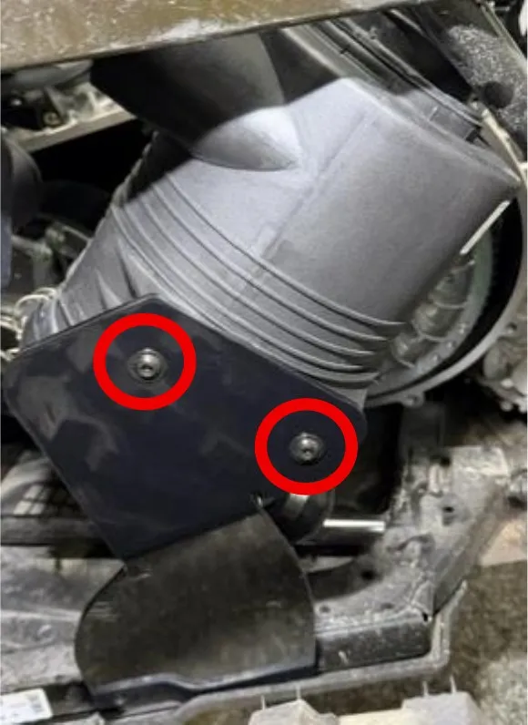
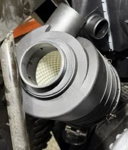
- Step 60
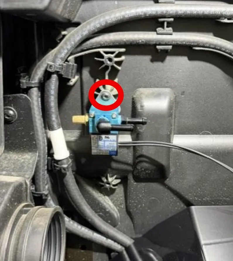
Locate the boost controller solenoid with bracket. Install the BCS with supplied Torx screw for plastic. Install into the firewall stud located by the intake tube.
- Step 61
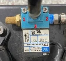
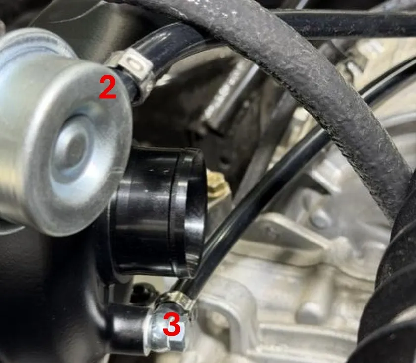
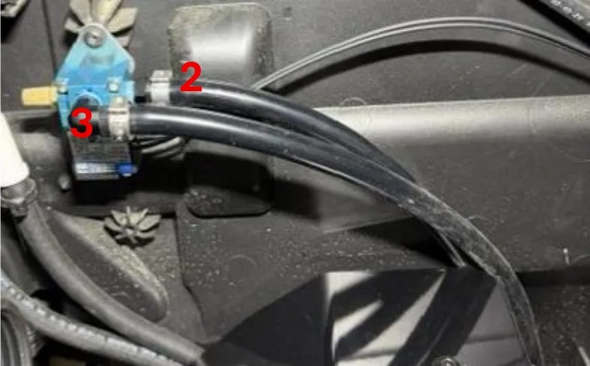
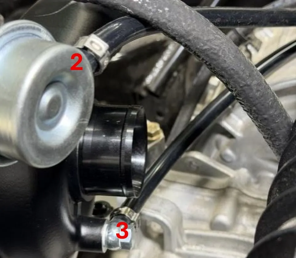
Connect the hoses to the turbocharger and wastegate as shown below. Port 1 is the muffler. Port 2 will connect to the wastegate. Port 3 will connect to the turbocharger.
- Step 62
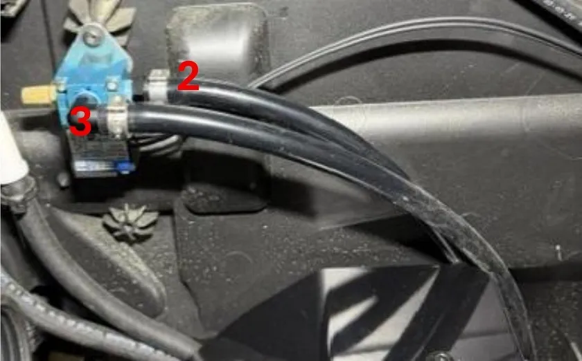
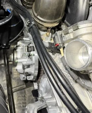
Route the hoses above the CVT housing and zip tie loosely to the plastic hose support. Use supplied (4) 13.3mm pinch clamps to fasten the hoses down.
- Step 63
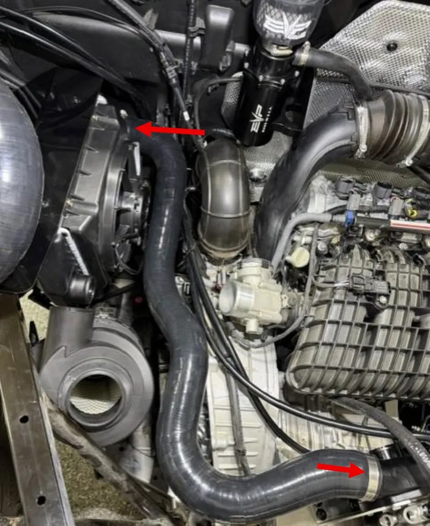
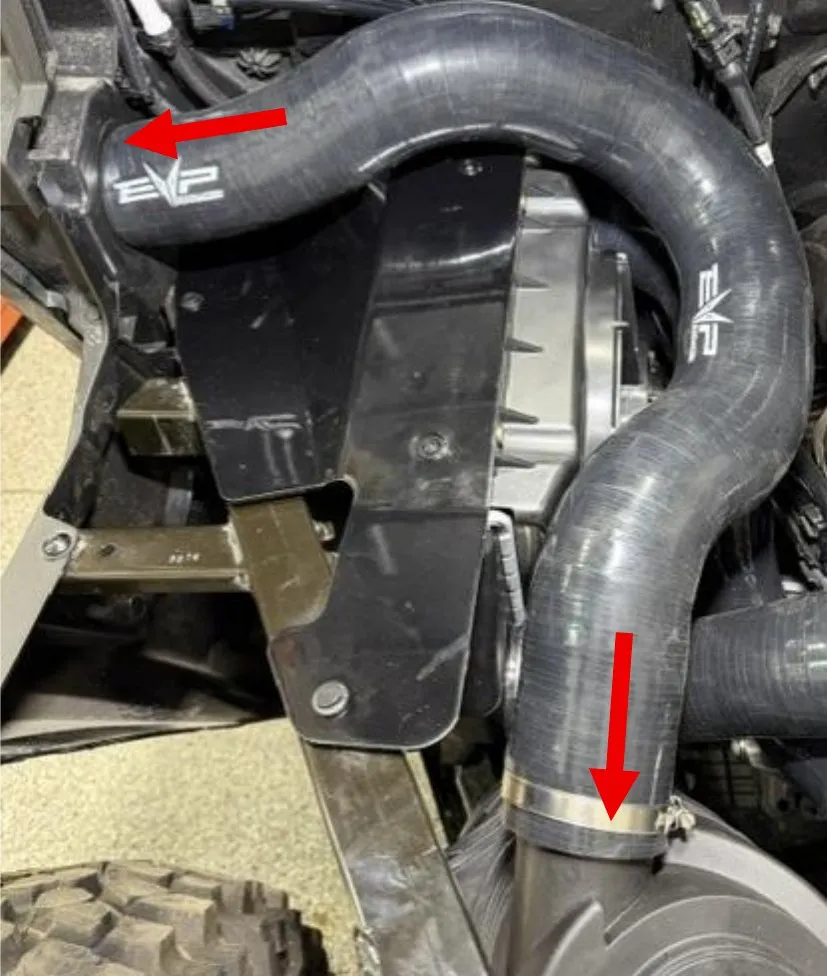
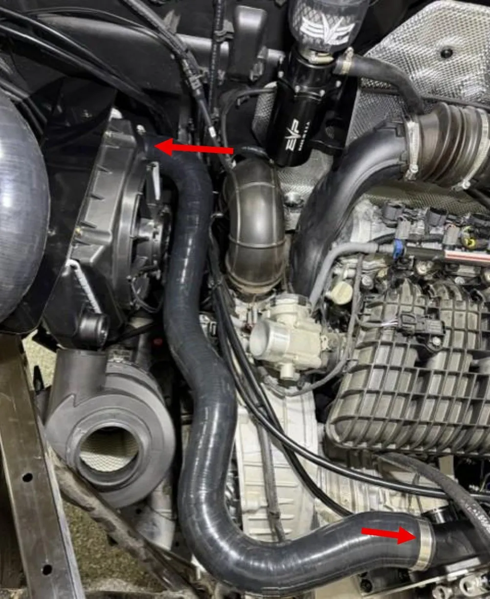
Install the charge tube between the intercooler and turbocharger compressor outlet. Use (2) 40-60mm worm drive clamps.
- Step 64
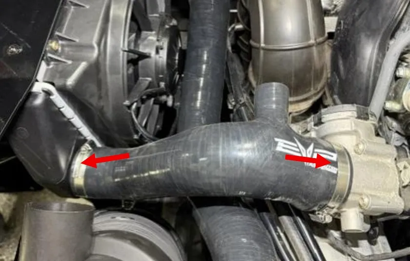
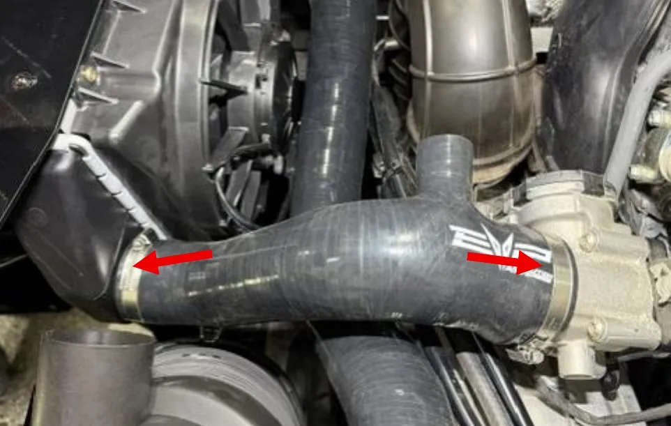
Install the intercooler to throttle body charge tube. Use (2) 50-70mm worm drive clamps. This tube comes with a 1.0” port for a BOV or BRV. If you are not running a valve, install the 1.0” plug with worm drive clamp.
- Step 65
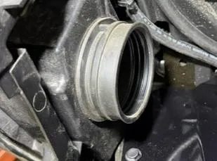
Install the fresh air inlet to airbox tube. Remove the OEM rubber out of the side panel. Use (1) 60-80mm worm drive. The other end has a rib to staying in the side panel.

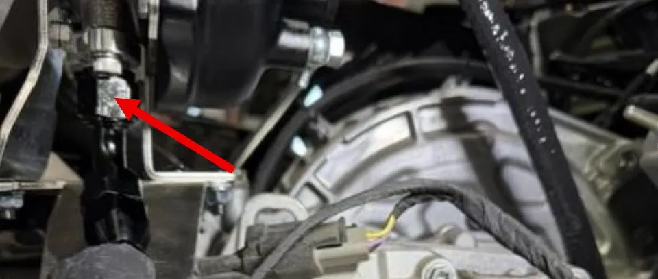
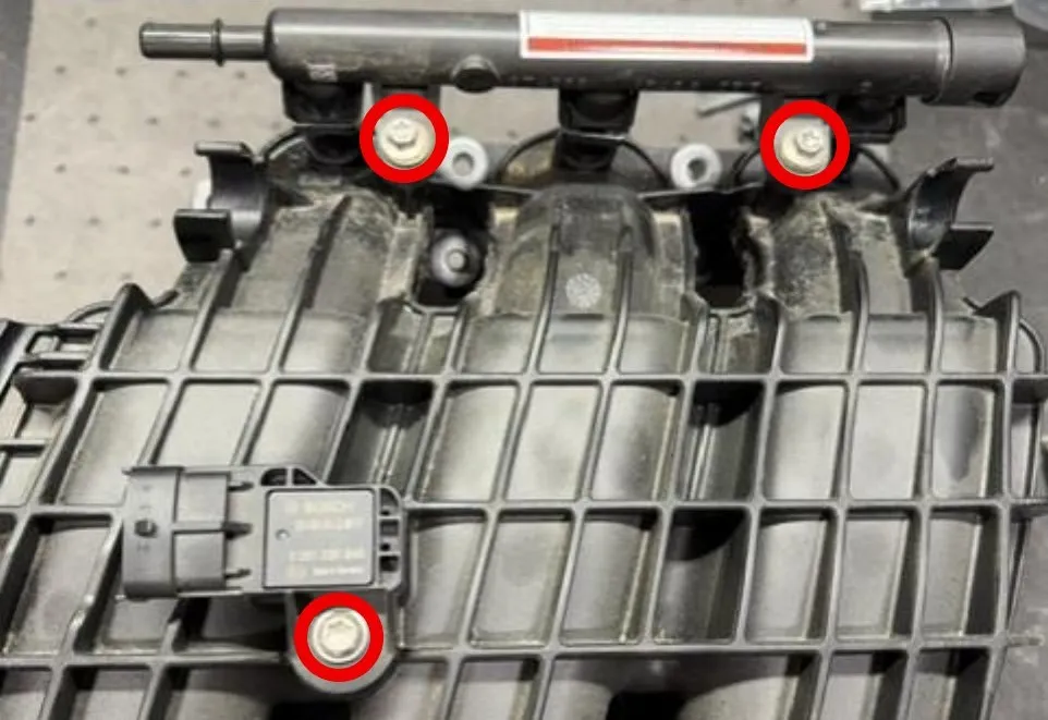
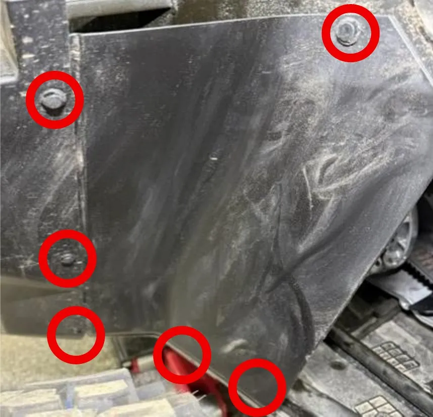
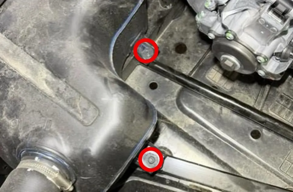
SNORKEL ONLY: if running a snorkel kit, remove (3) T-30 screws holding the driver side snorkel onto the vehicle. Remove snorkel.
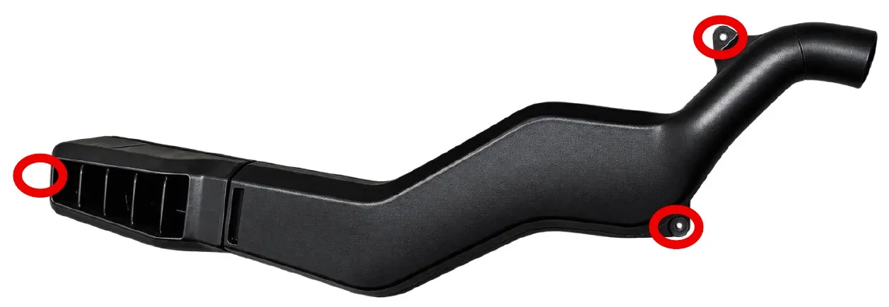
On the exit side of the intake snorkel, measure out 2.25” on the inside bend and 3.50” on the outside bend. Cut the snorkel exit off as shown in the photos below.
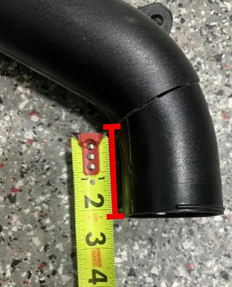
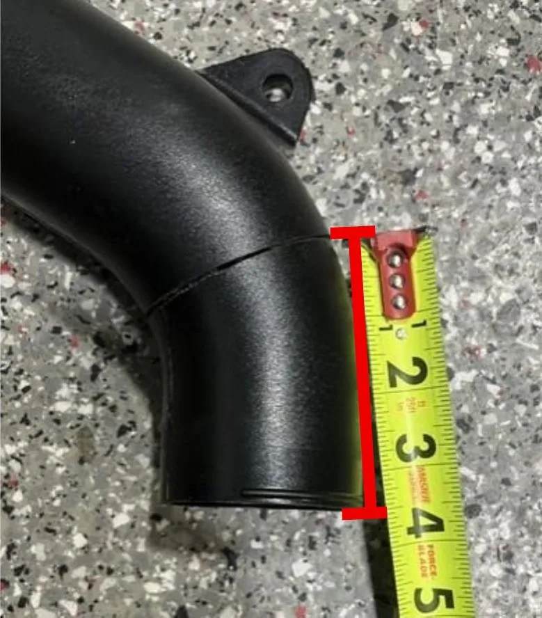
Reinstall the snorkel tube to the vehicle. Install supplied silicone between the snorkel and airbox. Fasten down with worm drive clamps.
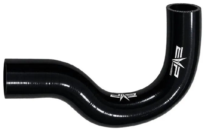
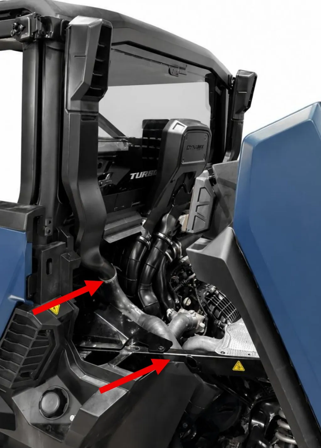
- Step 66
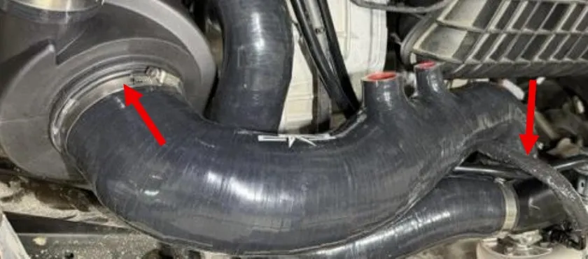
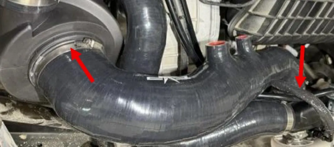
Install the airbox to turbocharger inlet tube. Fasten down with (1) 40-60mm and (1) 70-90mm worm drive clamp. This tube comes with a 5/8” and 1.0” port. If you ARE running a catch can you can plug the 5/8” port. Otherwise connect the crank case vent to this port. The 1.0” port is for the BRV return hose; you can plug this port as well.
- Step 67
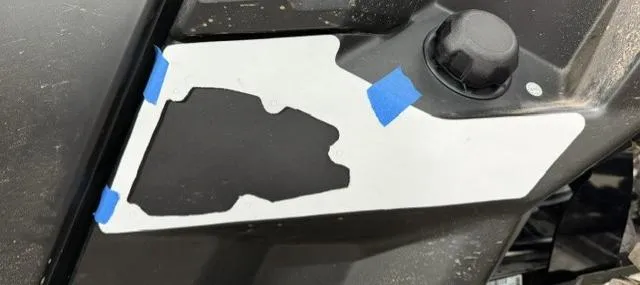
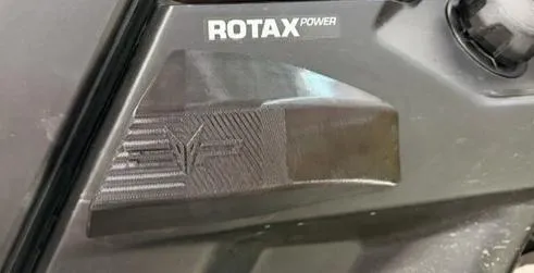
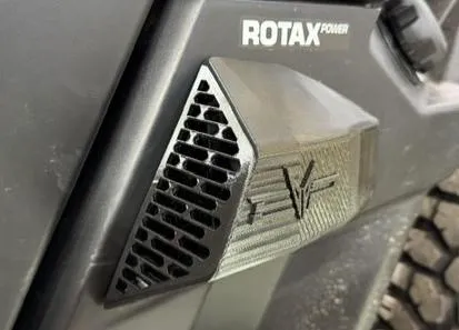
Install the air scoop template onto the driver side panel, located by the fuel fill neck. Once the template is square, tape it down.
- Step 68
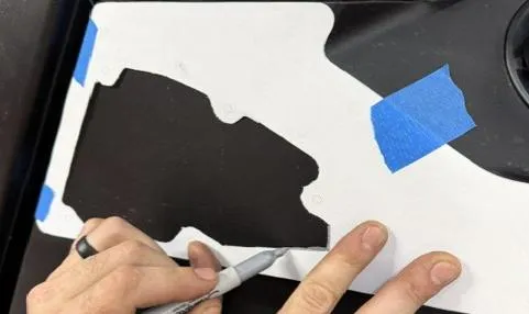
Outline the template with (5) 1/4" holes with a silver sharpie or you can cut with the template on the vehicle.
- Step 69
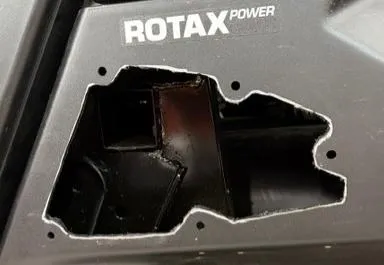
Cut the template out with a Dremel or air tool. Sand the rough edges away. With a rag and brake cleaner you can remove the silver sharpie line. Use a 1/4" or 9/32” drill bit.
- Step 70
Install the air scoop by fastening (5) M6 screws from the backside. You can remove the intercooler to make the job easier, it can be done with the intercooler mounted.
- Step 71
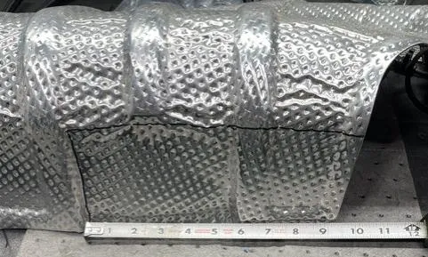
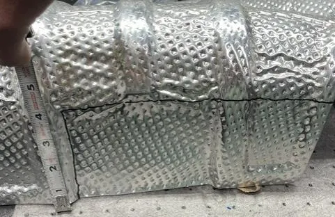
locate the OEM muffler heat shield. With a cutting tool, notch out a 9” x 4” square on the left side of the shield. This will make room for the OEM heat shield to go back on. Reinstall the heat shield with (6) push darts.
Need technical support?
Submit a ticket with your vehicle and what you're seeing, and our support team will get back to you.
