Defender HD-11 DT-200 Boost Controller With Wire Harness Assy

Defender HD-11 DT-200 Boost Controller With Wire Harness Assy

SKU
3002010021
Revision
REV_061826

In the box

Parts and tools

Included parts

  • 1Boost Controller Box with Harness
  • 1Accessory Power Harness
  • 1Boost Control Solenoid Harness
  • 1Intercooler & Oil Pump Relay Harness
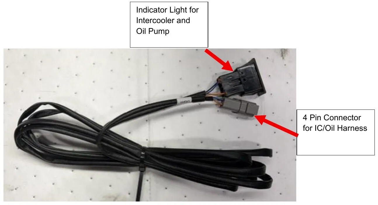
  • 1Indicator Light Harness
  • 1Intercooler Extension Harness

Required tools

  • Push dart removal tool
  • T-20, T-30 torx
  • 8, 10mm Socket
  • Side cutters
  • Ratchet
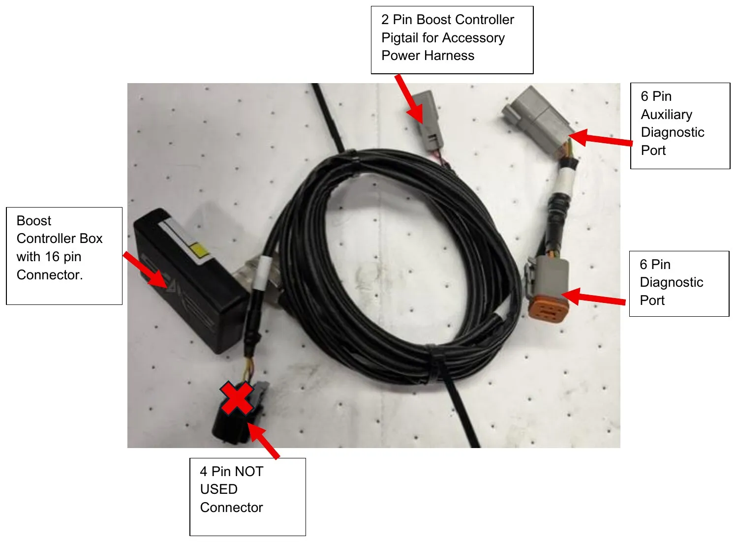
Boost Controller Box (BCB) Harness
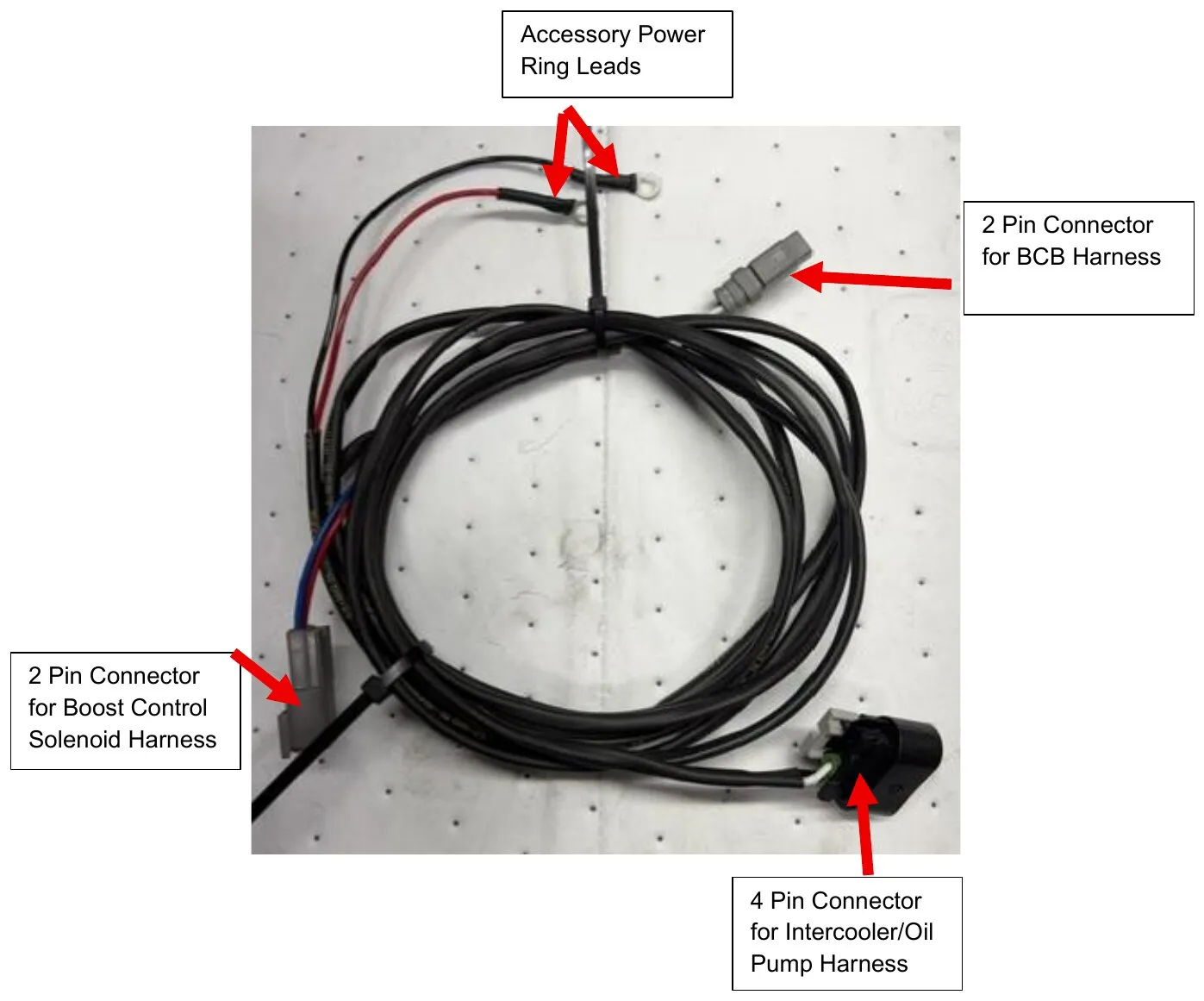
Accessory Power Harness
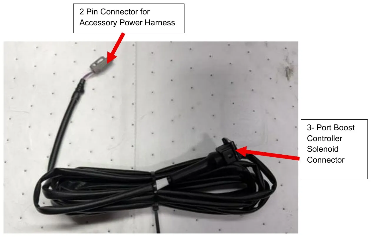
Boost Control Solenoid Harness
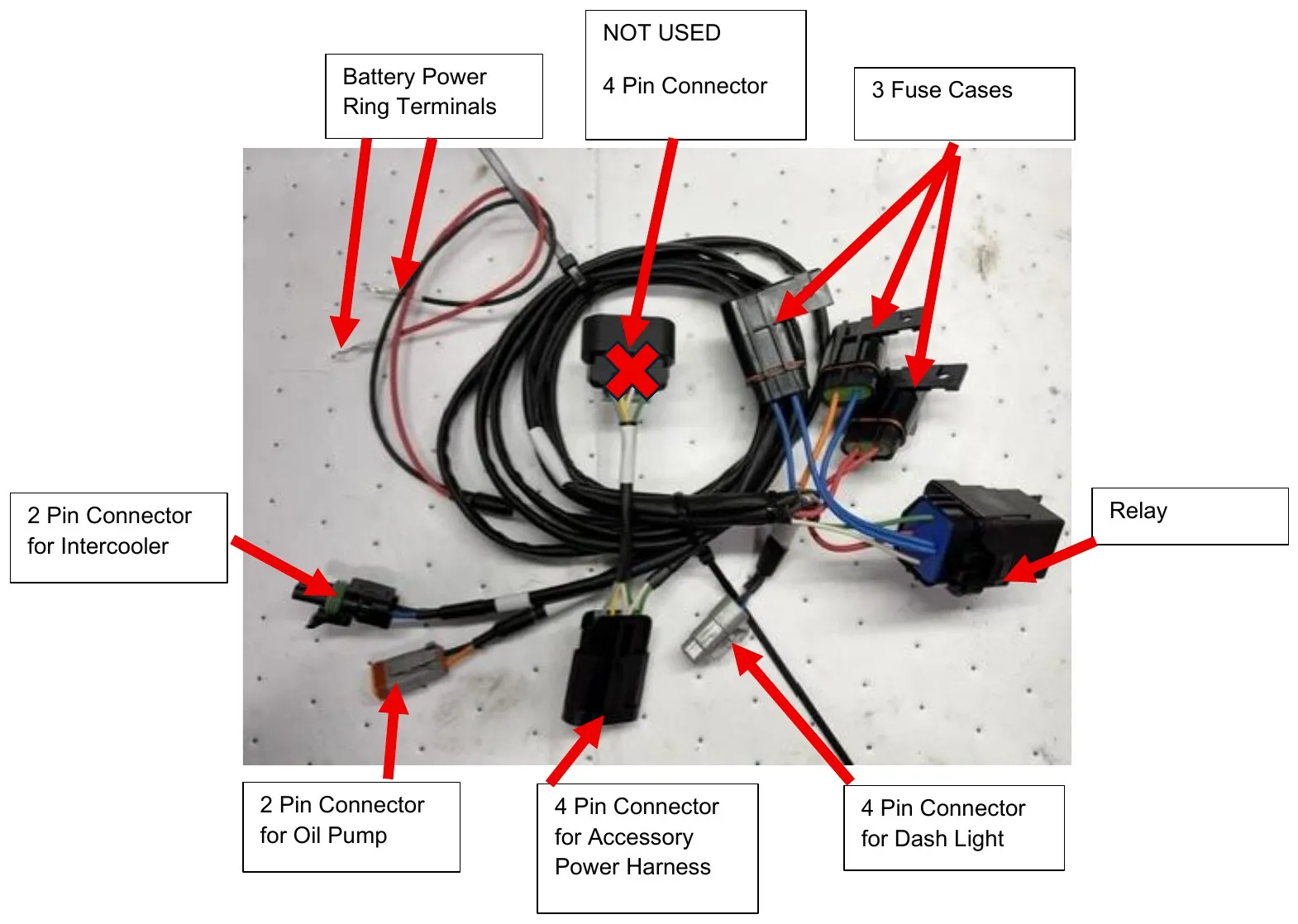
Intercooler & Oil Pump Relay Harness
Indicator Light Harness
Intercooler Extension Harness

Procedure

Installation

  1. Step 1

    Remove rubber matting from floor, It is held down by several trim clips that easily pull up with mat.

  2. Step 2

    Remove (8) push darts and remove front center floor panel.
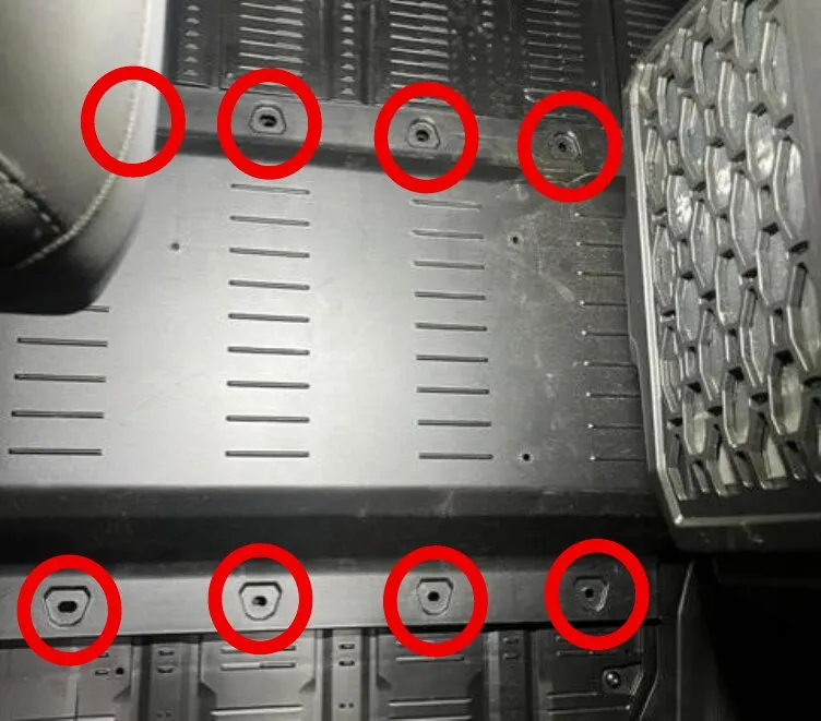
    Remove (8) push darts and remove front center floor panel.
    Remove (8) push darts and remove front center floor panel.
  3. Step 3

    Remove the (8) T-30 screws from the passenger side floor and remove panel.
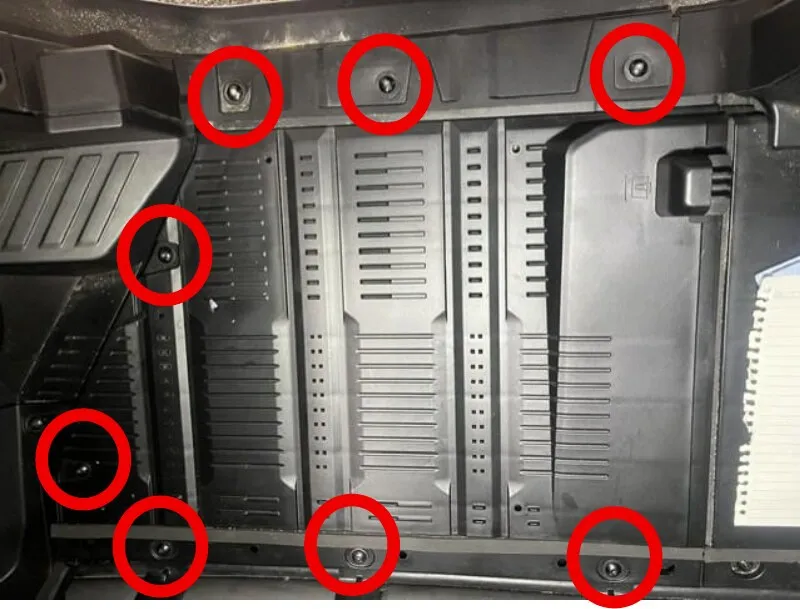
    Remove the (8) T-30 screws from the passenger side floor and remove panel.
  4. Step 4

    Remove the small panel on the front left of passenger side footwell. It is held in place by (2) T-30 and (2) T-20 screws.
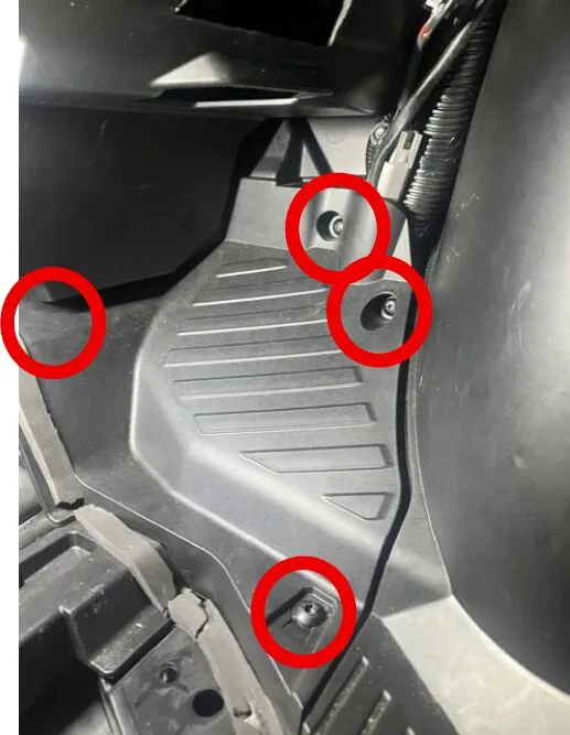
    Remove the small panel on the front left of passenger side footwell.
  5. Step 5

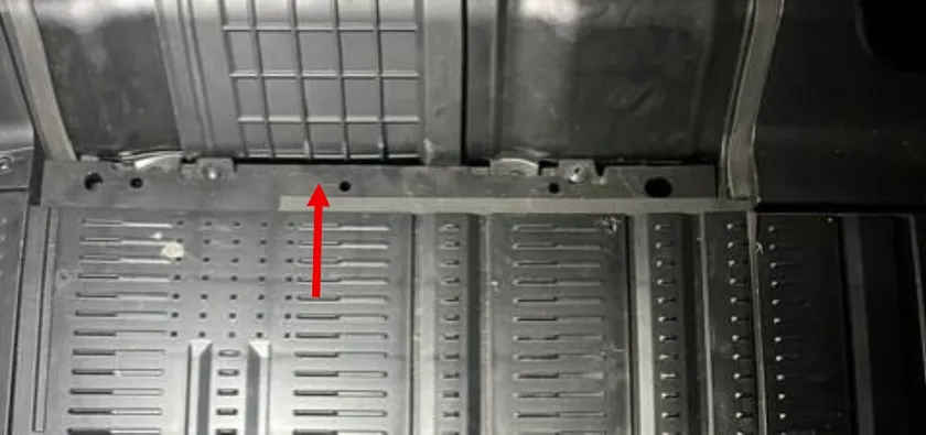
    4 Door Models Only: Remove (10) push darts from rear center panel. The front of the panel will have (1) 8mm screw threaded up from the bottom – remove. Remove the flexible rubber tube connecting to the rear air vents. Pull up and slide entire center panel forward.
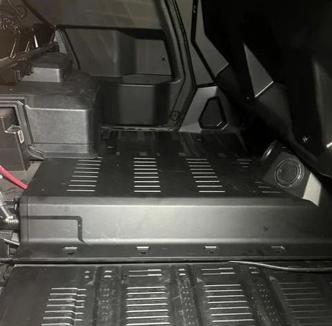
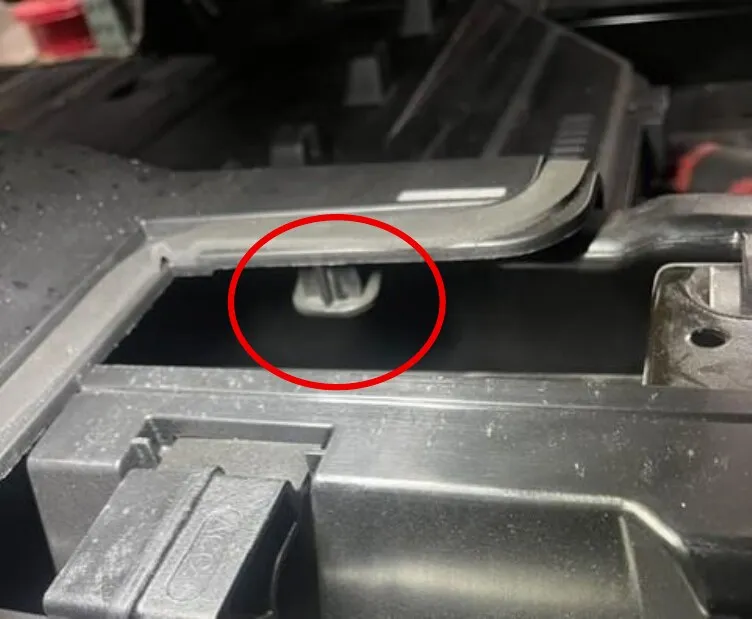
    4 Door Models Only: Remove (10) push darts from rear center panel.
    The front of the panel will have (1) 8mm screw threaded up from the bottom – remove.
    Pull up and slide entire center panel forward.
  6. Step 6

    On both sides remove (2) push darts and (1) T-30 from A-pillars. Use a pick to pull shock tab out.
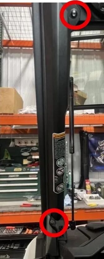
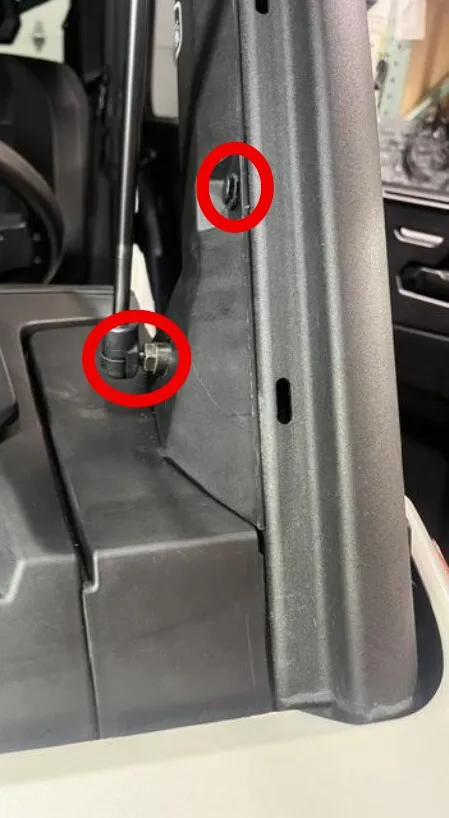
    On both sides remove (2) push darts and (1) T-30 from A-pillars.
    On both sides remove (2) push darts and (1) T-30 from A-pillars.
  7. Step 7

    Remove A-pillar plastic, push up and slide forward. Under the panels remove (2) T-30 screws on both sides.
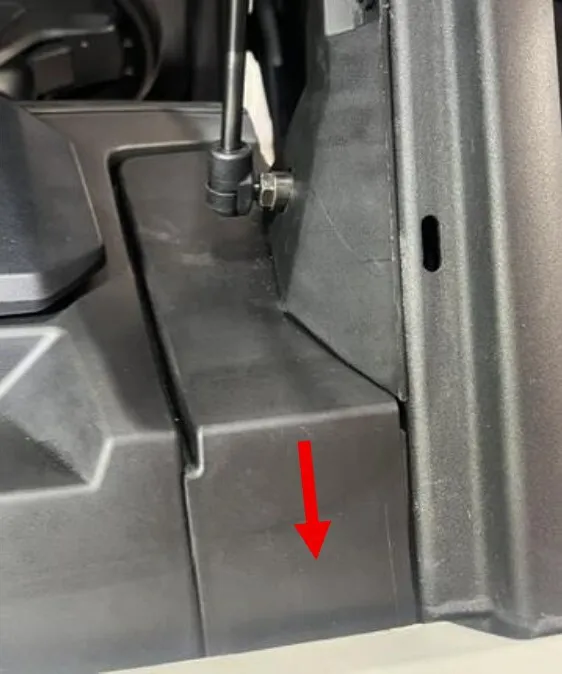
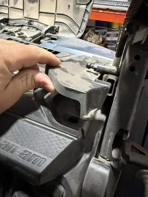
    Remove A-pillar plastic, push up and slide forward.
    Remove A-pillar plastic, push up and slide forward.
    Under the panels remove (2) T-30 screws on both sides.
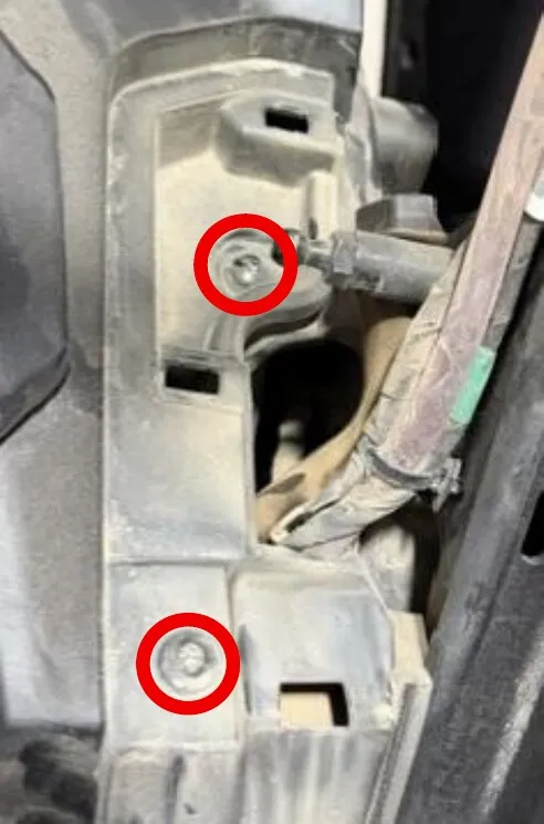
  8. Step 8

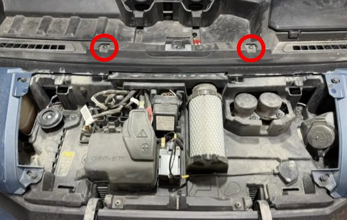
    Lift the front hood forward. Remove (2) T-30 screws from center of dash.
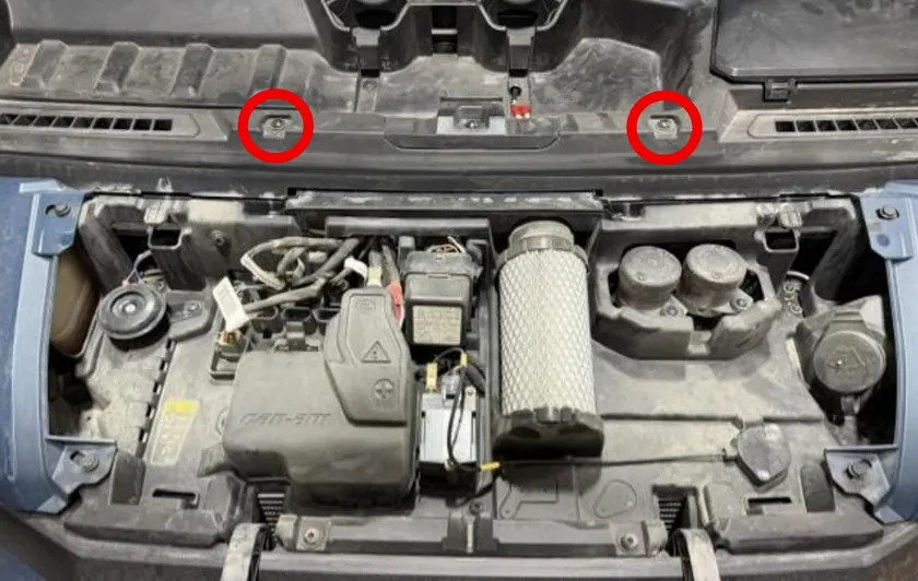
    Remove (2) T-30 screws from center of dash.
  9. Step 9

    Lift the dash up on the passenger side, zip tie to the shock.
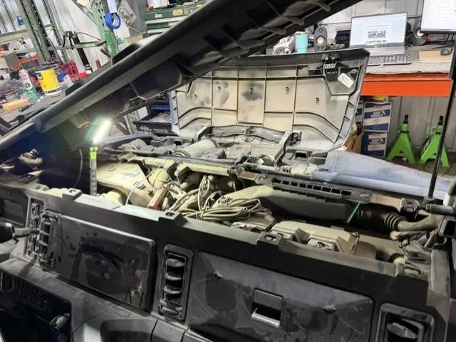
    Lift the dash up on the passenger side, zip tie to the shock.
  10. Step 10

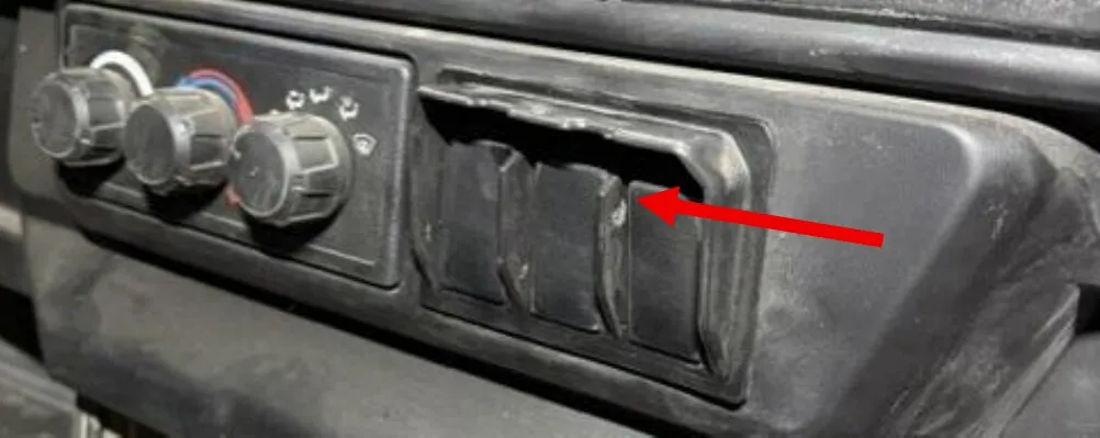
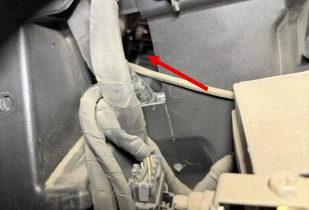
    Remove the 3 button blank out of the dash. Route the boost control box harness from under the passenger foot well over to where the blank switches were. Continue running the diagnostic connectors up behind the dash to the hood area.
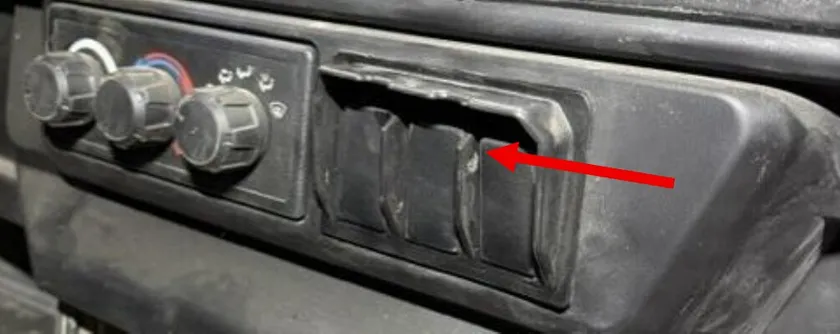
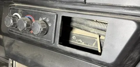
    Remove the 3 button blank out of the dash.
    Remove the 3 button blank out of the dash.
    Route the boost control box harness from under the passenger foot well over to where the blank switches were.
    Continue running the diagnostic connectors up behind the dash to the hood area.
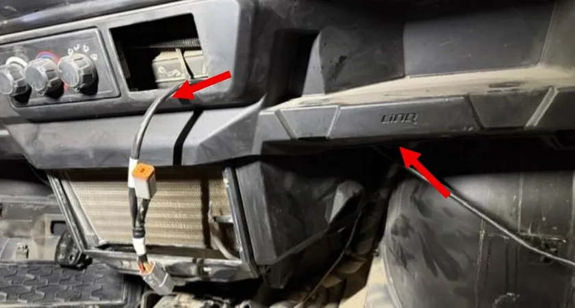
  11. Step 11

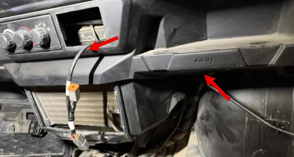
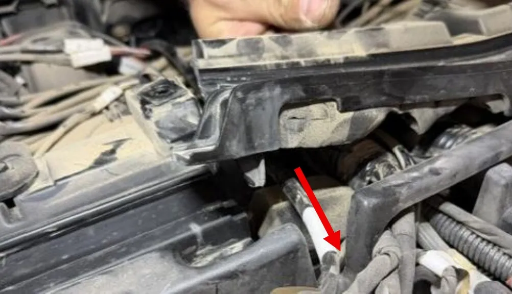
    Remove (1) T-30 screw holding the plastic dash down. Route the harness underneath this to the diagnostic port. Connect one connector to the diagnostic port and the other connector into the holding device.
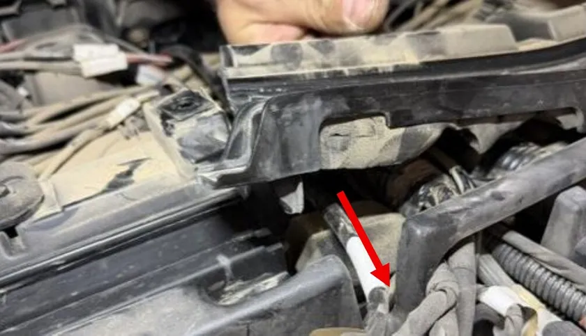
    Route the harness underneath this to the diagnostic port.
    Connect one connector to the diagnostic port and the other connector into the holding device.
  12. Step 12

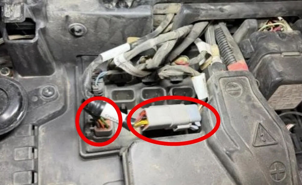
    On the back side of that harness you will find the 90 Degree 16 pin connector and 2 pin.
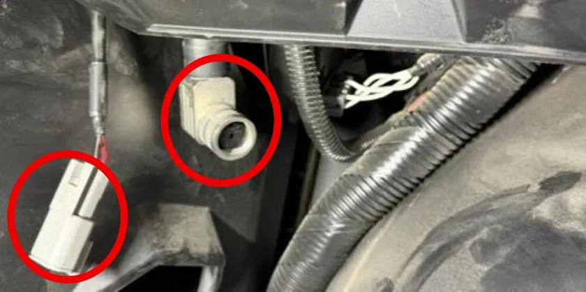
    On the back side of that harness you will find the 90 Degree 16 pin connector and 2 pin.
  13. Step 13

    This pigtail and connector will not be used. It will be zip tied with the rest later.
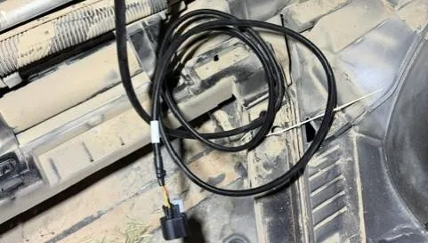
    This pigtail and connector will not be used.
  14. Step 14

    Install half the Velcro to the backside of the black box.
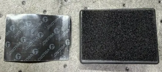
    Install half the Velcro to the backside of the black box.
  15. Step 15

    Connect the black box to the 16 pin connector. DO NOT OVER TIGHTEN.
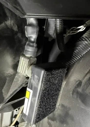
    Connect the black box to the 16 pin connector.
  16. Step 16

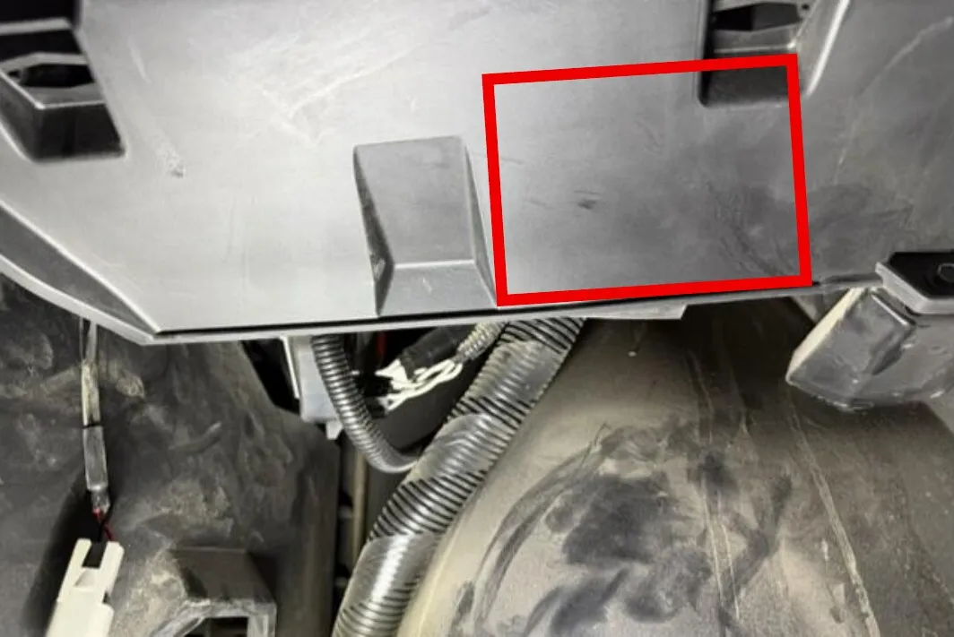
    Test fit the black box under the dash, clean an area off with cleaner. Install the other side of Velcro on the back side of this plastic. Install the black box on the Velcro. Red square is for the placement on the backside. This will keep it out of eyesight.
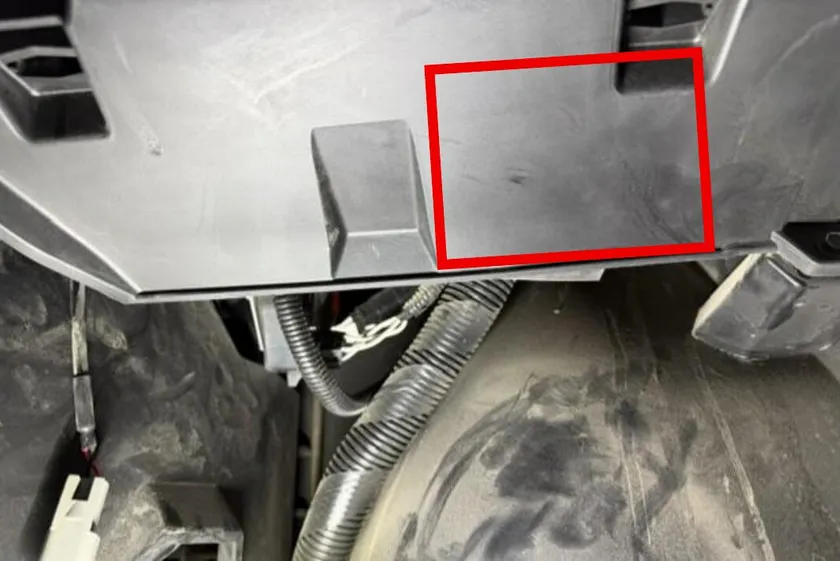
    Red square is for the placement on the backside.
  17. Step 17

    Route the terminal leads from the accessory harness up the same way.
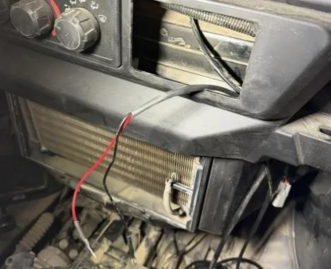
    Route the terminal leads from the accessory harness up the same way.
  18. Step 18

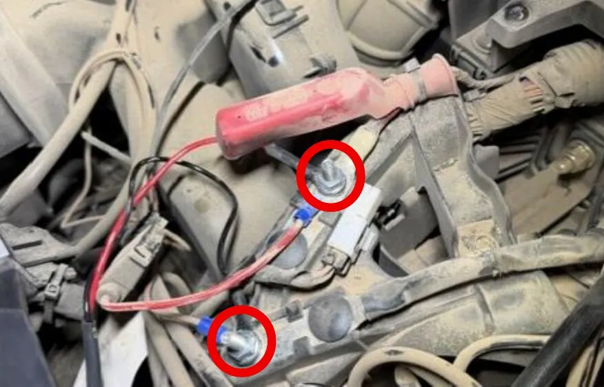
    Underneath the dash you will find accessory power terminals. Connect the red wire to positive and black to negative.
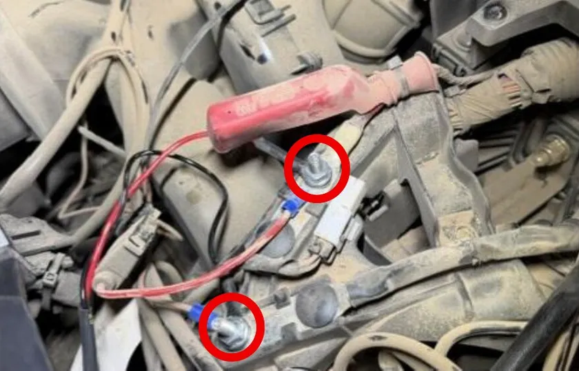
    Connect the red wire to positive and black to negative.
  19. Step 19

    Connect one side of the 2 pin accessory power harness to the first harness (BCB) connector. Connect the other 2 pin accessory power connector to the boost control solenoid harness. This harness will connect to the 3-Port boost controller.
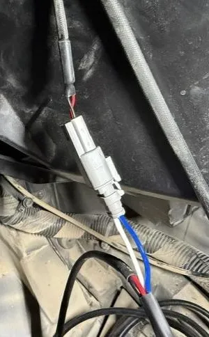
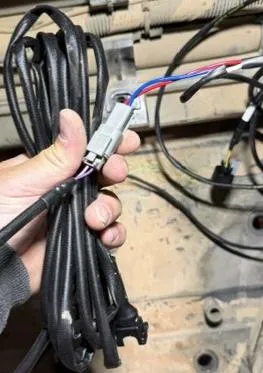
    Connect one side of the 2 pin accessory power harness to the first harness (BCB) connector.
    Connect the other 2 pin accessory power connector to the boost control solenoid harness.
  20. Step 20

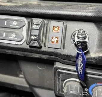
    Remove a blank switch somewhere on the dash, you can put it up high or down low. We install ours next to the key. Remove the blank. Route the indicator light harness the same as the others. Install the indicator light into the socket, push into the dash.
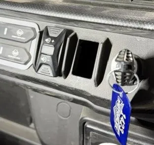
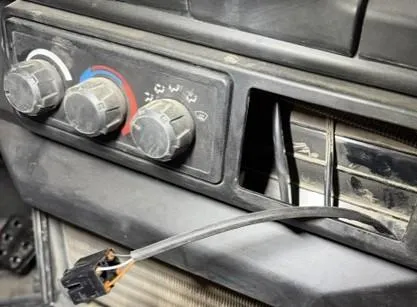
    Remove a blank switch somewhere on the dash, you can put it up high or down low.
    Route the indicator light harness the same as the others.
    Install the indicator light into the socket, push into the dash.
  21. Step 21

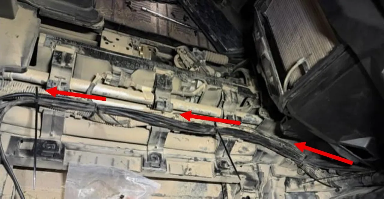
    Using supplied zip-ties, secure harness to factory harness from the front passenger wheel well back to battery location.
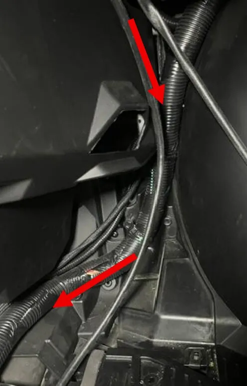
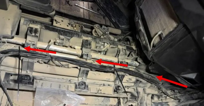
    Using supplied zip-ties, secure harness to factory harness from the front passenger wheel well back to battery location.
    Using supplied zip-ties, secure harness to factory harness from the front passenger wheel well back to battery location.
  22. Step 22

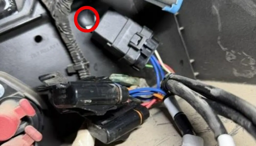
    Located by the battery are (2) holes labeled relay. With the supplied push dart, install the relay from the intercooler/oil pump harness.
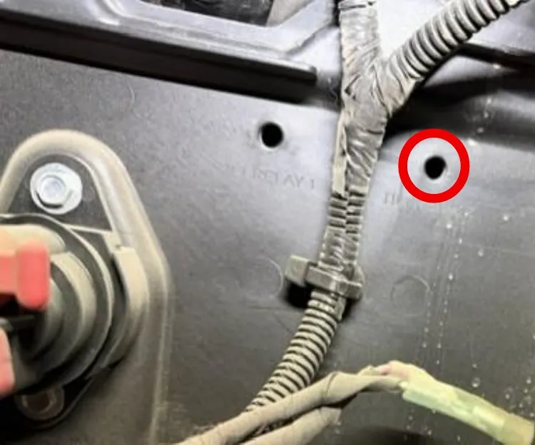
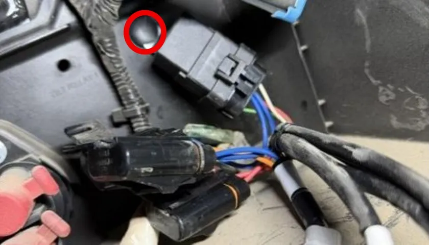
    Located by the battery are (2) holes labeled relay.
    With the supplied push dart, install the relay from the intercooler/oil pump harness.
  23. Step 23

    Install the 4-pin connector labeled fuel from the accessory harness to the mating 4-pin connector on the intercooler/oil pump relay harness. There will be a 4-pin connector that will NOT be used.
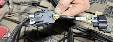
    Install the 4-pin connector labeled fuel from the accessory harness to the mating 4-pin connector on the intercooler/oil pump relay harness.
  24. Step 24

    Connect the 4-pin indicator light harness to the relay harness. Both labeled light.
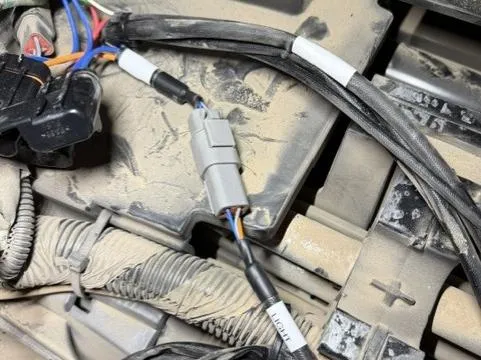
    Connect the 4-pin indicator light harness to the relay harness.
  25. Step 25

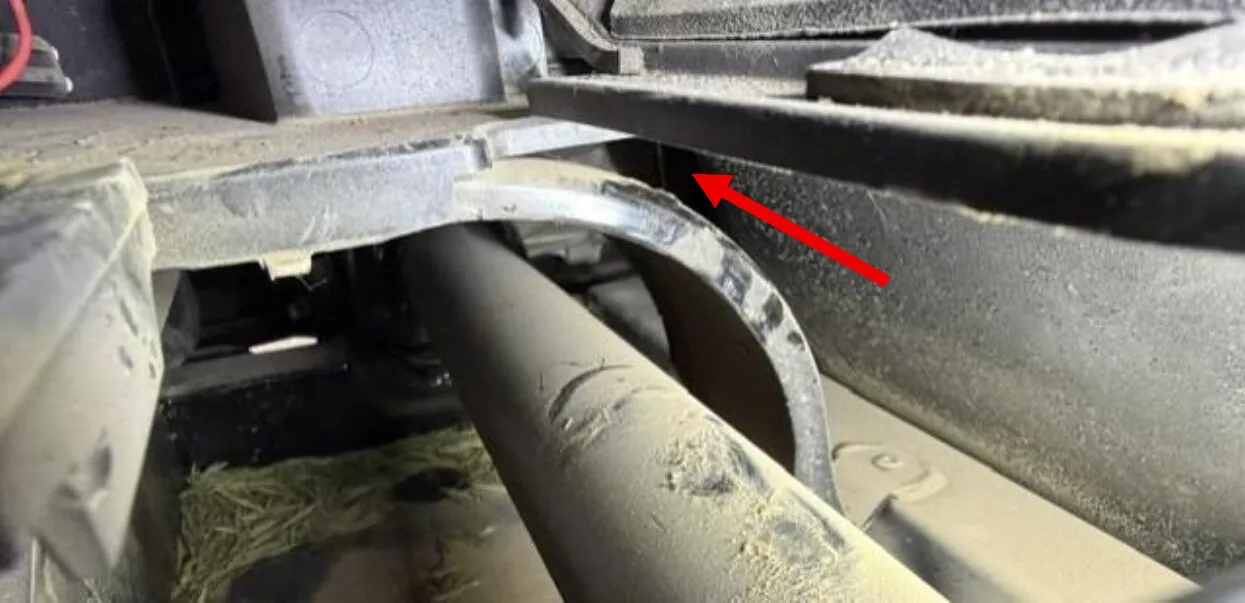
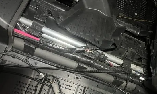
    Route the intercooler harness on top of the metal driveshaft bracket, through the firewall and over to the intercooler location. There is an extension harness if needed. Depending on your routing, you may not need it.
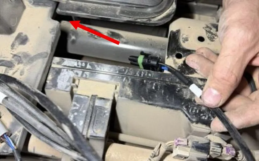
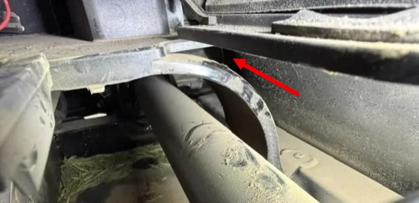
    Route the intercooler harness on top of the metal driveshaft bracket, through the firewall and over to the intercooler location.
    Route the intercooler harness on top of the metal driveshaft bracket, through the firewall and over to the intercooler location.
  26. Step 26

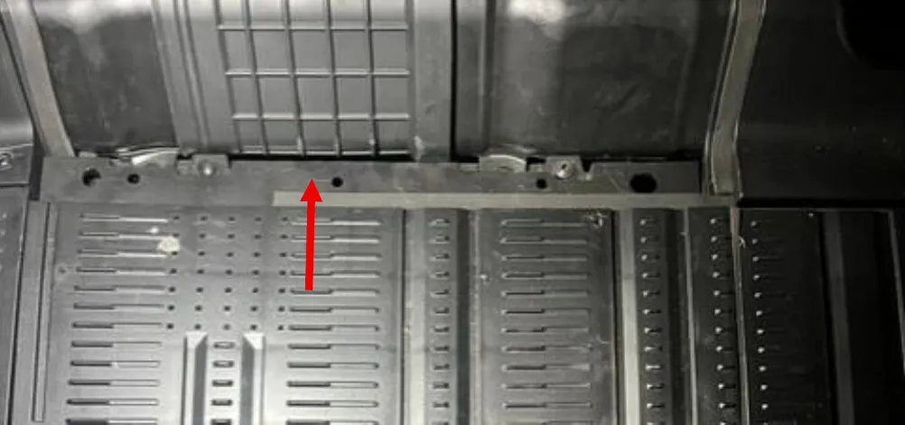
    Locate the oil pump and boost solenoid harnesses, route them behind the battery, through the firewall out into the engine bay.
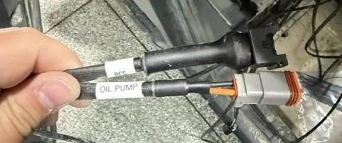
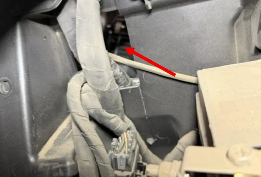
    Locate the oil pump and boost solenoid harnesses, route them behind the battery, through the firewall out into the engine bay.
    Locate the oil pump and boost solenoid harnesses, route them behind the battery, through the firewall out into the engine bay.
  27. Step 27

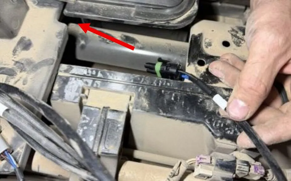
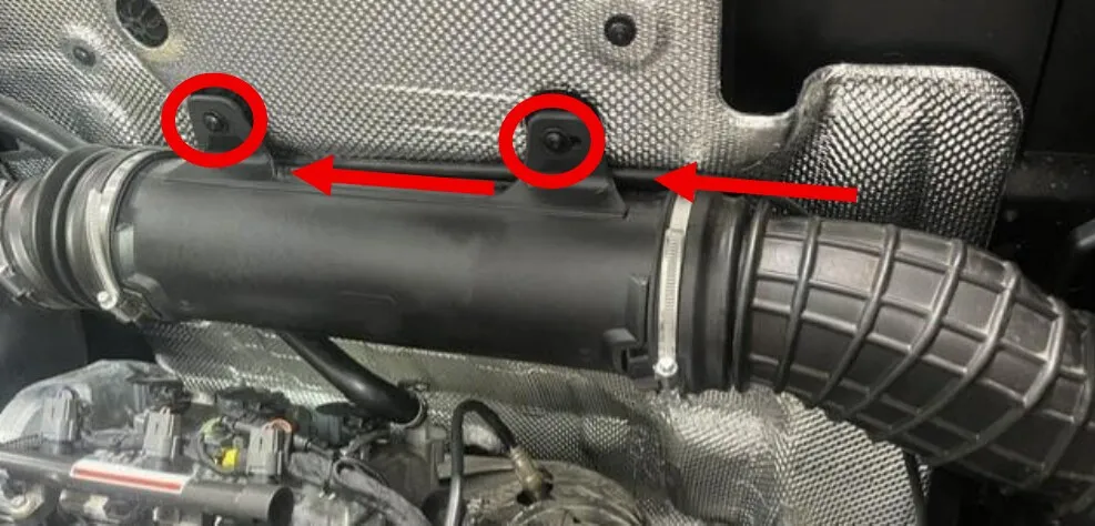
    The oil pump harness will connect to the oil pump on right side frame rail. The boost controller harness will route across CVT fresh air duct to drivers side of vehicle. Remove (2) T-20 screws off the air duct and run the harness behind.
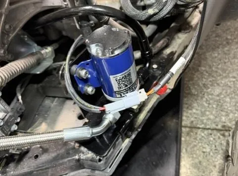
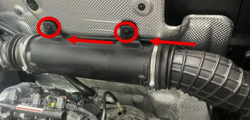
    The oil pump harness will connect to the oil pump on right side frame rail.
    Remove (2) T-20 screws off the air duct and run the harness behind.
  28. Step 28

    Install the relay harness ring terminals to the battery.

    Install the relay harness ring terminals to the battery.
When you’re done

After installation

Note

Before reinstalling all the interior, and the turbo kit is installed, turn the vehicle on and make sure both indicator lights are ON. If the lights are OFF that means there is now power to the intercooler or oil pump. If everything works as it should, zip tie all the harness wires tight and reinstall the interior.

Emissions notice. This product is exempt from the emission standards and related requirements of 40 C.F.R. § 1051 as provided by 40 C.F.R. § 1051.620, and California law [e.g., vehicle code §§ 27156 and 38391]. This product is sold only for use in connection with EPA certified, purpose-built, nonroad vehicles used solely for closed course, nonroad competition/racing and not used for any recreational purpose or on public highways or right of ways maintained by and open to the public. This product is sold only in connection with machines that do not fall under state and/or federal noise or emission standards/regulations. Purchasers who/that purchase this product represent and warrant that the product is purchased only in connection with EPA-certified, emission-regulations-exempt and noise-regulations-exempt competition/racing vehicles as interpreted under applicable state and/or federal law.

Need technical support?

Submit a ticket with your vehicle and what you're seeing, and our support team will get back to you.

Contact Support
We use cookies to improve your experience on our website. Read about how we use cookies in our Privacy Policy. By browsing this website, you agree to our use of cookies. privacy policy
accept

Your cart

×
×