 BUY NOW, PAY LATER. Starting at 0% APR


This is a high-performance upgrade! Although we have gone through great lengths to build safety into the upgrade turbo system, the fact is installing any upgrade / turbo system requires care in both operation and installation. Poor fuel, improper setup or any number of things that are done incorrectly can damage your engine!
Can-Am 2020+ Defender Turbocharger 195 Upgrade System
2020+ Defender Turbocharger 195 Upgrade System
Before you start
Note
Expect 24–48-hour delay from the time you request a tune to when the file is enabled. Please create your CodeShooter account before starting the project.
Note
We recommend an oil change before initial start up
- You have likely voided the sound and exhaust emission standards of your country if applicable.
- This upgrade is intended for OFFROAD and RACING use only.
- This is a performance upgrade which will VOID your engine warranty especially if installed incorrectly or operated without regard to your instruments.
- The fuel requirements must be adhered to. Poor fuel can destroy an engine in seconds.
- Evolution Powersports bears no responsibility for damage caused to your vehicle by the installation of EVP products. The warranty on big turbo kits is 30 days from the date of purchase. Evolution Powersports, at its discretion will determine whether a part meets the warranty requirements. In no case is there any warranty from EVP for your vehicle or vehicles drivetrain. Although we have been careful to supply you with the highest quality parts possible, we assume no liability for damage to the vehicle or personal injury from installing or using any of our products.
- The installation of this kit is technical and mechanical in nature with many opportunities to make mistakes – mistakes that can be very costly. If you are not qualified to install this kit, bring your vehicle to one of our qualified installation centers to do the installation.
- This kit will make your vehicle faster, climb higher and accelerate more quickly and take a longer distance to brake than a stock tuned vehicle. If you are not capable of controlling the vehicle with the added performance, do not install the kit.
- High boost is hard on spark plugs – they must be changed frequently. If you experience misfire issues – Gap and replace the spark plugs.
- Do not ever allow a child or an unqualified driver to operate this vehicle.
| Level | Tunes | Max Boost (psi) | Spark Plug Gap | Spring | Waste Gate (psi) | Engine HP |
|---|---|---|---|---|---|---|
| DT-195-91 | 91 | 7 | .016 - .018 | EVP | 7 | 130 (91) |
| DT-195-110 | 110 | 13 | .016 - .018 | EVP | 7 | 160 (110) |
| DT-195-E85 | E85 | 16 | .016 - .018 | EVP | 7 | 195 (E85) |
| Tune Level | Fuel | Launch Control (RPM) | Elevation |
|---|---|---|---|
| DT-195-91 | 91 | N/A | All Elevations |
| DT-195-91-2500 | 91 | 2500 RPM | All Elevations |
| DT-195-110 | 110 | N/A | 0-5,000 ft |
| DT-195-110-2500 | 110 | 2500 RPM | 0-5,000 ft |
| DT-195-110 | 110 | N/A | 5,000-10,000 ft |
| DT-195-110-2500 | 110 | 2500 RPM | 5,000-10,000 ft |
| DT-195-E85 | E85 | N/A | 0-5,000 ft |
| DT-195-E85-2500 | E85 | 2500 RPM | 0-5,000 ft |
| DT-195-E85 | E85 | N/A | 5,000-10,000 ft |
| DT-195-E85-2500 | E85 | 2500 RPM | 5,000-10,000 ft |
Caution
It is crucial to change the tune in your vehicle to the corresponding elevation you are riding at.
Recommended Parts (Sold Separately)
- Defender BOV Kit (100FC0165)
- Defender Catch Can Kit
- Defender BRV Kit
- Clutch Kit or TAPP Clutch (Operating RPM 7300-7500 for 91octane)
Note
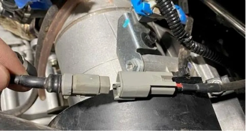
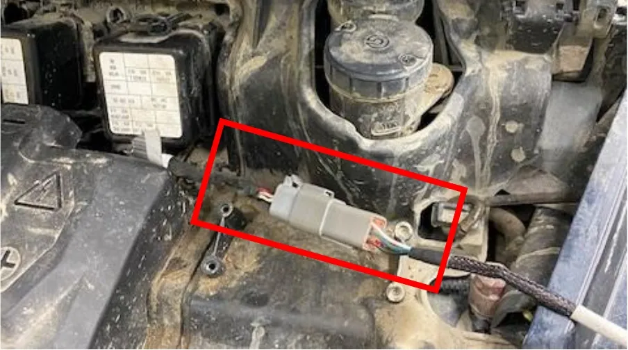
Locate the grey 6 pin diagnostic port under the hood of the vehicle. Connect the CodeShooter diagnostic cable. (2020-2022 uses BRP-2. 2022.5- Current uses BRP-1 cable).
Note
If the light on the CodeShooter does not turn on, you have the wrong cable. Connect the CodeShooter and follow the step-by-step instructions to flash the vehicle.
In the box
Parts and tools
Parts Included in Defender Turbo 195 Upgrade System
| 604FC0062 | 2020+ Defender Turbocharger Assembly |
| 100RC0148 | Defender Turbocharger Charge Tube Set, Black |
| 953RU0322 | Defender Paragon Charge Tube Hardware Kit |
| 604FC0063 | Defender Turbocharger Install Kit |
| 300DC0358 | Defender Turbocharger Exhaust System |
| 953RU0353 | Defender Airbox Relocation Kit |
| 203FC0115 | Defender High Flow Intake Kit (optional) |
| 100FC0162 | Defender Intercooler Assembly |
| 604FC0068 | Defender Turbo Drain Kit for NON-AC Models |
| 604FC0069 | Defender Turbo Drain Kit for AC Models |
| 708FU0016 | CodeShooter Flashing Device |
| 203RC0097 | Defender Air Filter with Pre Filter |
| 702RC0027 | Defender Kaizen Relay Wire Harness Assembly |
| 953RU0547 | Defender Turbocharger Boost Control Kit |
| 500FC0048 | Defender High Flow Fuel Pump Kit |
| 705RU0009 | 20 AMP Fuse ATM |
| 709RC0001 | Can Am Diagnostic Port Replicator |
| 709FC0030 | 2020-2021 Defender Diagnostic Port Replicator |
| 705RU0016 | CodeShooter Cable Standard Key, CS-BRP-2 |
| 705RU0015 | CodeShooter Cable Standard Key, CS-BRP-1 |
| 500FC0011 | 2020 X3 Fuel Injector Adaptor |
| 002FC0251 | Defender HD10 DT-195 CodeShooter Power Flash Includes 91, 100, E85 |
Parts Included Defender 195 Turbo Install Kit
| 705RU0029 | Bosch 3 Bar MAP Sensor | 1 |
| 804RC0003 | X3 Spark Plug | 2 |
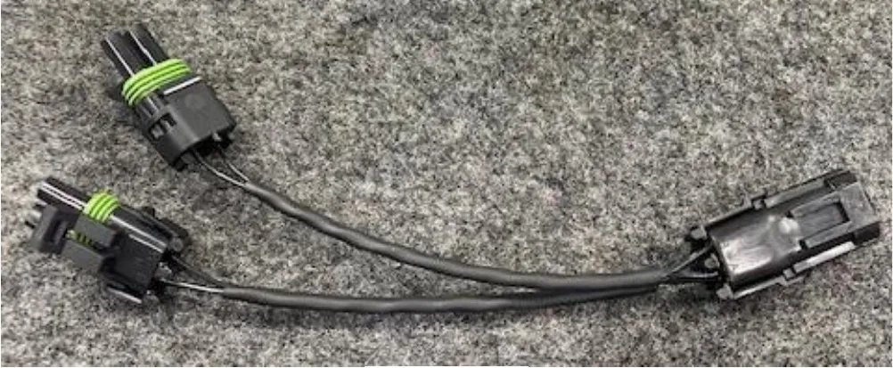
| 702RC0017 | Intercooler Fan “Y” Harness | 1 |
| 953RU0331 | Defender Turbocharger Oil Feed Line | 1 |
| 953RU0418 | M12 X 1.5mm Banjo Bolt with 2 Copper Washers | 1 |
| 702RC0023 | Defender Intercooler-Fuel Pump Harness | 1 |
| 953RU0412 | M10 X 1.0mm Banjo Bolt with 2 Copper Washer | 1 |
| 953RU0127 | 22.0mm Pinch Clamp | 1 |
| 953RU0023 | Zip Tie | 6 |
| 953RC0067 | 5/8 Black Fire Sleeve | 36 |
| 702RC0014 | Universal Intercooler Fan Wire Harness | 1 |
Procedure
Installation
- Step 1
Remove the bed for this installation. With a 13mm socket remove all (4) nuts. Unplug the electrical connector for the taillights or any other accessories you may have installed. Disconnect the box shock. Remove bed.
- Step 2
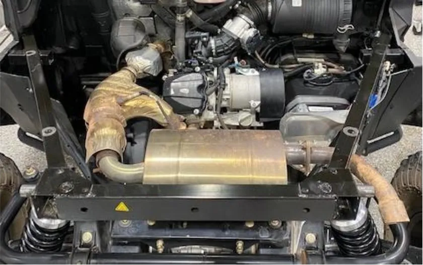
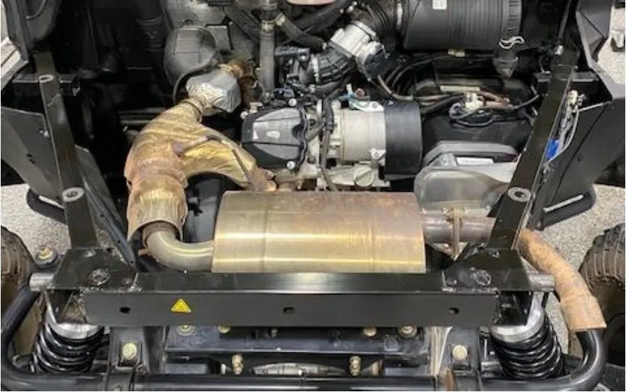
Remove the exhaust muffler using a 13mm wrench. (2) bolts and (1) bushing. Loosen the exhaust clamp fasten to the down pipe. You may need to remove some heat shield.
- Step 3
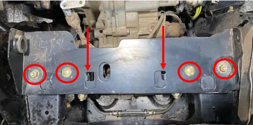
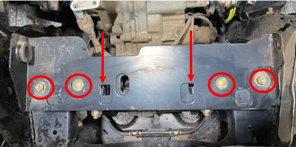
Remove the exhaust muffler bracket using a 13mm socket. There are (2) carriage bolts and (2) normal bolts. When removing from the vehicle you need to twist (2) tabs to fully remove the bracket.
- Step 4
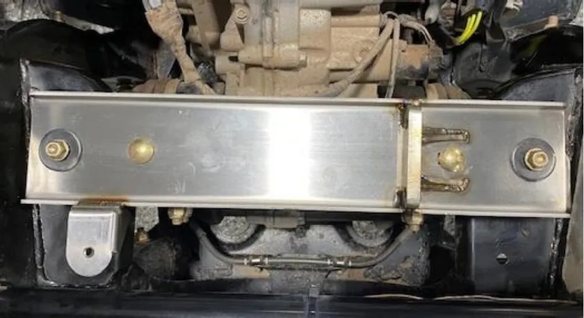
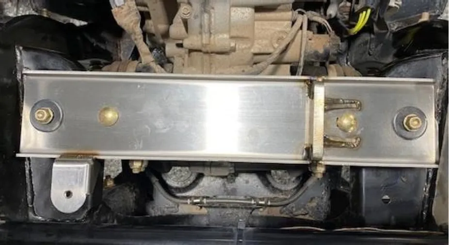
Install the new supplied turbocharger/muffler bracket in the OEM placement. Reuse OEM hardware but don’t tighten down. Keep plate loose for now.
- Step 5
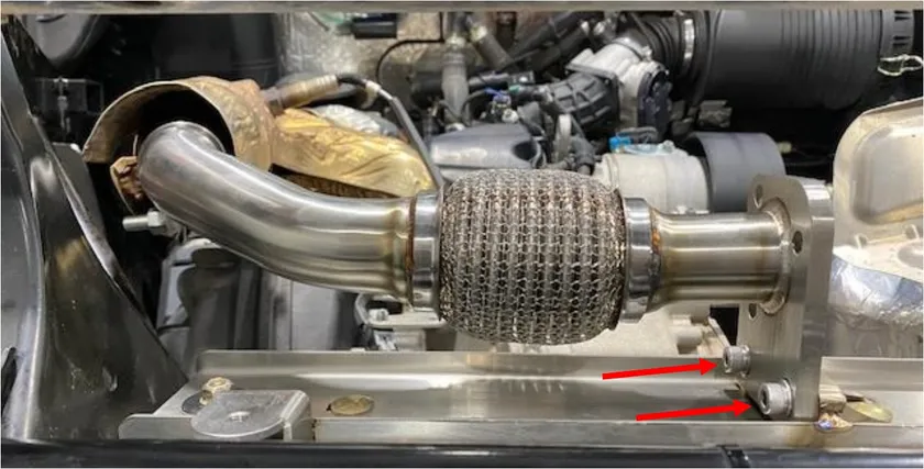
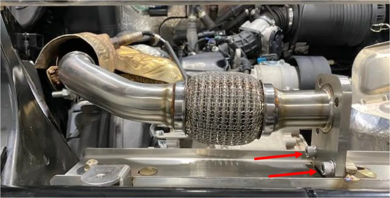
Install the supplied exhaust clamp onto the exhaust inlet pipe. Install the exhaust pipe onto the vehicle. Applied anti-seize to the threads of (2) M8x30 screws. Install the M8x30 screws with M8 washers to the muffler/turbocharger bracket. Fasten down the exhaust bracket after using a 13mm socket. Fasten down the exhaust clamp with a 15mm socket. Fasten down any heat shields you may have loosened.
- Step 6
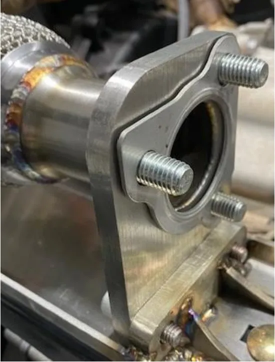
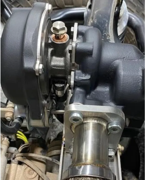
Install the turbocharger exhaust gasket and (3) M10x30mm low profile Allen screws. Apply anti-seize on the thread of the bolts. Install the turbocharger and fasten bolts down to 38 ft/lb. A 7mm ball end nose Allen wrench works best.
- Step 7
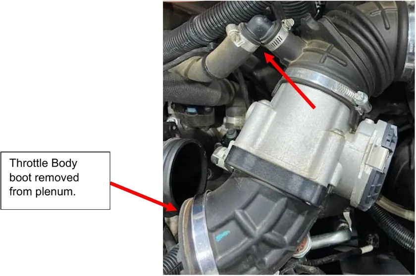
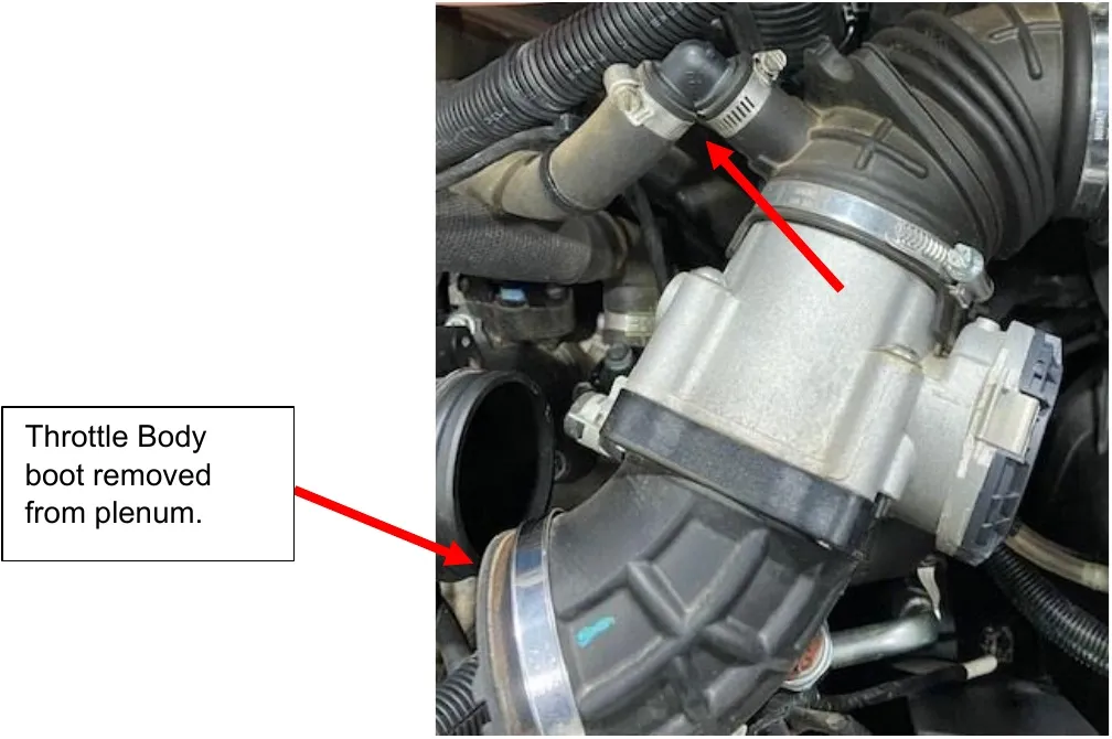
Remove the boot between the throttle body and plenum. Loosen hose clamp. Remove the crankcase breather tube from the throttle body rubber port.
- Step 8
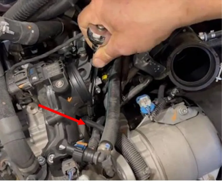
Underneath the plenum, you will locate a M5 Allen on top of the engine block. Remove the Allen with a M5 socket. Be careful it is a tight space. A swivel may be needed.
- Step 9
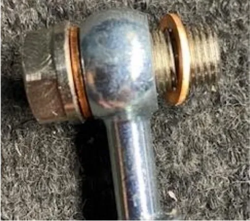
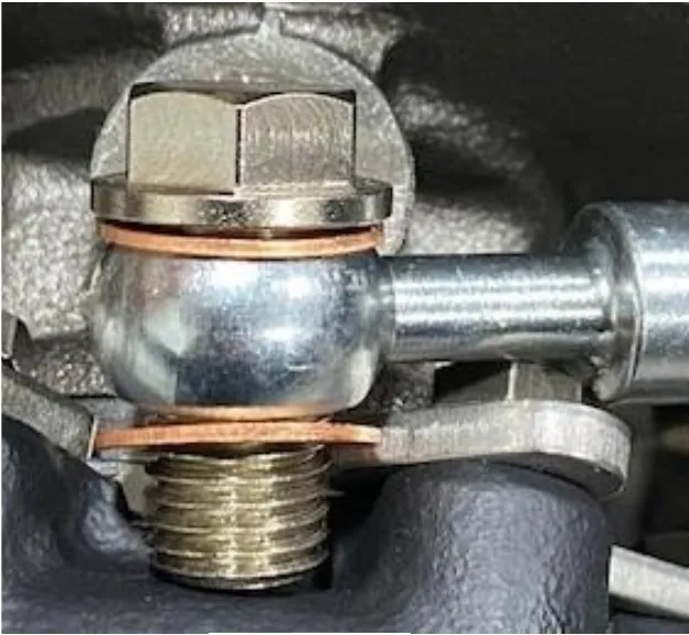
Install the oil return line where the M5 Allen was removed from. Install all components in order like shown below. From left to right; copper washer, oil feed line banjo, copper washer. Route the oil line towards the passenger side of the vehicle and back towards the turbocharger.
- Step 10
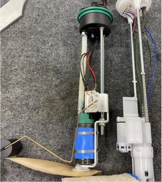
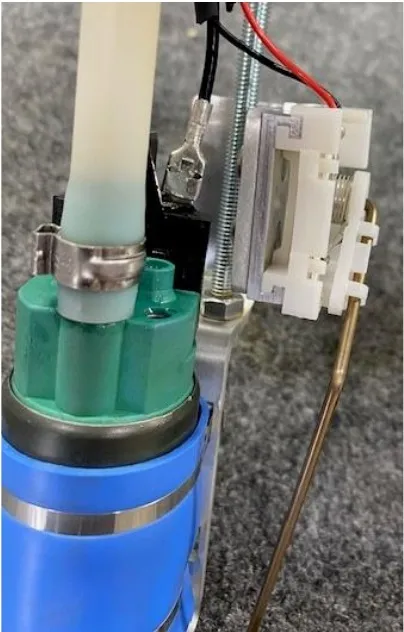
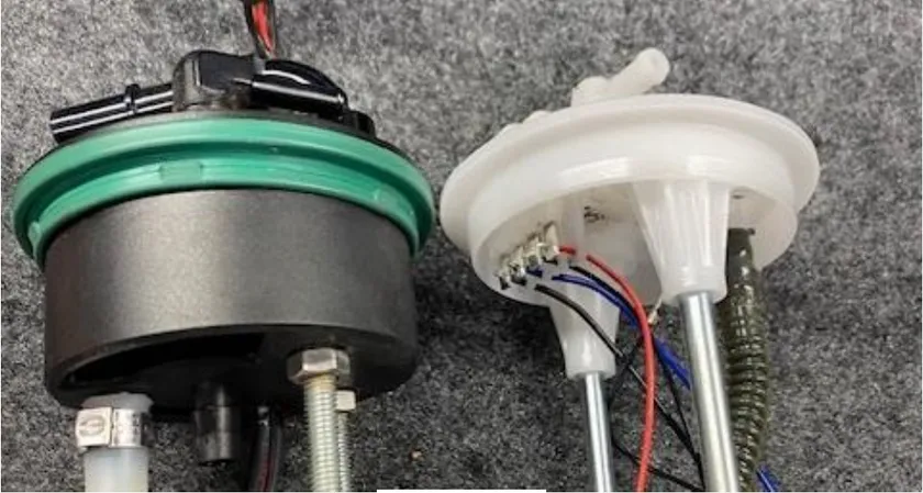
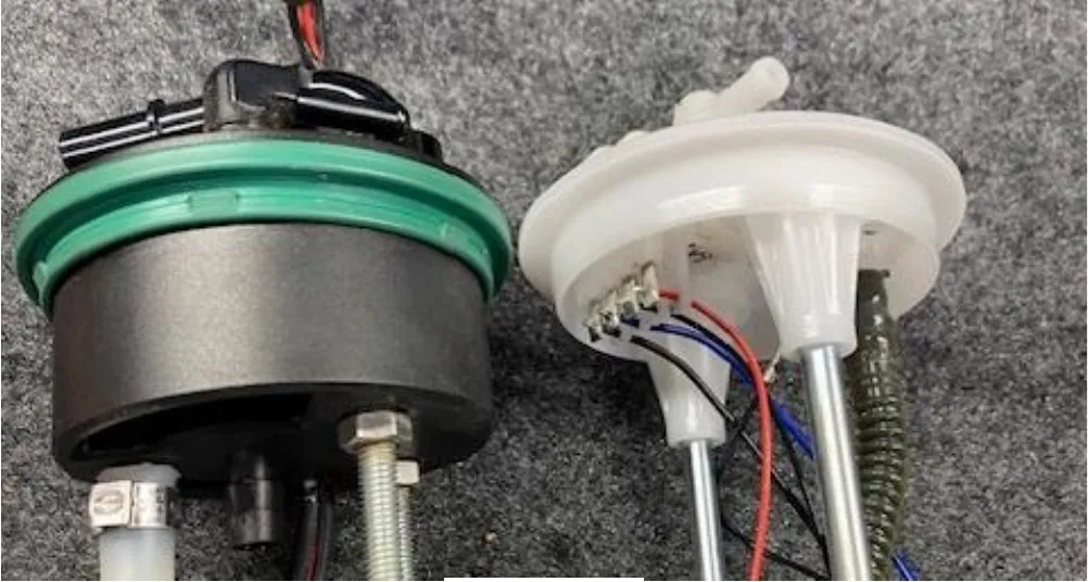
Remove the fuel put nut and disconnect the fuel hoses. Remove the fuel pump assembly and place on a clean work bench. Remove the fuel float and cut the wires, transfer the float over to the new fuel pump assembly. Soder the float wires to the new fuel pump. Remove the OEM green seal and install onto the new billet hat.
- Step 11
Install the supplied quick connect fuel connector onto the OEM fuel hose, use supplied pinch clamp to tighten down.
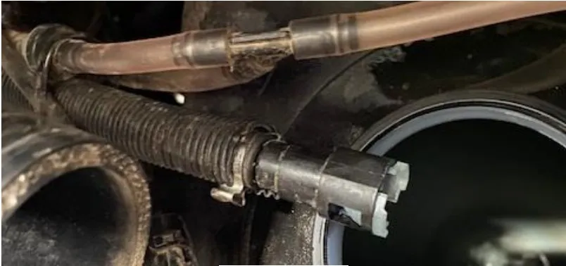
- Step 12
Turn all the fittings inward so the fuel nut will fit over the billet hat.
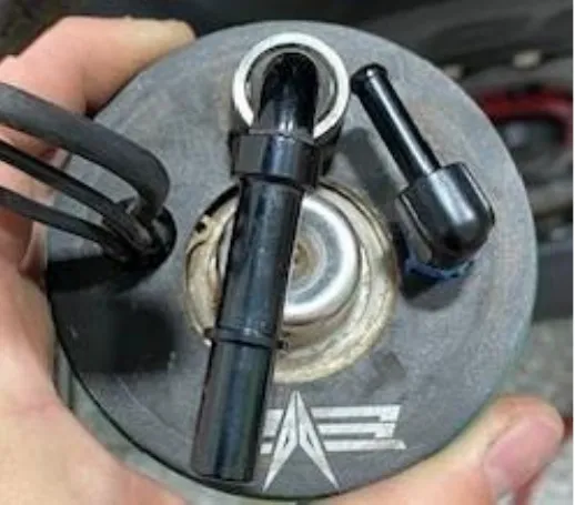
- Step 13
Install the fuel pump assembly into the fuel tank. The sock and float should face backwards.
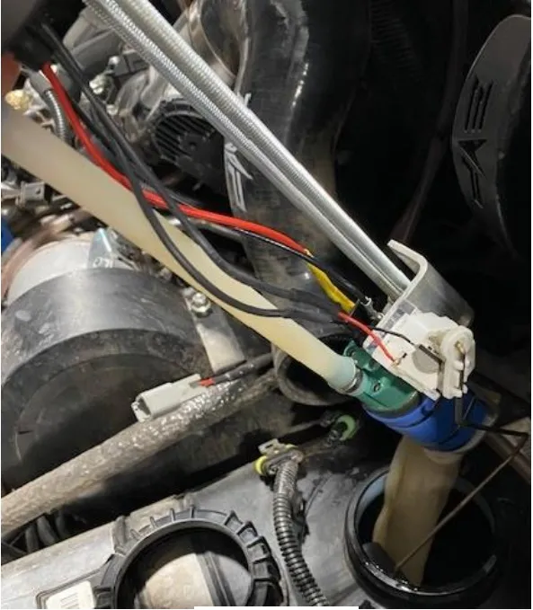
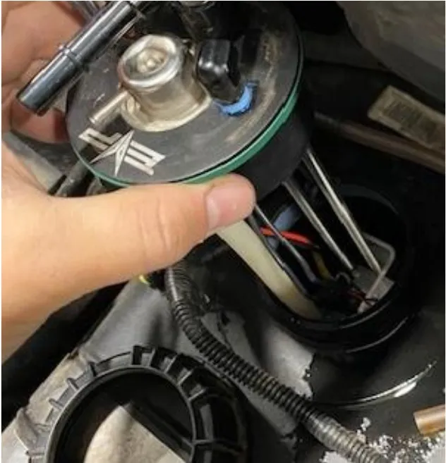
- Step 14
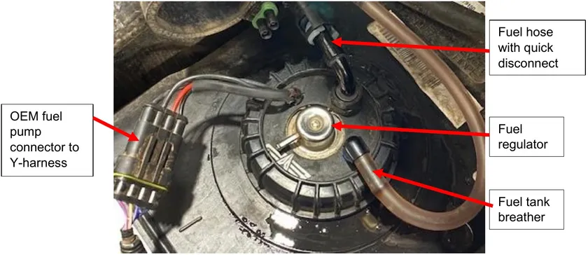
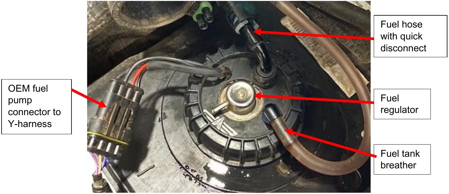
Tighten the fuel pump nut and install the hoses as shown below.
- Step 15
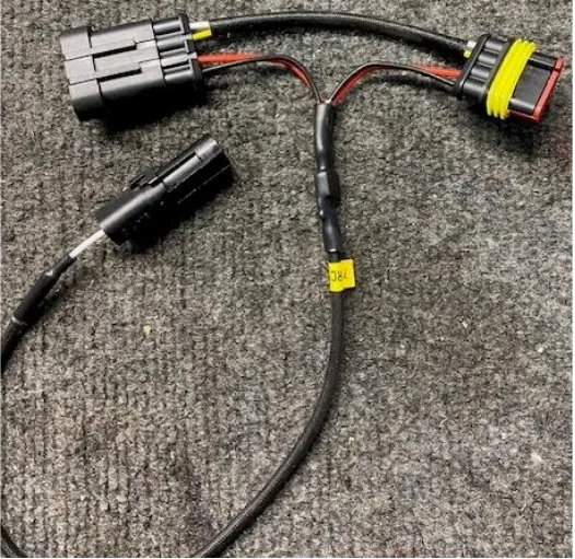
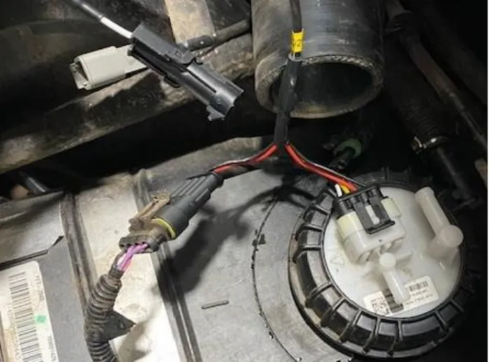
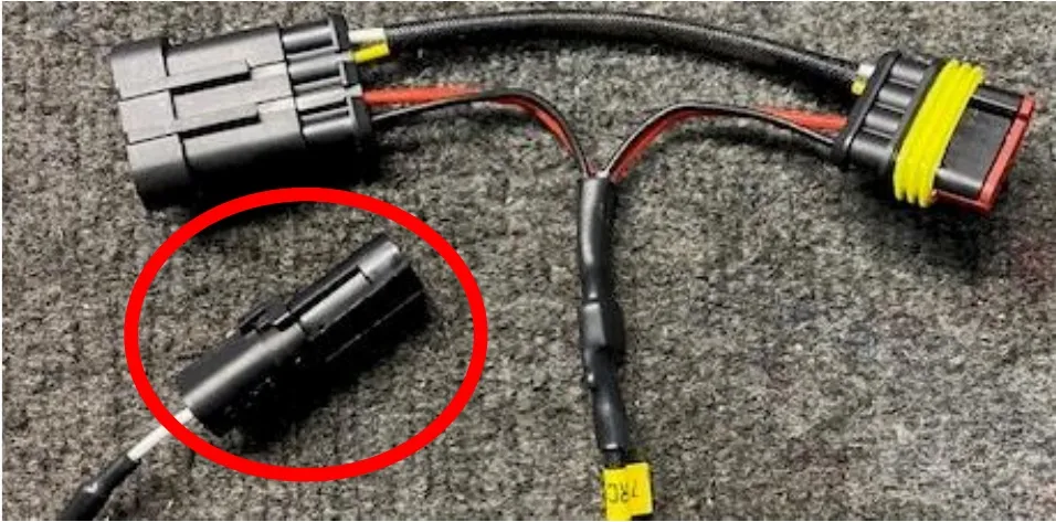
Install the fuel pump “Y-harness” onto the fuel pump. The male end will connect to the fuel pump hat and the female connector will plug into the OEM harness. The one pin connector will be used later. Keep free for now.
- Step 16
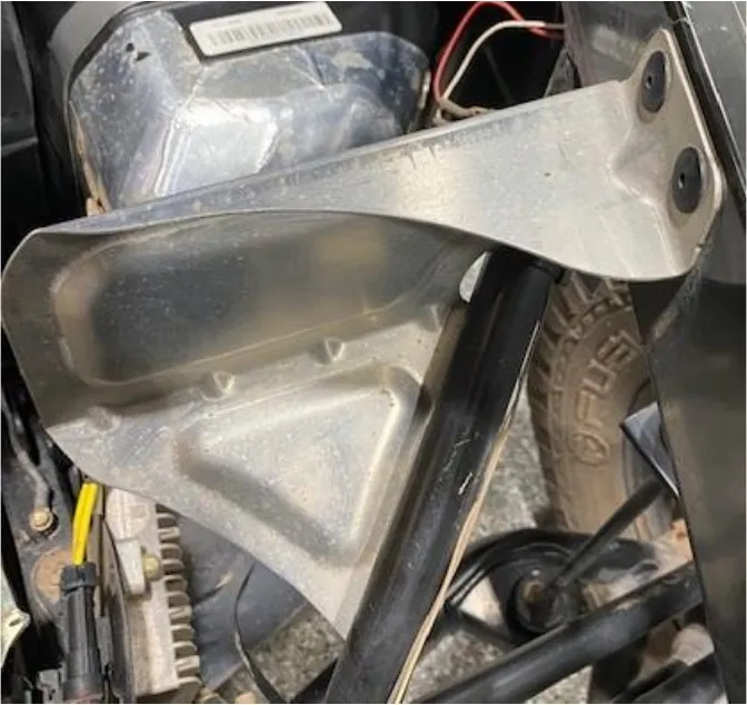
With a 3/16” drill bit, drill out (5) rivets holding the heat shield onto the frame.
- Step 17
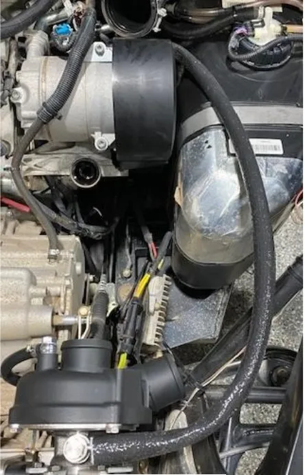
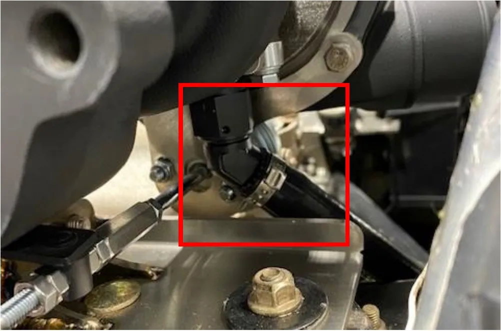
Install 36” of fire sleeve onto the oil feed line. Install the oil feed line to the turbocharger with supplied banjo bolt and sealing washers on each side of the oil line.
- Step 18
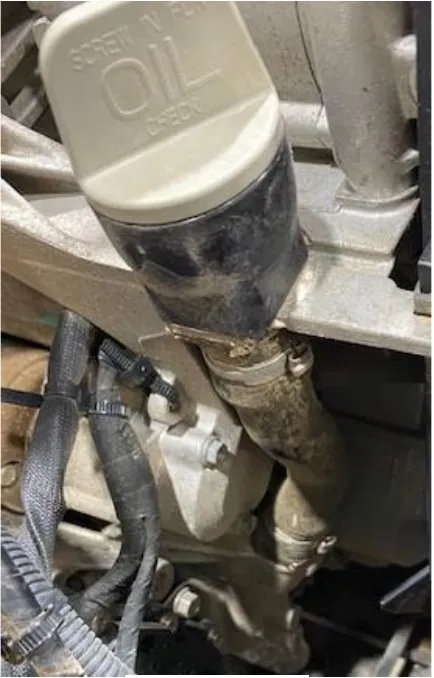
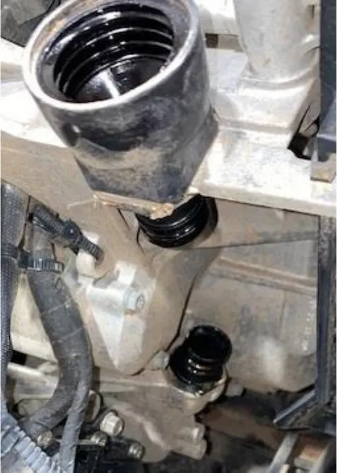
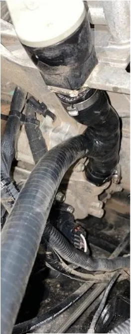
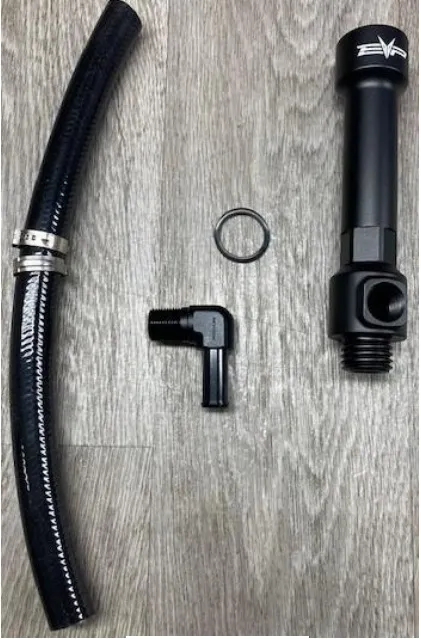
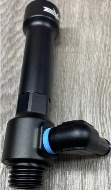
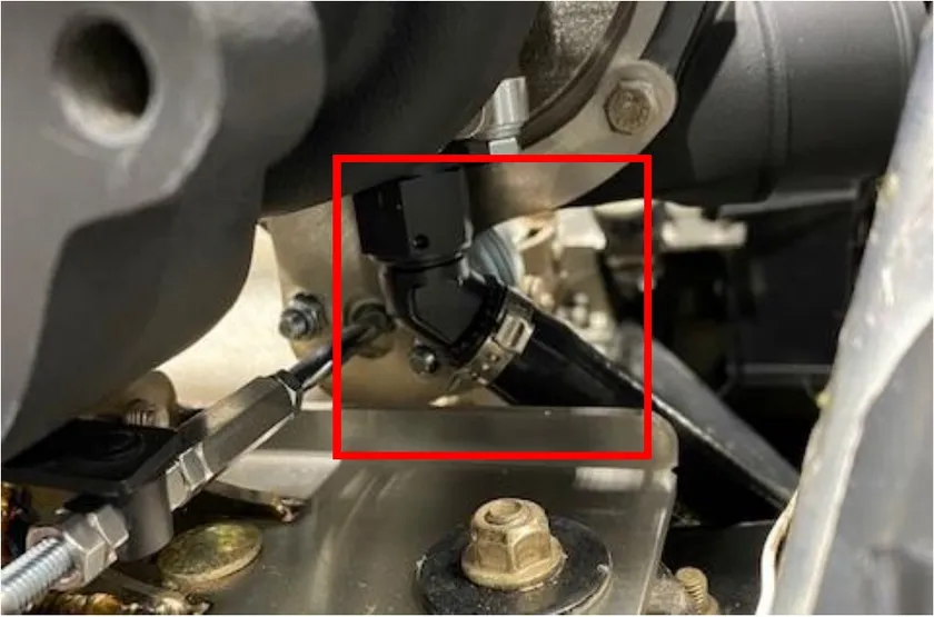
Removing the oil dip stick housing will be different for AC and NON AC models. For AC Models remove the dip stick from the rubber housing, remove both pinch clamps on the OEM rubber housing and remove from the vehicle. On a NON AC Model, remove the dip stick from the plastic housing and remove the entire plastic housing from the engine block. It will be threaded into the block.
Note
For AC Models see below.
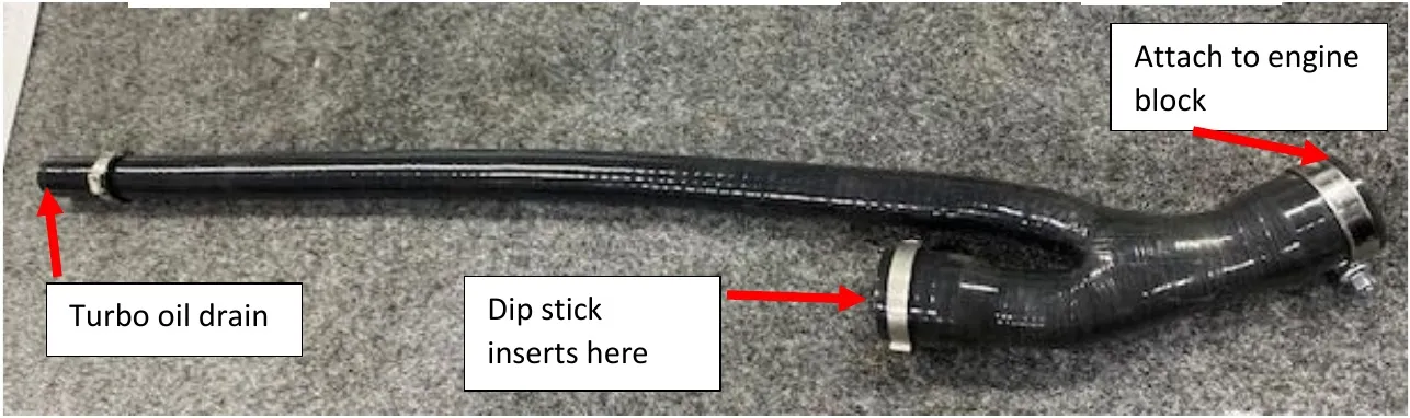
Note
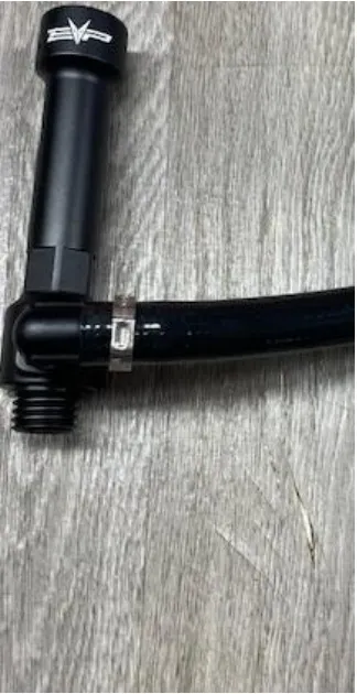
For NON AC models see below. Install the O-ring to the lower threads. Apply Teflon tape to the 90-degree fitting.
- Step 19
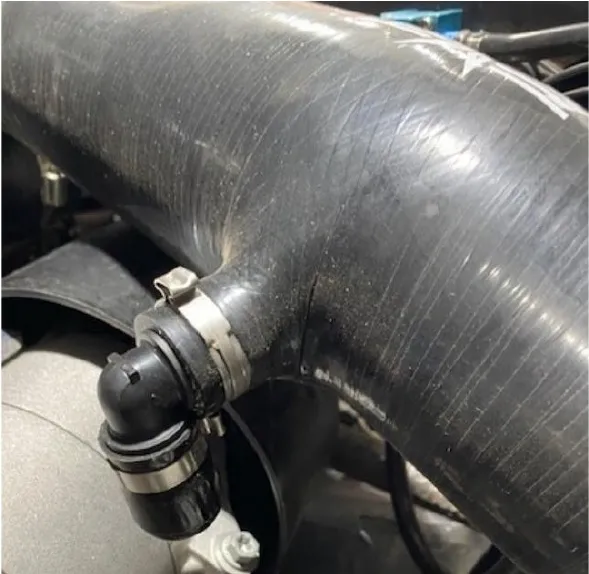
For both AC and NON AC models, run the 1/2" high temperature silicone tube from the dipstick to turbocharger oil drain. Use a pinch clamp to secure.
- Step 20
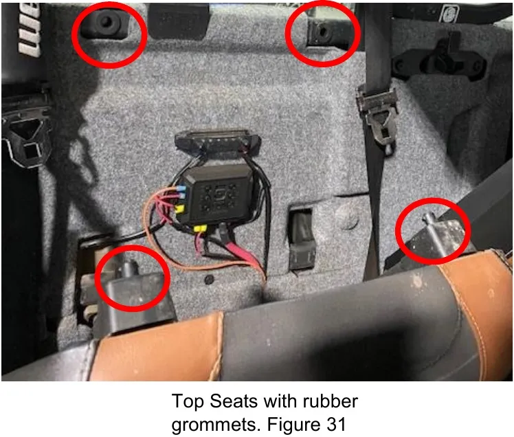
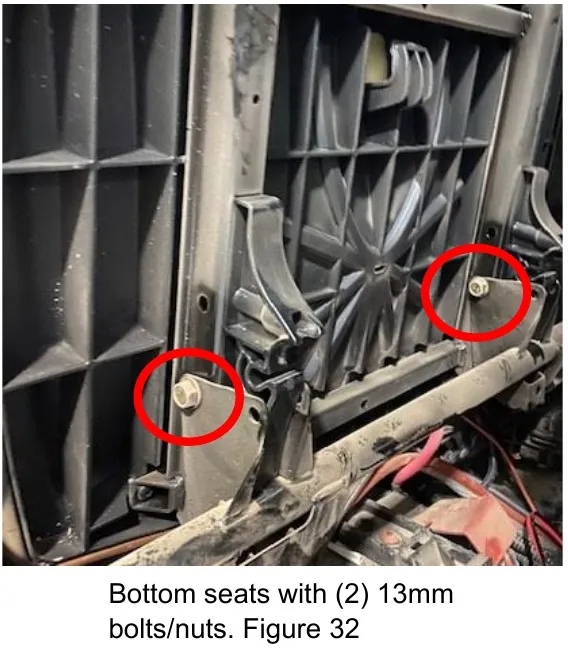
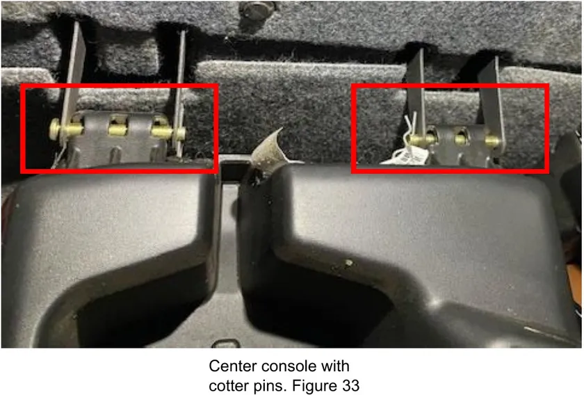
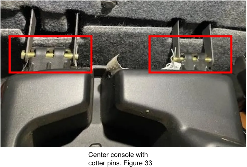
Remove the interior and seats if a single cab. Remove the rear interior sound damping and seats if a crew cab. The top of the seat pop off from rubber grommets. The lower seats remove with (2) 13mm nuts and bolts per seat. The center console has (2) cotter pins.
- Step 21
Remove all the sound damping material. There are two layers. Remove using a push dart tool and T-25 socket. You may need to remove the rear glass supports to fully remove the damping material.
- Step 22
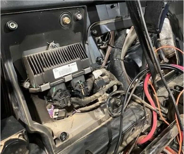
After the damping material is removed you will remove the rear access panel using a T-30 socket. There will be (8) screws total. This will allow access to the engine bay and ECU.
- Step 23
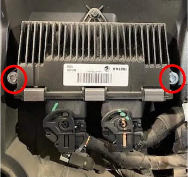
Remove the ECU from the firewall. Use a 8mm socket. You will need to access a bolt behind the ECU. Keep the ECU plugs connected.
- Step 24
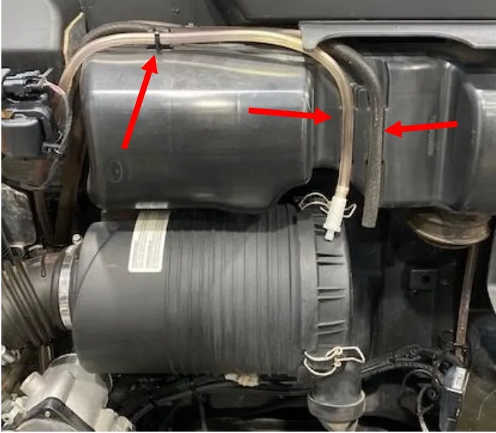
If your vehicle is equipped with a snorkel kit, remove (3) hoses connected to the snorkel box. Lay them to the side.
- Step 25
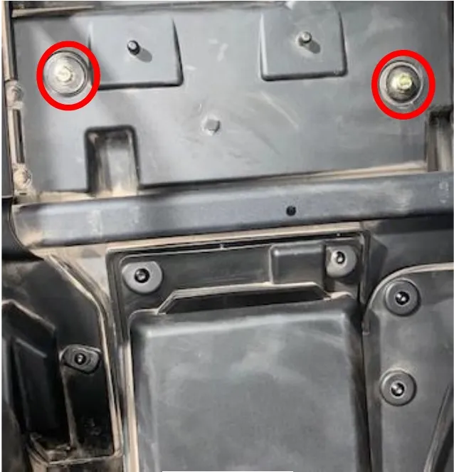
On the inside of the cab, above the ECU, remove the (2) bolts using a 13mm socket. This will remove the snorkel box (if your vehicle is equipped with it.)
- Step 26
On the inside of the cab, behind the ECU you previously removed, remove (2) bolts using a 13mm socket. This will remove the airbox.
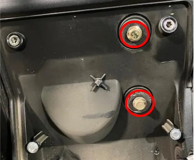
- Step 27
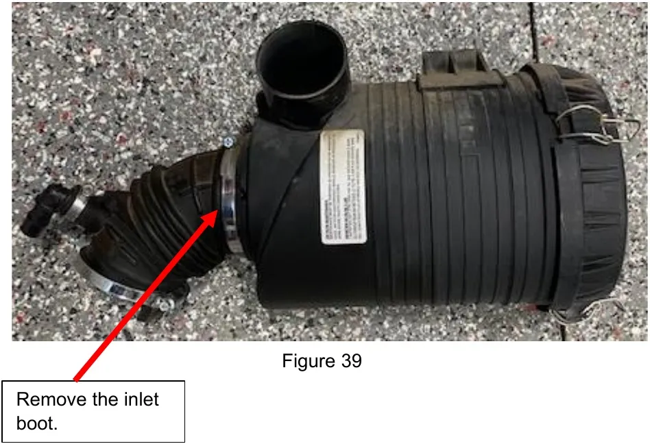
With the airbox removed, remove the rubber boot attached to the inlet.
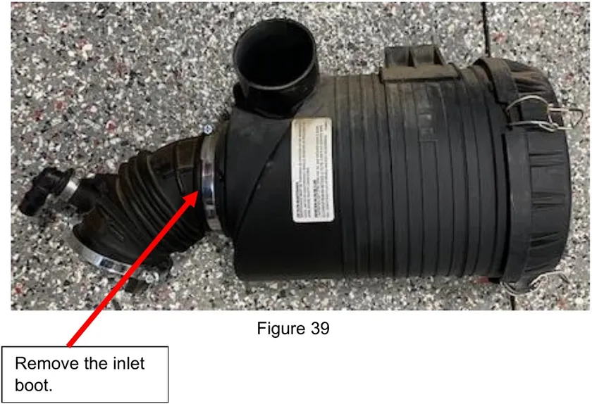
Remove the inlet boot. - Step 28
(OPTIONAL HFI Instructions below) On the inlet of the airbox you will find a tab. Grind or sand this tab off.
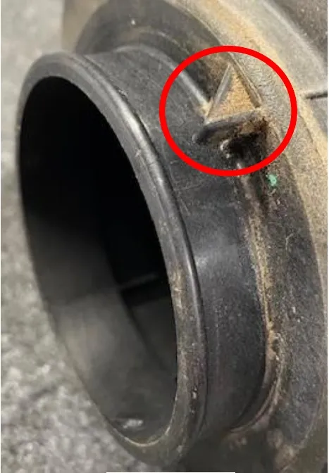
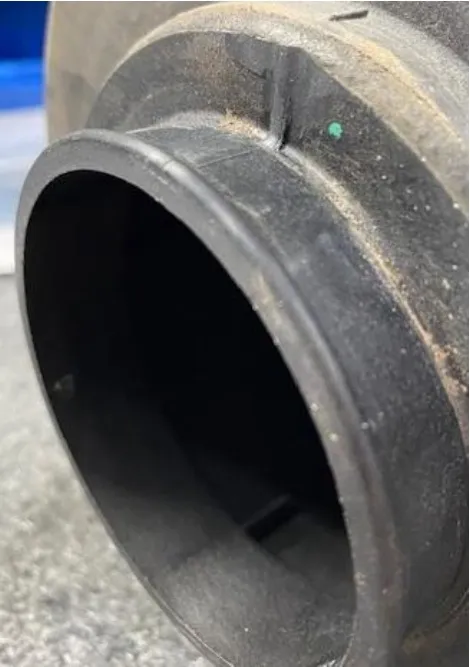
- Step 29
Remove the old air filter and blow out the inside of the airbox. Install the supplied air filter and pre filter. Resecure the airbox lid.
- Step 30
Open the airbox relocation kit that was supplied. You will reuse (2) OEM airbox bolts and washers.
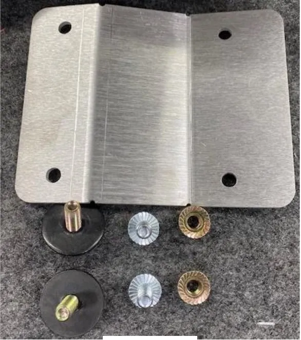
- Step 31
Install the airbox relocation plate onto the airbox. Use (2) M8x20mm screws.
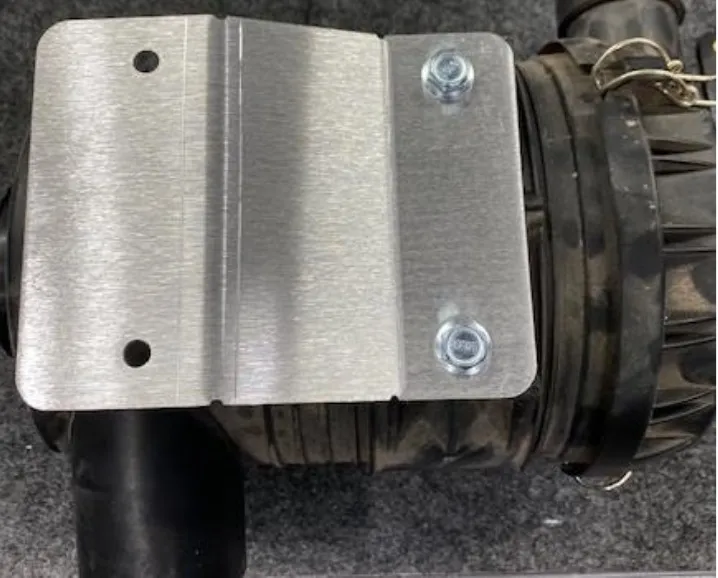
- Step 32
Install the airbox with relocation bracket into the vehicle. Reuse (2) OEM bolts and washers from the inside of the vehicle into the engine bay. Use (2) supplied M8 nuts to fasten down the bracket. Make sure the steel sleeves are still in the firewall.
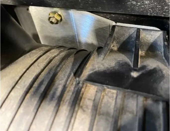
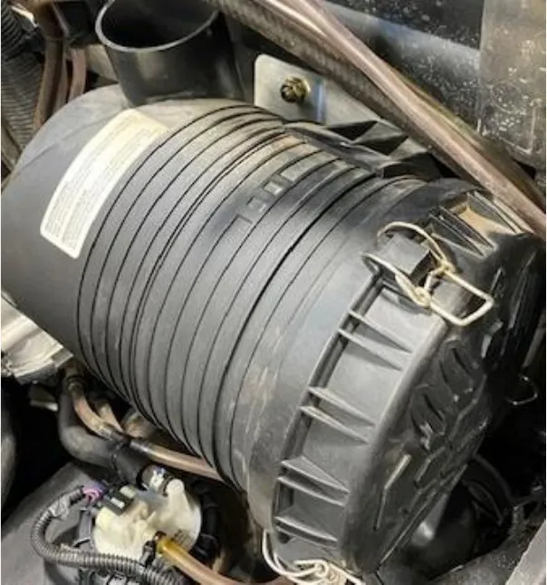
- Step 33
(OPTIONAL) High Flow Intake. Install the high flow intake bracket and hardware where the OEM airbox was removed from.

- Step 34
Hold the shim into the pocket of the firewall. Mark both holes with a silver sharpie and drill with a 7/16” drill bit.
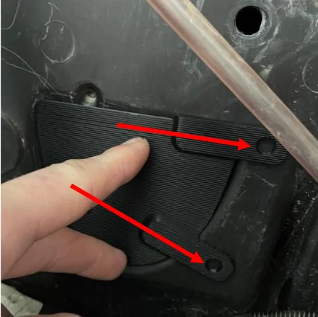 Caution
Make sure your ECU is removed first!
- Step 35
Mount the high flow bracket to the shim using a M8x16mm and M8 locknut. Tighten down straight.
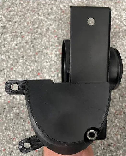
- Step 36
Mount the bracket back to the firewall and with a silver sharpie mark the top hole on the bracket. Drill with a 7/16” drill bit.
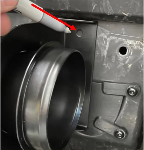
- Step 37
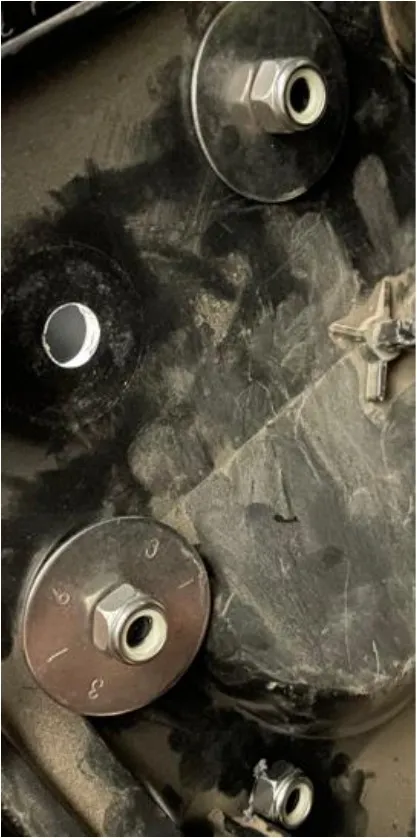
Mount the bracket using the remaining M8x20mm screws, locknuts and oversized washers. No oversized washer on the lower screw. See below.
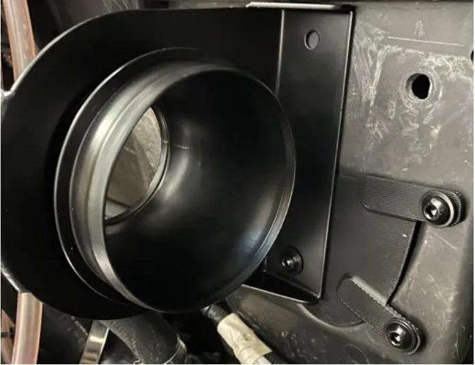
- Step 38
Reinstall the ECU to the firewall. Use a 8mm socket, do NOT over tighten the plastic screws.
- Step 39
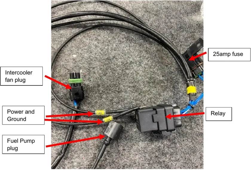
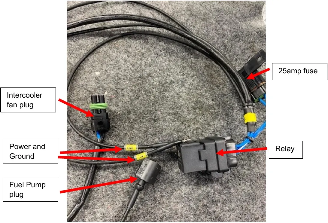
Install the supplied intercooler fan harness. Power and ground will be connected directly to the battery. The relay can we mounted to a stud or zip tied. The other two ends will go through the engine access panel. One lead is for the fuel pump Y-harness and the other is for the intercooler fans.
- Step 40
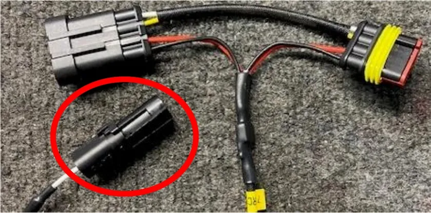
Route the fuel pump plug away from heat source and connect to the fuel pump “Y-harness previously installed in step 15. Zip tie any excess wire.
- Step 41
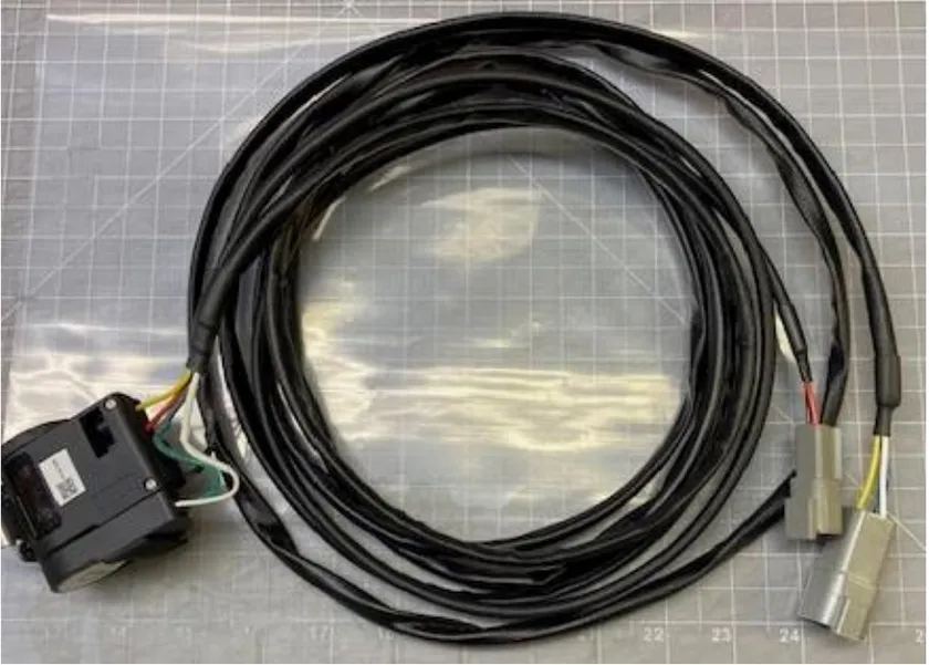
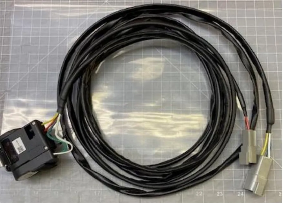
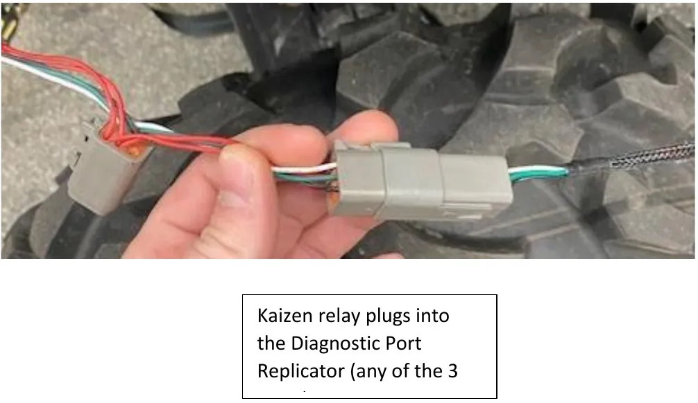
Install the Kaizen relay module down by the battery and run the larger grey connector underneath the floor up to the front dash. This will plug into the diagnostic port replicator. Run the small grey connector through the fire wall and towards the intercooler. This will connect to the boost control module.
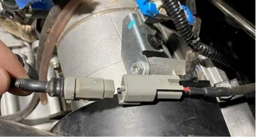
- Step 42
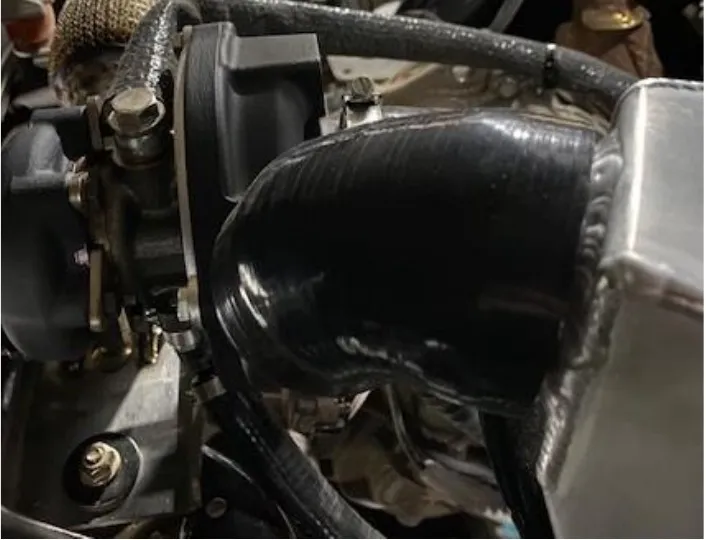
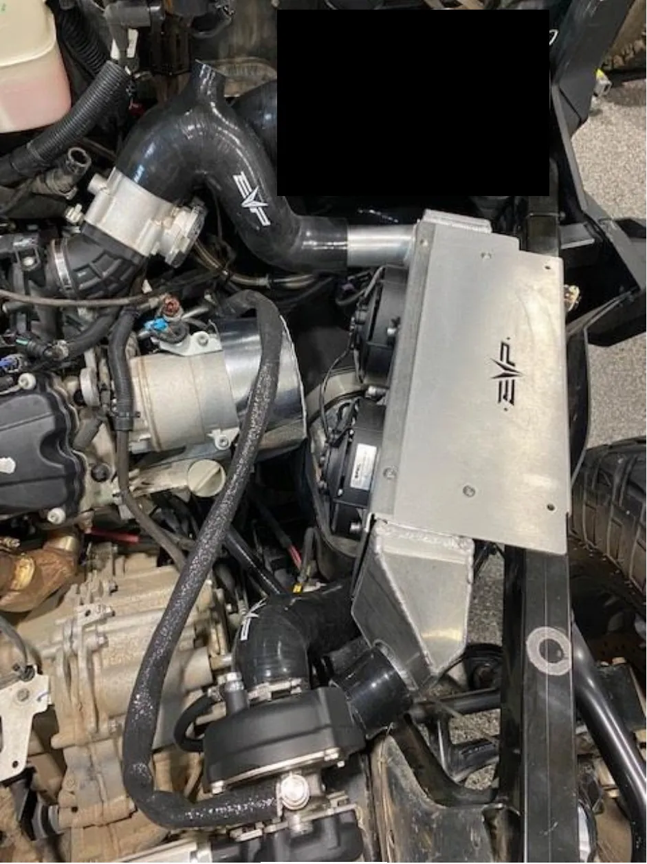
Plug in the EVP diagnostic port replicator into the OEM diagnostic port found under the front hood. 2020-2021 Defenders will use the diagnostic port replicator with a black stripe over the part number. 2022+ Defenders will use the diagnostic port replicator with no stripe over the part number. Route this into the cab. Install the intercooler assembly into the vehicle. Install the throttle body to intercooler (shaped like a “7” with a BOV port) and turbocharger to intercooler (small 4” long 45-degree) silicone pieces, loosely, no clamps required yet. Make sure the throttle body is clamped down to the plenum. Change out the OEM clamp with supplied 50-70mm. Check fitment, make sure the intercooler is centered with no excess pressures on the charge tubes.
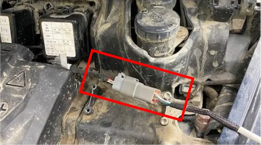
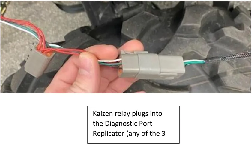
Kaizen relay plugs into the Diagnostic Port Replicator (any of the 3 ports) 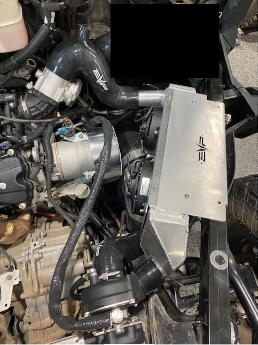
- Step 43
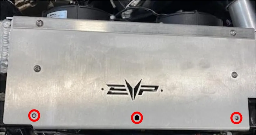
With a silver sharpie, dot the center of all (3) intercooler mounting locations. Remove the intercooler and silicone once complete.
- Step 44
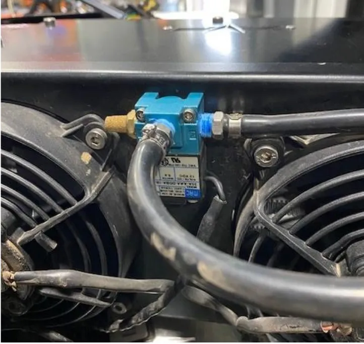
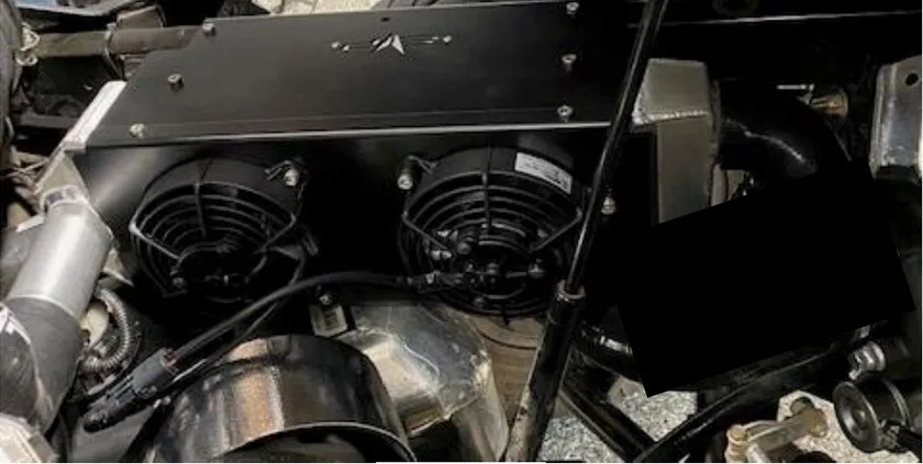
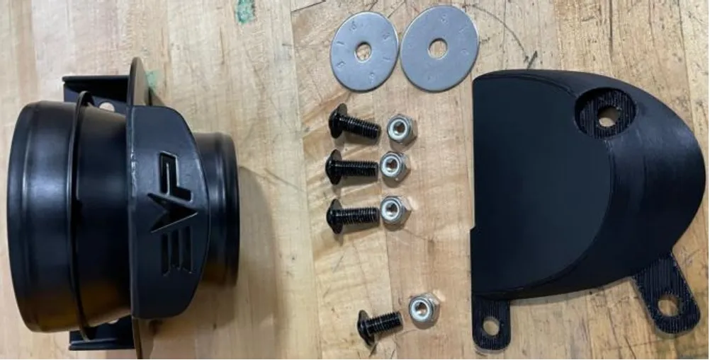
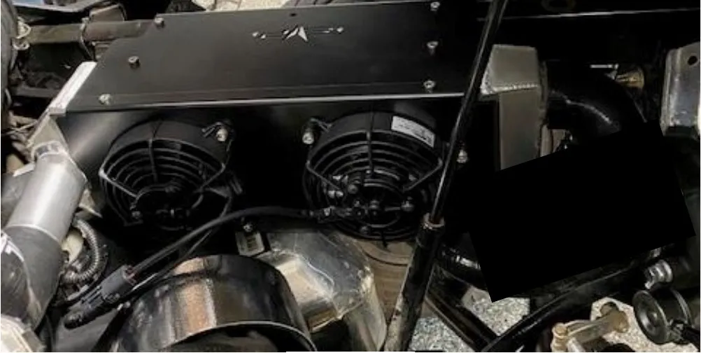
Remove the fan shroud and mount the boost control module between the fans. Use a small drill bit and mount with supplied hardware.
- Step 45
Drill (3) pilot holes over your sharpie marks. Next drill with a 25/64” drill bit all (3) holes. Do NOT auger the holes out.
- Step 46
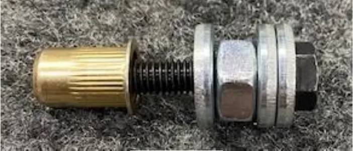
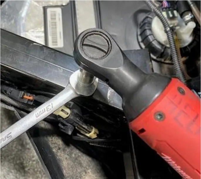
Insert the supplied nutserts and install with a nutsert tool. If you do not have a nutsert tool, grab the supplied (1) M6x40mm bolt, (3) oversized M6 washers and (1) M8 nut. Install the hardware together like shown below.
- Step 47
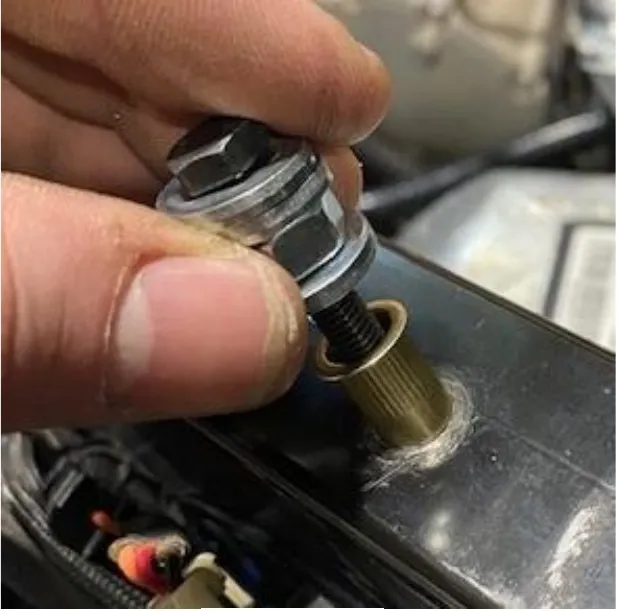
Install the nutsert and hardware into the hole previously drilled. Use a 12mm open end wrench to hold the M8 nut and a 10mm socket paired with a lite duty ratch wrench. Press down on the open end wrench and tighten the M6x40mm bolt with the ratch wrench. Apply decent pressure but don’t over tighten. Once complete, remove the M6x40mm bolt and hardware. Check to make sure the nutsert was compressed completely. Do the following (2) nutserts the same way.
- Step 48
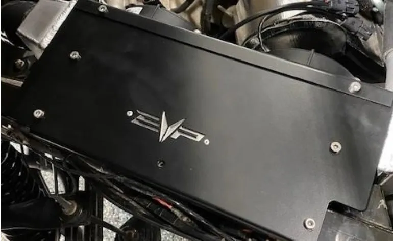
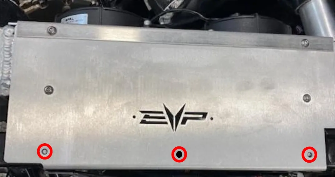
Install the backing plate onto the “EVP” cut out on the intercooler shroud. Use supplied 1/8” rivets.
- Step 49
Reinstall the intercooler and silicone. Fasten down the intercooler with (3) M6 low profile button head screws. Fasten down the turbocharger to intercooler hose with (2) 40-60mm clamps. Fasten down the throttle body to intercooler hose with (1) 50-70mm & (1) 60-80mm clamps.
- Step 50
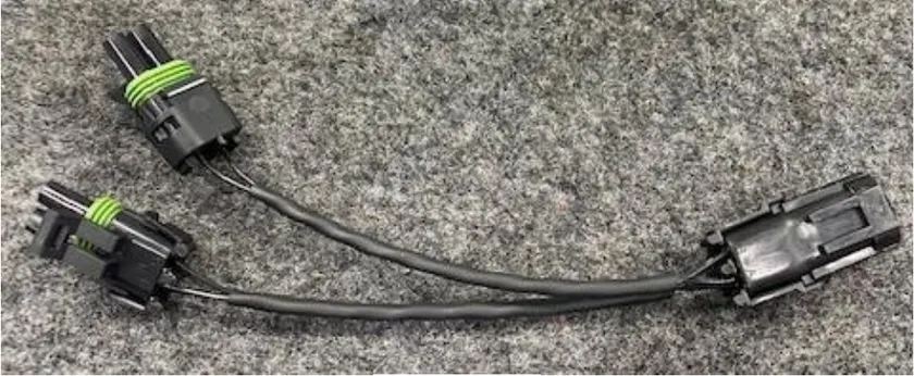
Install the intercooler “Y” harness to the intercooler fans. Connect the other end of “Y” harness to the relay harness we fed through the firewall.
- Step 51
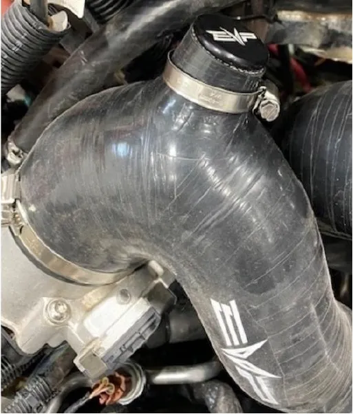
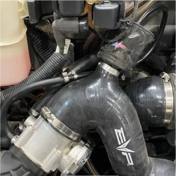
If you are NOT installing a BOV install the supplied BOV plug and tighten down with a 25-40mm clamp. If you are installing a BOV, install the prefilter onto the BOV and install into the charge tube. Fasten down with a 25-40mm clamp. Locate the throttle body and remove the rubber plug. Install the 6mm vacuum line onto the throttle body port. Install 3mm vacuum line onto the BOV. Connect the vacuum lines with supplied coupler. Use pinch clamps to fasten down all vacuum line.
- Step 52
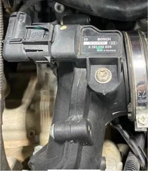
Locate the MAP sensor on top of the plenum. Remove the connector and screw using a T-30 socket. Install the supplied MAP sensor, apply dielectric grease on the O-ring. Reconnect the electrical connector and screw.
- Step 53
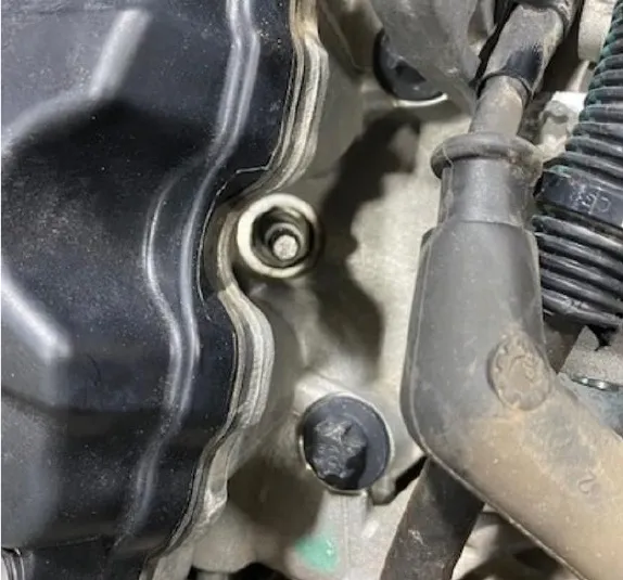
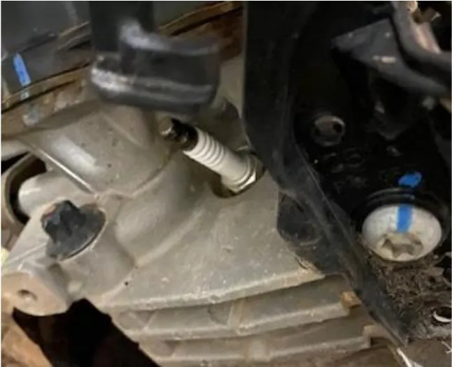
Locate both spark plugs, remove the spark plug boots and spark plugs using a 5/8” socket. Install supplied EVP spark plugs. You can apply anti seize on the threads.
- Step 54
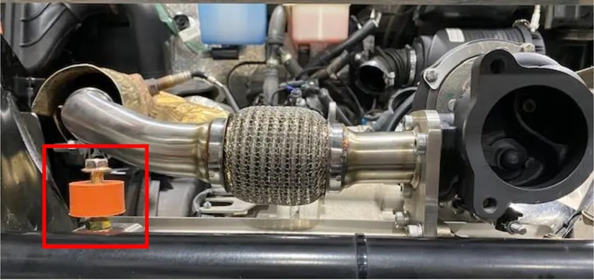
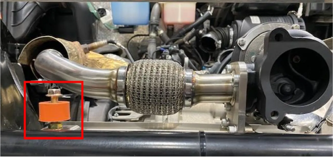
Install supplied M8 nut to the rubber isolator, install the isolator onto the muffler support bracket. Install M8x25mm screw into the top of the isolator.
- Step 55
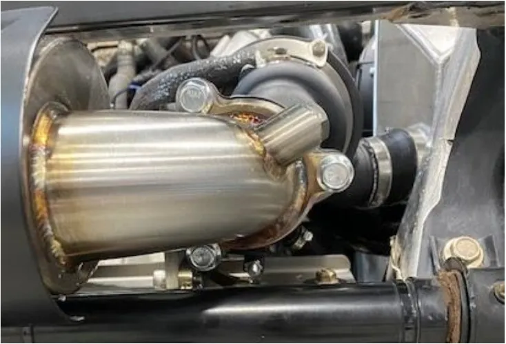
Install the exhaust gasket onto the muffler with (3) M10x20mm screws. Install the muffler to the turbocharger and rubber isolator. Torque bolts to 38 ft-lb. Tighten the rubber isolator screw.
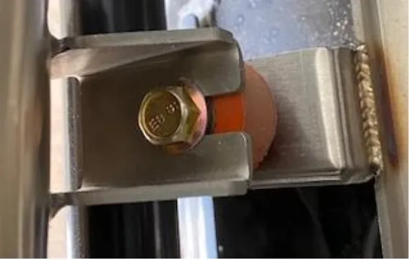
- Step 56
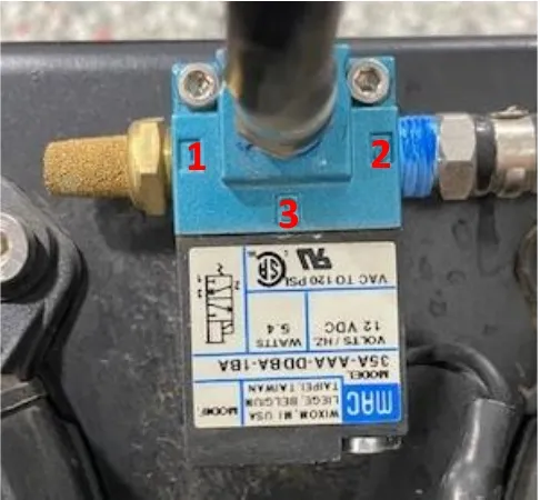
Connect the boost control solenoid to the turbocharger. Port 1 is the muffler. Port 2 will connect to the wastegate. Port 3 will connect to the turbocharger.

- Step 57
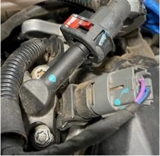
Locate the injectors, remove the electrical connector and remove the (2) screws with an 8mm socket.
- Step 58
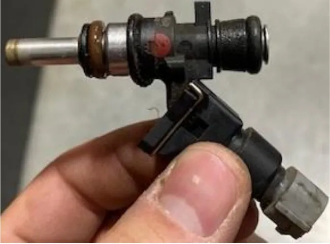
Remove the stock injector and install the supplied EVP injector. Use dielectric grease on the O-rings.
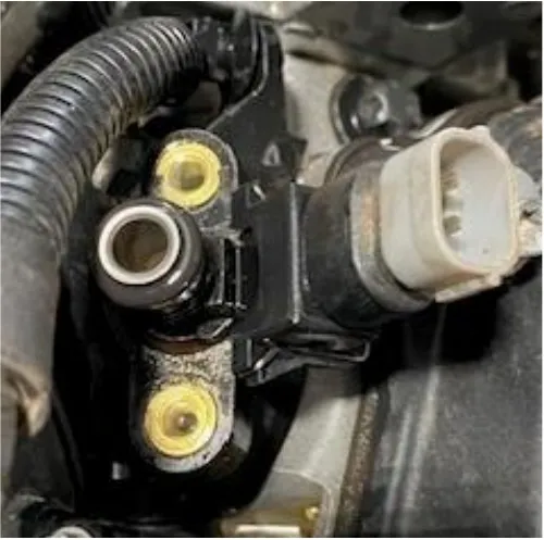
- Step 59
Install the high flow air filter onto the bracket.
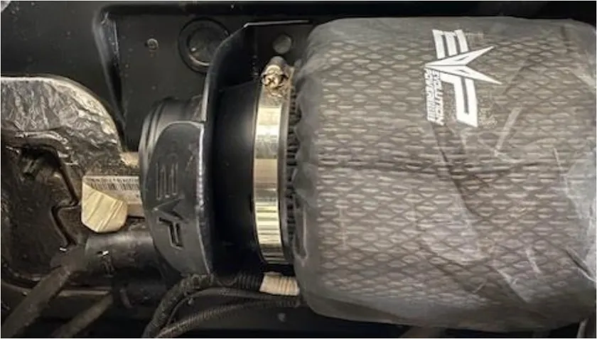
- Step 60
Install the high flow intake tube onto the turbocharger and air filter bracket. Fasten down with supplied clamps.
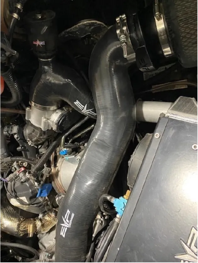
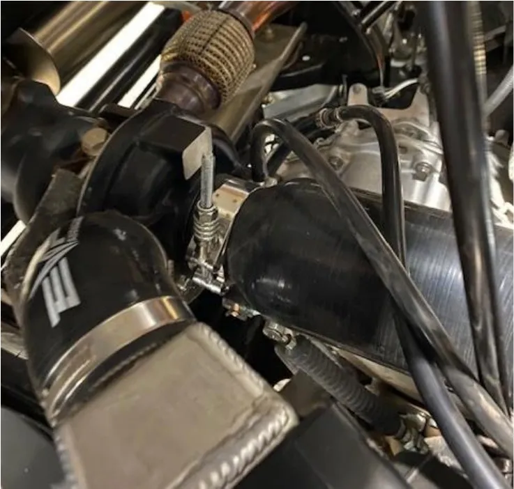
- Step 61
If you’re running a catch can, cap this port off. If you’re not running a catch can, connect your 5/8” supplied hose from the crank case to this port.
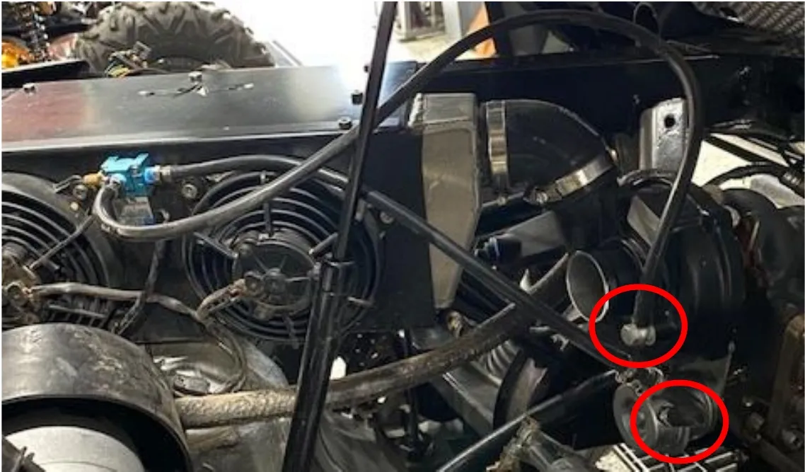
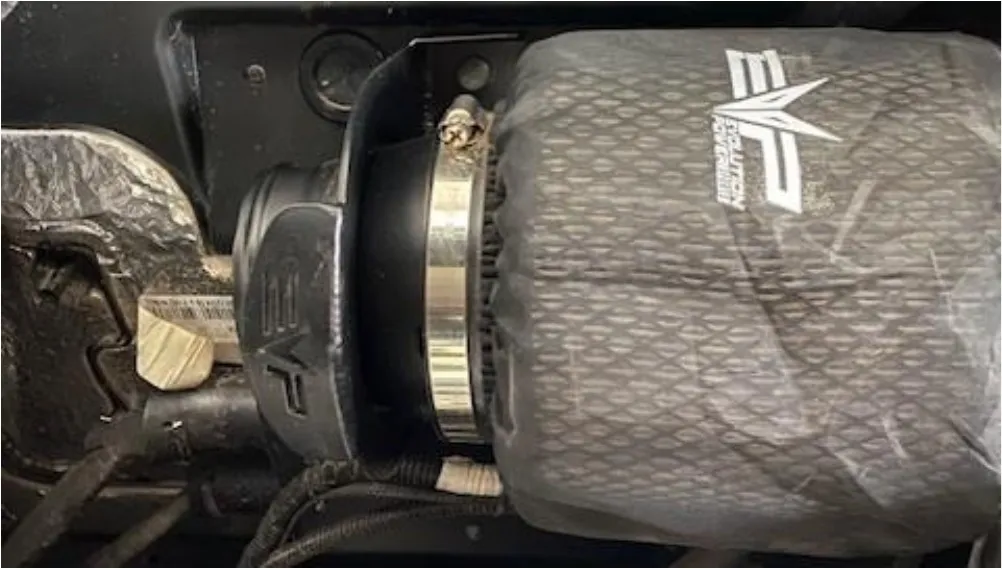
Procedure
Defender Oil Change
- Step 1
Remove the oil dip stick.
- Step 2
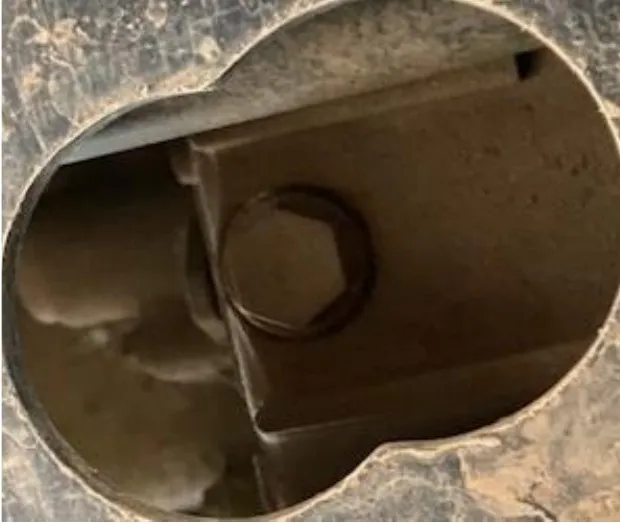
Underneath the car you will locate the oil drain plug. Use a 17mm socket to remove the drain plug and sealing washer. Use a drain pan to catch the oil.
- Step 3
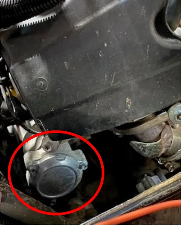
With the firewall access panel removed (from turbocharger installation) locate the oil filter. Remove (3) 8mm bolts holding the oil filter cap on. Remove the filter.
- Step 4
Install the new oil filter and O-ring on the oil filter cap. Reinstall the oil filter cap.
- Step 5
Remove the old sealing washer off the drain plug. Install supplied sealing washer and reinstall the oil drain plug.
- Step 6
With a funnel installed in the oil dip stick tube, add 2 full liters of oil.
- Step 7
Locate the diagnostic port and hook up your CodeShooter device. Follow the step by step process to flash your vehicle.
- Step 8
Once the vehicle is flashed, start the engine. Check your oil level, the vehicle will take a little over 2 liters. Now is a good time to overlook your work and check for leaks.
- Step 9
Reinstall the full interior, zip tie any loose or extra wires.
- Step 10
Reinstall the bed.
Emissions notice. This product is exempt from the emission standards and related requirements of 40 C.F.R. § 1051 as provided by 40 C.F.R. § 1051.620, and California law [e.g., vehicle code §§ 27156 and 38391]. This product is sold only for use in connection with EPA certified, purpose-built, nonroad vehicles used solely for closed course, nonroad competition/racing and not used for any recreational purpose or on public highways or right of ways maintained by and open to the public. This product is sold only in connection with machines that do not fall under state and/or federal noise or emission standards/regulations. Purchasers who/that purchase this product represent and warrant that the product is purchased only in connection with EPA-certified, emission-regulations-exempt and noise-regulations-exempt competition/racing vehicles as interpreted under applicable state and/or federal law.
Need technical support?
Submit a ticket with your vehicle and what you're seeing, and our support team will get back to you.
